
When I first learned about PLCs, I found terms like “instructions” and “logic” to be quite abstract. It wasn’t until I started working on a marquee light program—watching the indicator lights illuminate step by step according to my written program—that I suddenly understood how to use timers and shift instructions. In fact, the marquee light program is an “excellent springboard” for beginners; the logic is not complex, and the effect is intuitive. By practicing it, you can grasp the basic instructions and also find joy in programming.1. Output and Input Configuration
Beginners don’t need to worry about “having to connect physical devices” right away; there are two ways to practice:Output: You can either connect 8 indicator lights to the PLC’s Y0~Y7 outputs or simulate them directly in GX Works2 using soft components. I was initially afraid of wiring incorrectly, so I first simulated the logic and then removed the lights from an old circuit board to test with real components, which was both safe and rewarding.Control Side: For physical devices, just find two buttons to connect to X0 (Start, normally open) and X1 (Stop, normally closed). Pressing X0 will run the program, and pressing X1 will stop it; simulation is even simpler, as you can directly click X0 “Set” and X1 “Reset” on the monitoring interface without needing to screw in wires, which is suitable for quick trial and error.2. Core Logic of the Program In essence, there are three steps: use a timer to set the “light interval” (for example, change the light every 1 second), use a counter to keep track of “how many times the light has changed” (after 8 times, start over), and then use a shift instruction to pass the “light signal” from Y0 to Y7, like passing an item in a queue. The timer is the “rhythm of passing,” and the counter is the “how many rounds to reset.” Once the logic is clear, the program becomes easy to write.3. Complete Ladder Diagram Program (Step-by-Step Analysis)1. Start/Stop Control: First, set up a switch
Initially, I didn’t add this holding circuit; the lights would run when I pressed X0, but they would stop as soon as I let go. Later, I realized that M0 is the “run enable”—pressing X0 sets M0 to 1 and holds it, allowing the program to run continuously; pressing X1 resets M0, turning off all the lights, effectively adding a “master switch” to the program, which is safe and convenient.2. Timer Control (1-second interval)
Beginners often confuse “timer base”; for example, T0 is in 100ms units, so to change the light every second, you need to set K10 (10 times 100ms). I mistakenly set it to K1 at first, resulting in the lights flashing too quickly. After adjusting the K value, it worked normally—remember “base time × K value = actual time”; adjusting the speed relies on changing the K value.3. Counter Control (8 times cycle reset)

To cycle through 8 lights, the counter must reset after counting to 8. For example, when C0 counts to 8, it indicates that Y0 to Y7 have all been lit; at this point, C0 resets itself, and the next shift will start again from Y0—I initially forgot to add the reset, resulting in the lights stopping at Y7. Adding this loop allowed for the cycle to be completed.4. Shift Instruction (Sequentially Lighting Up the Indicator Lights)

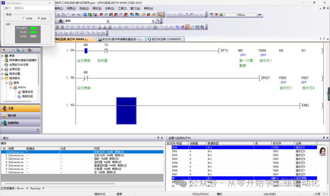
SFTL: Left shift instruction; M2: shift data source (initially “1”); Y0: shift target starting address; K8: total of 8 target bits (Y0~Y7);K1: shift 1 bit each time;It is important to note: shifting requires an “initial signal”; during the first T0 action, M2’s “1” shifts to Y0, lighting Y0; during the second action, it shifts to Y1, lighting Y1… I initially forgot to set the initial position, resulting in all lights being off. After troubleshooting for a long time, I discovered that the data source had no signal.
– Function:On the first T0 trigger: M2=1 shifts to Y0 → Y0 lights up, while Y1~Y7 are off;On the second T0 trigger: “1” shifts to Y1 → Y1 lights up, Y0 is off;……On the eighth T0 trigger: “1” shifts to Y7 → Y7 lights up, Y6 is off;On the ninth T0 trigger: C0 counts to 8 and resets, “1” shifts back to Y0 → cycle starts again.5. Turning Off LEDs When Stopped
Instead of resetting Y0~Y7 one by one, you can directly use M0’s normally closed contact to reset all at once:

– Function: When stopped, use the batch reset instruction to reset all indicator lights, preventing any confusion in their illumination.
6. Simulation Effect
4. Advanced Program Modifications
After mastering the basic version, try these small modifications for a greater sense of achievement:Adjust Speed: If you want the lights to flash faster, change T0 to K5 (0.5 seconds); if you want them slower, change to K20 (2 seconds). I tried K50 (5 seconds), which was so slow it resembled a “breathing light,” which was also quite interesting;Change Number of Lights: For example, if you only connect 5 lights, change K8 in SFTL to K5 and K8 in the counter C0 to K5 as well—remember that “the two K values must be synchronized”; otherwise, errors will occur;Reverse Marquee: Replace SFTL (left shift) with SFTR (right shift), and the lights will run from Y7 to Y0. When I first made this change, watching the lights illuminate in reverse helped me understand the difference between left and right shifts.Everyone should give it a try! When I first started writing, I also made mistakes like “setting the wrong data source” and “forgetting to reset the counter.” Later, I carefully checked the program step by step and gradually understood it. If you encounter any issues, feel free to discuss them in the comments; learning PLC programming is all about trial and error.
Conclusion: The marquee light may seem simple, but it conceals the “fundamentals” of PLC programming: timers control time, counters control counts, and shift instructions control order. I initially relied on this case to progress from “not distinguishing instructions” to being able to modify programs independently. Later, when I learned motor control and temperature control, I found it much easier. Beginners need not fear difficulty; just practice this program until you are familiar with it, and as you follow the rhythm of the lights, you will gradually discover that PLC programming is not as abstract as it seems, but rather quite interesting.
Related articles for further reference:
Mitsubishi FX Series PLC Data Processing Instructions
Mitsubishi FX Series PLC Positioning Instructions DRVA, DRVI, ZRN Usage