Microsecond-Level Delay Design Solutions
Generally, in an RTOS system with a clock of 1KHz, the minimum time for thread_sleep() is 1ms. In real-time control, there are situations where microsecond (us) level delays are required. What should we do in this case?
There are two implementation approaches for microsecond-level delays: one is to increase the system clock, and the other is to use the MCU’s high-precision timer.
1. Increase the System Clock
The reason it’s called “increasing” the clock is that the faster the system clock, the more thread scheduling occurs in a given time, meaning that the time spent on scheduling will significantly increase, which is detrimental to the thread’s functionality. The thread function is what actually does the work. If the CPU could speak, it would express extreme dissatisfaction with overly rapid thread scheduling. Threads are the specific tasks for the CPU; just as the CPU is called to do a task, if it’s pulled away before finishing, it would say, “Fool, are you crazy? You called me to work, why do you keep dragging me around? Can’t I finish my job before moving on?”
2. Use the MCU’s On-Chip Peripheral Timer
Most MCUs have on-chip high-precision timer peripherals that can be configured to a precision of 1us. Since a timer can be used, let’s use it; why write an article? Of course, it’s not just about turning on the timer. The RTOS needs to implement blocking delays, meaning that when a task enters a delay, it must relinquish CPU usage rights and enter a blocked state. Using the timer to simply wait idly in an RTOS is an irresponsible behavior; sleeping and yielding are necessary for good multithreading scheduling.
Although us-level delay times are short, the probability of another thread starting a delay while one thread is already delayed is low. However, in a multithreaded scenario, delays can still lead to reentrancy issues. For example, if one thread delays for 500us and just after 100us another thread needs to delay for 200us, this situation not only causes reentrancy but also “time overlap” (the 200us overlaps with the remaining 400us of the previous thread), and these situations cannot be managed solely by a high-precision hardware timer.
Multithreaded Delay Condition Analysis
First, let’s look at a multithreaded delay condition diagram, as shown in “Figure 1”:
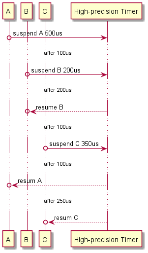
Figure 1. Multithreaded Delay Condition 01
To facilitate reading and further design implementation, Sugar has added some annotations to the above figure to provide a more detailed description of the multithreaded conditions, as shown in “Figure 2”:
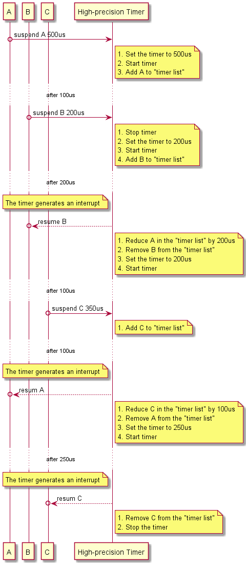
Figure 2. Multithreaded Delay Condition 02
To better illustrate, Sugar chose the recently thriving Microsoft Azure RTOS ThreadX as the foundation for this design. The goal is to output a generic method; the specific RTOS chosen is not important, as long as it supports multithreading, such as RT-Thread, FreeRTOS, etc.
In the figure, A, B, C, and High-precision Timer are four threads. The High-precision Timer thread has the highest priority but is not a timed callback; it is passively triggered. Next, we will discuss why the High-precision Timer thread has the highest priority and how it is passively triggered.
We know that when a thread waits for a semaphore using the WAIT_FOREVER method, if the semaphore value is 0, the thread will be suspended under this semaphore. We utilize this characteristic to achieve the “passive trigger” of the thread, specifically:
1. The initial value of the semaphore is set to 0
2. Release the semaphore once in an interrupt (i.e., increase the semaphore value by 1)
Thus, when an interrupt occurs, it can immediately wake up the thread suspended on that semaphore, completing the passive trigger of the thread. Once the thread transitions to the ready state, due to its highest priority, it will immediately preempt the scheduler for execution. When the High-precision Timer thread is awakened by the semaphore, it immediately performs a resume operation on the threads whose delay time has expired, thus completing the us delay for the threads.
Looking back at the three threads A, B, and C in the figure above, each line has two circles. The first circle from top to bottom on each line represents an active suspension due to delay, while the second circle indicates that after the time is up, the High-precision Timer thread resumes it for continued execution.
At this point, the method for reading the diagram has been basically explained. If we were to implement this in code, there is also a relationship between the “hardware timer and the High-precision Timer thread”. The label marked on the left side of the High-precision Timer in the figure indicates that the High-precision Timer thread resumes the threads whose delay time has expired because of an interrupt generated by the hardware timer. When discussing “passive triggering,” we mentioned the relevant principles; in fact, the far right of the above figure should include a column representing the “hardware timer” for better understanding of the principles. The reason it wasn’t included is that we need to consider “reentrancy”; this topic is quite complex, and including too much information can be overwhelming, so we decided not to draw the “hardware timer” column.
Code Implementation
To implement the blocking delay as described above, the code is divided into four parts:
1. Configure a us-level timer;
2. Create a function interface for us delay;
3. Have a High-precision Timer thread;
4. Have a test thread for a normal us-level timer callback.
Below, Sugar uses STM32 as an example to provide the code for each part.
us-Level Timer Configuration
1. Timer Initialization
It is most convenient to directly use the function generated by CubeMX without any modifications, as follows:
/** * @brief TIM9 Initialization Function * @param None * @retval None */static void MX_TIM9_Init(void){ /* USER CODE BEGIN TIM9_Init 0 */ /* USER CODE END TIM9_Init 0 */ TIM_ClockConfigTypeDef sClockSourceConfig = {0}; /* USER CODE BEGIN TIM9_Init 1 */ /* USER CODE END TIM9_Init 1 */ htim9.Instance = TIM9; htim9.Init.Prescaler = 215; htim9.Init.CounterMode = TIM_COUNTERMODE_UP; htim9.Init.Period = 65535; htim9.Init.ClockDivision = TIM_CLOCKDIVISION_DIV1; htim9.Init.AutoReloadPreload = TIM_AUTORELOAD_PRELOAD_DISABLE; if (HAL_TIM_Base_Init(&htim9) != HAL_OK) { Error_Handler(); } sClockSourceConfig.ClockSource = TIM_CLOCKSOURCE_INTERNAL; if (HAL_TIM_ConfigClockSource(&htim9, &sClockSourceConfig) != HAL_OK) { Error_Handler(); } /* USER CODE BEGIN TIM9_Init 2 */ /* USER CODE END TIM9_Init 2 */}Since we need to use the timer’s timing interrupt, we also need to set NVIC. This part of the code is generated by CubeMX in another file. For convenience, Sugar has merged it with the initialization function, as follows:
void bsp_InitHardTimer(void){ __HAL_RCC_TIM9_CLK_ENABLE(); HAL_NVIC_SetPriority(TIM1_BRK_TIM9_IRQn, 0, 0); HAL_NVIC_EnableIRQ(TIM1_BRK_TIM9_IRQn); MX_TIM9_Init();}Note that the initialization function is sufficient; do not enable the timer here, as the design requires the timer to be activated only when the delay function is called by the thread.
2. Function to Start the Timer
void bsp_DelayUS(uint32_t n){ n = (n<=30) ? n : (n-30); HAL_TIM_Base_Stop_IT(&htim9); htim9.Instance->CNT = htim9.Init.Period - n; HAL_TIM_Base_Start_IT(&htim9);}Note that it is “stop first, then start”; as mentioned above, in the case of “time overlap,” the timer that is currently delaying must be stopped first.
3. Timer Interrupt Function
/** * @brief This function handles TIM1 break interrupt and TIM9 global interrupt. */void TIM1_BRK_TIM9_IRQHandler(void){ /* USER CODE BEGIN TIM1_BRK_TIM9_IRQn 0 */ /* USER CODE END TIM1_BRK_TIM9_IRQn 0 */ HAL_TIM_IRQHandler(&htim9); /* USER CODE BEGIN TIM1_BRK_TIM9_IRQn 1 */ tx_semaphore_put(&tx_semaphore_delay_us); HAL_TIM_Base_Stop_IT(&htim9); /* USER CODE END TIM1_BRK_TIM9_IRQn 1 */}Here, we call the Microsoft Azure RTOS ThreadX API tx_semaphore_put() to release the semaphore, which is established during initialization (the code for establishing the semaphore is omitted).
Function Interface for us Delay
TX_THREAD *thread_delay_us;UINT tx_thread_sleep_us(ULONG timer_ticks){ TX_THREAD_GET_CURRENT(thread_delay_us) bsp_DelayUS(timer_ticks); tx_thread_suspend(thread_delay_us); return TX_SUCCESS;}Here, we define a global variable thread_delay_us, using TX_THREAD_GET_CURRENT() to get the thread calling the us delay. After starting the timer, the thread is suspended using tx_thread_suspend().
High-precision Timer Thread
extern TX_THREAD* thread_delay_us;UINT status;void threadx_task_delay_us_run(ULONG thread_input){ (void)thread_input; while(1){ tx_semaphore_get(&tx_semaphore_delay_us, TX_WAIT_FOREVER); if(thread_delay_us){ status = tx_thread_resume(thread_delay_us); } }}Here, the thread creation process is also omitted, and we provide the thread body: it completes the passive triggering of the thread with the semaphore tx_semaphore_delay_us and resumes the thread_delay_us thread.
Test Thread for us-Level Normal Timer Callback
#include "pthread.h"VOID *pthread_test_entry(VOID *pthread1_input){ while(1) { //print_task_information(); uint64_t now = get_timestamp_us(); tx_thread_sleep_us(100); printf("delay_us: %lld\r\n", get_timestamp_us() - now); }}This thread is established using the POSIX interface API; those interested in POSIX can refer to Sugar’s article “POSIX Interface of Azure RTOS ThreadX”.
Time Granularity Testing
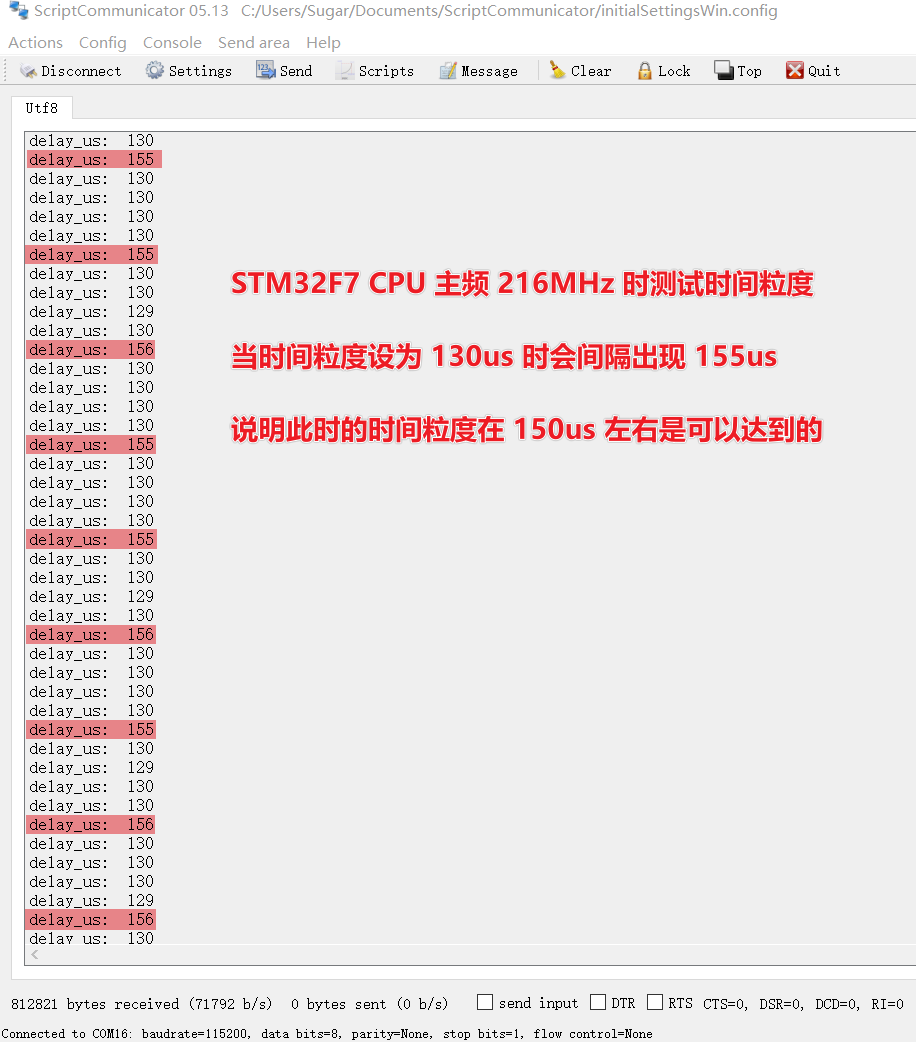
Figure 3. Time Granularity Test 1
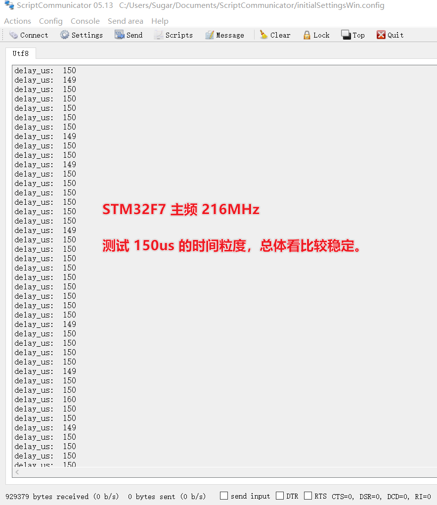
Figure 4. Time Granularity Test 2
ThreadX is said to achieve sub-microsecond context switching on a 200MHz MCU, and Sugar tested that the time granularity was relatively stable at 150us. This does not mean that ThreadX performs poorly; rather, the STM32F7 timer takes about 30us to start and stop, so the timer should not be turned on and off for precision less than 30us. However, for this design, we must have the timer’s on/off capability to handle possible reentrancy situations.
How does Sugar know that starting and stopping takes 30us? The reason is shown in “Figure 5”:
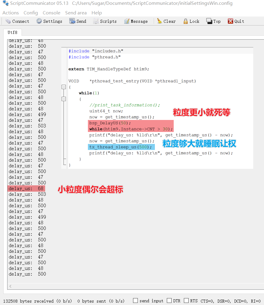
Figure 5. Time Granularity Test 3
Figures 1 and 2 were drawn using PlantUML. If you want high-definition images, you can generate them in SVG format. Those interested can add Sugar as a friend within 48 hours on the “About Me” page to request the PlantUML source files for self-generation. After a long time, Sugar may not be able to find them (as it is not in the habit of saving these files).