01
Introduction
The linear Hall sensor is a type of sensor that utilizes the principle of the Hall effect, which generates a potential difference as the magnetic induction intensity increases through its linear region. It is commonly used for measuring physical quantities, such as fuel gauges and liquid level meters.
The joystick used in game controllers also employs linear Hall sensors.
02
Principle
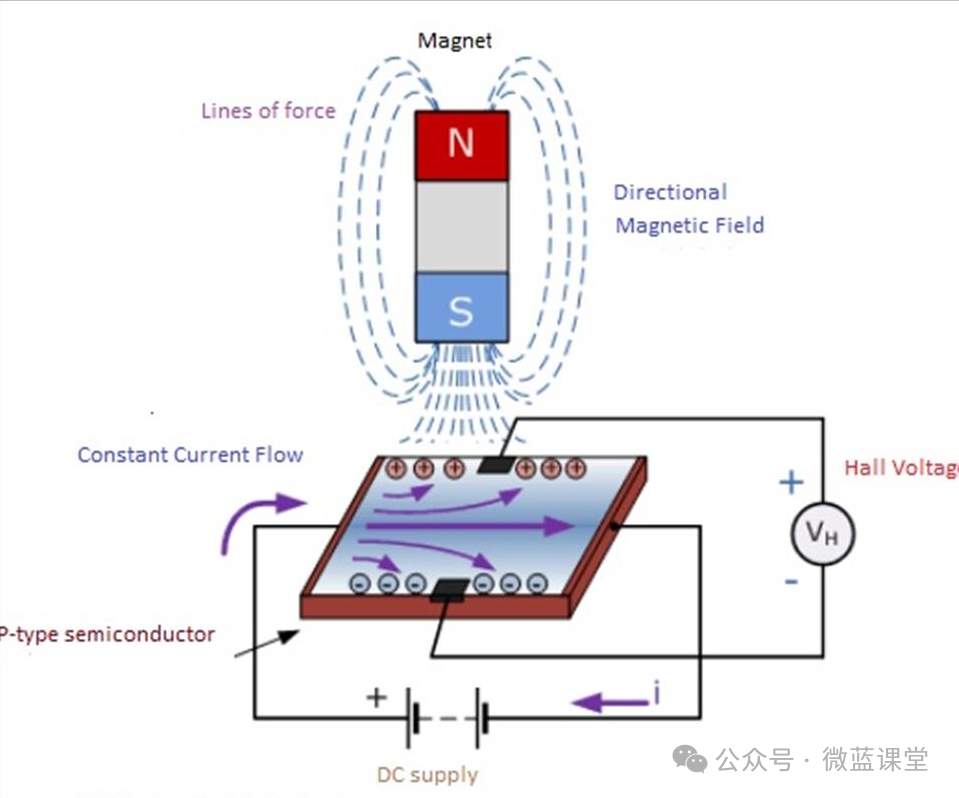
The Hall effect: When an electric current passes through a semiconductor material perpendicular to an external magnetic field, a potential difference occurs between the two ends of the semiconductor that are perpendicular to both the magnetic field and the current direction. In simple terms, when the current and magnetic field interact at a specific angle within the semiconductor material, a voltage is generated across the two sides of the material, known as the Hall voltage; this phenomenon is referred to as the Hall effect.
Formation of the Hall Effect
There are two main types of charge carriers in semiconductors: electrons and holes. In N-type semiconductors, electrons are the primary charge carriers, while in P-type semiconductors, holes are the primary charge carriers. When current flows through the semiconductor, the charge carriers move in a directed manner, forming an electric current. If a magnetic field is applied perpendicular to the direction of the current, the charge carriers will be affected by the Lorentz force.
For electrons in an N-type semiconductor, under the influence of the magnetic field, they will be deflected towards one side of the semiconductor due to the Lorentz force. As more and more electrons accumulate on this side, it becomes negatively charged, while the opposite side, lacking electrons, becomes relatively positively charged. This creates an electric field across the two sides of the semiconductor, with the force exerted by the electric field on the electrons opposing the direction of the Lorentz force.
As the electric field strengthens, when the force exerted by the electric field on the electrons balances the Lorentz force, the potential difference across the two sides of the semiconductor stabilizes, and this stable potential difference is the Hall voltage.
Working Principle of Linear Hall Sensors
A linear Hall sensor consists of a Hall element, a linear amplifier, and an emitter follower, outputting an analog signal. It is primarily used for measuring AC and DC currents and voltages. In certain magnetic fields, the output of the linear Hall sensor does not have discrete switching states but provides a signal proportional to the magnetic field strength. This output signal can be used as an analog output voltage, a pulse width modulation signal (PWM), or even sent as a modern bus protocol (SENT).
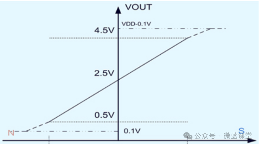
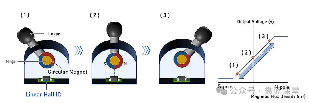
The output voltage of the linear Hall sensor is directly proportional to the magnetic field strength passing through it. Depending on the characteristics and strength of the magnetic field, its output voltage will either rise or fall. By observing changes in the magnetic field strength, one can determine corresponding positional data changes, with the output voltage having a fixed relationship with the polarity and strength of the detected magnetic field.
Applications of Linear Hall Sensors
Linear Hall sensors are primarily used for measuring physical quantities, such as current sensors. Due to the magnetic field present inside a powered solenoid, which is proportional to the current in the wire, the linear Hall sensor can measure the magnetic field to determine the magnitude of the current in the wire, allowing for the creation of Hall current sensors.
Additionally, linear Hall sensors can be used for displacement measurement. For example, placing two permanent magnets with the same polarity facing each other and positioning the linear Hall sensor in between results in a magnetic induction strength of zero at that point, which can serve as the zero point for displacement. When the Hall sensor undergoes Z-axis displacement, it outputs a voltage proportional to the distance of the displacement. By converting parameters such as tension and pressure into displacement distance, one can measure the magnitude of tension and pressure. Furthermore, they can be used in speed regulation, magnetic encoders, throttle pedals, and many other fields.
Input control joysticks also utilize linear Hall sensors, such as those found in game controllers and wireless devices. The main components include the joystick, hinge, circular magnet, and linear Hall IC. The Hall IC is placed directly below the hinge of the fixed joystick. As shown in the diagram (2), when the joystick is in the middle position, the boundary between the S and N poles of the circular magnet is directly above the Hall IC. This arrangement allows for linear output within a joystick angle range of approximately ±30°.
03
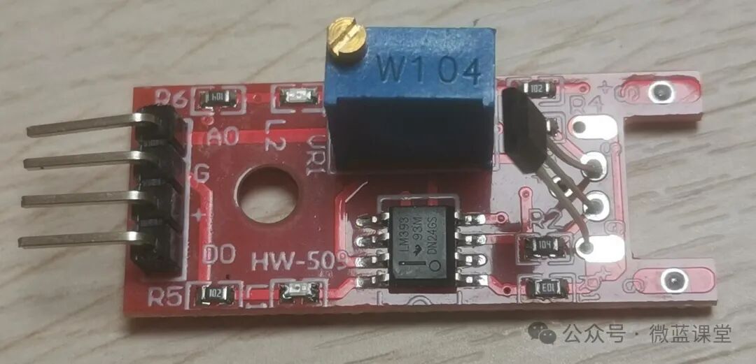
Wiring
- G: Power negative, connect to GND, gray wire
- +: Power positive, connect to 3.3V, red wire
- DO: Digital signal line, connect to P0, blue wire
- AO: Analog signal line, connect to P1, yellow wire
04
Program
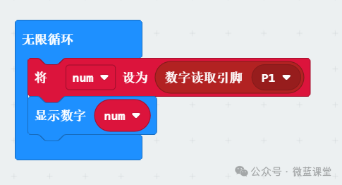
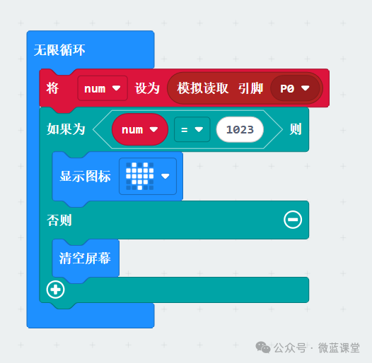
The following program can be used for magnetic field detection. If a magnetic field is detected, the L2 light will turn on, and the micro:bit will display a heart shape.
Simply connect to the DO port, with the digital output connected to the P0 pin, and store it in the variable sun.
If num equals 1023, display the heart shape.
05
Extensions
Hall sensors can be divided into:
- Linear Hall Sensors: Composed of Hall elements, linear amplifiers, and emitter followers, outputting analog signals.
- Switching Hall Sensors: Composed of voltage regulators, Hall elements, differential amplifiers, Schmitt triggers, and output stages, outputting digital signals.
Switching Hall sensors can be further divided into:
- Unipolar: Responds only to a single magnetic pole (N or S).
- Bipolar: Responds to both magnetic poles without distinguishing between N and S.
- Latching: Must cross the 0 Gauss point to activate the switch, requiring both N and S poles.
This linear sensor can also be used for latching switch tests: When the N pole touches the front of the sensor, it becomes 0; when the S pole touches the front of the sensor, it becomes 1. If the same pole is continuously touched, the digital output will not change.