AbstractThis paper presents a virtual prototype-based analysis framework to support comprehensive evaluation of distributed, networked automotive applications. The framework enables functional and timing verification, performance and reliability analysis, while reducing evaluation complexity.Additionally, the framework supports exploration of the design space of the entire system, considering target hardware/software and system environments.The proposed method narrows the evaluation gap between initial design and final system integration testing.Throughout the design process, the analysis supports designers in making effective design decisions. Representative automotive use cases demonstrate the applicability of the proposed framework. Advantages such as integration or automation capabilities of existing software prototypes are highlighted. Performance comparisons with widely used network simulation tools show the competitiveness of the proposed analysis framework.Categories and Topic DescriptionI.6.7 [Simulation and Modeling]: Simulation Support Systems; I.6.5 [Simulation and Modeling]: Model Development; C.2.1 [Computer Communication Networks]: Network Architecture and DesignGeneral TermsDesign, PerformanceKeywordsVirtual Prototype, System Simulation, Performance Evaluation, Automotive Development, SystemC1. IntroductionOver the past two decades, the number and complexity of software in vehicles have increased exponentially. In today’s high-end cars, more than 70 electronic control units (ECUs) are integrated in a networked environment, leading to an ever-increasing diversity of design options.During the design process, these alternatives must be evaluated to make effective design decisions.In addition to major decisions such as suitable communication technologies or topologies, there are various parametric alternatives that can significantly affect the behavior of the final system.Each decision must be verified to ensure it still meets functional, reliability, and performance requirements. Given today’s stringent demands, available resources must be utilized effectively; general resource overestimation is often impractical.Today, design decisions are primarily based on spreadsheet information, experiences from previous products, or analyses of reference system designs. The impact of design decisions on the actual system is verified in later design stages when physical prototypes are available, making changes to the overall system design nearly impossible or very costly.Another aspect is determining the impact of design changes, which must consider not only the actual system but also interactions with other system components in the networked environment.Therefore, a detailed overall system evaluation is required throughout the design process to bridge the evaluation gap between initial design and final system integration testing.Figure 1 highlights the enhanced classical V-model using the proposed method.
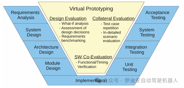 Figure 1: Virtual prototypes fill the evaluation gap between design and testing phases
The proposed evaluation framework uses virtual prototypes to assess the systems being developed during the design process.Virtual prototypes are behavioral models of the actual system.They enable hypothesis analysis before determining a design option. The proposed method allows for the evaluation and verification of rough system aspects using abstract models in the early design stages. As the design process progresses, the models are refined, becoming more accurate in reflecting the behavior of physical prototypes.Each refinement step is complex enough to perform the analyses required for the current design stage.When software prototypes are available, they can be integrated and tested with simulated system components.In later stages, when physical prototypes are available, virtual prototypes still provide benefits to the design process. Features such as pausing the entire system and monitoring each internal state are advantageous compared to debugging the system using physical prototypes. The deterministic behavior provided allows for the repeated simulation of test scenarios executed with physical prototypes. The evaluation overhead is generally lower compared to physical prototypes and HIL simulations.Collaborative simulation methods enhance the capabilities of simulation platforms, for example, by providing target code interpretation or physical environment simulation.Implementing this method presents the following challenges:• Supporting various system alternatives and system improvements• Reusing applications in different system scenarios• Integrating existing software prototypes• Designing and configuring simulations with controllable effortThe following paper presents solutions to these challenges. Section 3 focuses on the detailed evaluation framework and motivates the choice of SystemC [6]. Section 4 presents methods to support various system alternatives. Section 5 introduces configuration methods that can effectively handle the system variable space. Section 6 showcases the final design process and the graphical environment supporting users. Section 7 emphasizes the concept of integrating existing software prototypes. Section 8 presents use case evaluations.2. Related WorkThere are various approaches to evaluating different aspects of systems using virtual prototypes. In [8], virtual prototypes are used to evaluate the interaction of two communication technologies (Bluetooth and WiMedia Ultra Wideband). In [7], a FlexRay communication controller model using register transfer level (RTL) supports intellectual property (IP) development. Other simulation-based methods are introduced in [10, 14, 2]. All these methods focus on dedicated system components and specific evaluation goals, generating optimized virtual prototypes for dedicated analyses. They do not target a general reusable evaluation infrastructure, neglecting the scalability and reusability of models. The focus of these methods is not on the entire system and the goal of iteratively implementing a comprehensive simulation platform.[4] presents an extension of SystemC that supports the simulation of embedded systems and surrounding network environments.It does not consider supporting various system alternatives or efficient simulation configurations. Specific extensions can be integrated into our evaluation framework, but the current transaction-level modeling (TLM) concept is sufficient.In addition to research methods, there are many commercial solutions, such as [19, 20, 16], that allow for the assembly of virtual prototypes based on components.These tools assemble detailed IP components, instruction set simulators (ISS), and interconnect networks to simulate systems.Most of these tools do not allow for very abstract architecture exploration, as the provided IP blocks already depend on technology and lack the ability to refine models. Another aspect is the integration of application software.In most tools, software must be cross-compiled to run on ISS, which reduces flexible hardware/software partitioning.Regarding communication parts, there is a range of network simulation tools, such as [15, 17, 18]. These tools primarily focus on building networks for simulation. Discrete simulations can be extended to cover on-chip resources, such as shared processing resources. On the other hand, SystemC originated in the hardware description domain and has evolved into a system-level modeling language.In the proposed method, SystemC is prioritized over existing network simulation tools.Other methods suggest using analysis frameworks to evaluate different isolated system aspects.In [3, 5, 9], timing and predictability analyses of the FlexRay bus system are introduced.These methods are based on analysis methods such as real-time calculus, ILP, or mathematical models.The commonality of all methods is that the system behavior must be transferred to the analysis model, for example, for real-time calculus methods, arrival and service curves must be derived.Mathematical models specifying access times must be defined for [5].Therefore, the applicability of these methods is limited to evaluating isolated system aspects.Most of the mentioned methods focus on evaluating dedicated system aspects or platform-related code, neglecting the entire system. The analyzed systems are modeled at a fixed level of abstraction, without considering the ability to refine models and adapt to system changes. They do not consider reusing specified system components in different evaluation scenarios.3. Evaluation FrameworkThe proposed evaluation framework is based on a set of behavioral models called virtual prototypes.Virtual prototypes can evaluate hardware/software systems without physical prototypes.With the help of a software-based simulation kernel, the required system components can be simulated.The event-driven simulation language SystemC can create virtual prototypes to describe the entire system or interact with developed software implementations.Using these mechanisms, the functional and timing behavior of combined hardware/software systems can be simulated. Language features such as modules or ports encourage layered, composable designs.Based on the fact that actual software and hardware are described by software-based simulations, hardware/software partitioning can be flexibly changed and explored.Both software and hardware timing can be modeled and improved during the design process. Methods such as [13] allow estimating the execution time of software components based on target architectures and annotating it in the source code. This enables timing software simulations to be conducted from very abstract levels to detailed architecture-related levels without simulating execution platforms.With TLM capabilities, SystemC provides extensions to system-level modeling. TLM2.0 supports modeling communication beyond specific hardware implementations at various abstraction levels (e.g., cycle-accurate, approximate timing, loose timing, or untimed).The inherent concepts of unified interfaces and sockets enhance the interoperability of modules. The availability of different collaborative simulation methods, for example, integration in driving simulations similar to [21], allows users to dynamically interact with virtual prototypes, supporting the choice of SystemC. On the other hand, an increasing number of IPs already provide additional SystemC simulation models.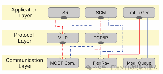
Figure 2: Sketch of the three-layer approach
A general advantage of virtual prototypes is that only the necessary aspects for evaluating behavior need to be implemented.This leads to evaluation-oriented implementations, which are often simpler than actual system implementations. For example, the developed Media Oriented Systems Transport (MOST) model provides implementations for asynchronous, synchronous, control, and isochronous data exchange.It simulates a MOST frame that circulates around the MOST ring and is clock-controlled by a timing host at typical MOST frequencies.The actual MOST network would forward this frame bit by bit through the physical layer (most likely plastic optical fiber (POF)). This aspect is neglected in the implementation, and the complete frame is forwarded with fixed delays on the physical bus segment. Introducing bit-wise simulation does not benefit the current evaluation and significantly increases simulation runtime and implementation complexity.Combining different communication systems for automotive applications is the main focus of the presented analysis framework. The current implementation covers network technologies such as MOST, FlexRay, half-duplex Ethernet, and communication models based on abstract TLM-2.0. Different communication protocols are implemented on top of this communication layer. In this paper, we focus on the TCP/IP stack and the MOSTHigh protocol (MHP). Within previous industrial project scopes, different applications have been integrated. Their range spans from dedicated industrial use cases (e.g., traffic sign recognition (TSR) or stereo depth map (SDM) applications) to a set of generic traffic generators. Traffic generators can be used if only the communication characteristics of the applications are provided. This is important if the applications cannot be disclosed due to confidentiality reasons or if the effort to port the applications onto the virtual prototype is not worthwhile (e.g., if only the interference of other applications on the shared bus is considered).The resulting challenge: To facilitate the evaluation of various systems, different parts of the simulation must be reusable. The same application should be usable with different communication technologies without changing the application. Parameters of the system (e.g., communication bandwidth, internal buffer sizes, or host system performance characteristics) should be adjustable without redesigning the simulation. If certain parts of the system must be changed (e.g., different versions of communication protocols or different levels of abstraction), the replacement should be limited to those parts. Section 4 details the methods to address these topics.4. Virtual Prototype StructureThis section focuses on the development concepts of a configurable, reusable simulation platform. These concepts include a layered approach using standardized interfaces, addressing methods, and parameters.
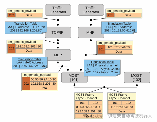 Figure 3: LAA in TCP/IP, MHP scenarios
4.1 Three-Layer ApproachThe virtual prototype adopts a three-layer approach, including the application layer, protocol layer, and communication layer, as shown in Figure 2. Modules at different layers are interconnected via TLM-2.0 interfaces. Since the modules communicating between layers use the same standardized interface, lower-level modules can be exchanged.The application layer contains data receiver or data source modules. All modules require the TLM-2.0 interface of the lower communication modules to transmit and receive data, as indicated by the solid ellipses in Figure 2. The intermediate layer provides protocol mechanisms. Modules in this layer provide TLM-2.0 interfaces to the upper layer and request TLM-2.0 interfaces from the lower layer. They process and forward incoming data, most likely by adding protocol-specific information to the payload, such as TCP/IP headers and trailers. However, in cases of retransmission or segmentation, this layer can operate independently of the application layer. The lowest layer implements the actual communication technologies, such as MOST or FlexRay. These modules provide TLM-2.0 interfaces and handle data exchange between different devices. This approach allows mapping one application to different communication technologies since all technologies provide a standardized interface. Additionally, various protocol implementations can be connected as they provide and require the same interface. Figure 2 highlights different alternative communication paths. The same TSR module uses the MHPort or TCP module of the protocol layer. The SDM application module can be mapped to the protocol layer or directly to the communication layer. Traffic generators can be used with the FlexRay bus or abstract TLM message queues, illustrating the interchangeability of communication modules.4.2 Logical Application Addressing MethodWhen changing communication technologies, heterogeneous addressing schemes can cause issues. The TLM-2.0 interface uses a generic payload structure to exchange data.This structure allows specifying data length, actual data pointer, and a target address of 8 bytes in length.The problem is that different protocols and communication layers use different addressing formats, for example, TCP/IP uses IP addresses and port numbers, MHP uses vectors of function blocks, instance IDs, function IDs, and operation types, and FlexRay bus uses Socket IDs.Using these physical addresses in applications would eliminate the flexibility of using applications with different communication layers.To regain this flexibility, logical application addressing (LAA) is introduced.LAA identifies communication associations, meaning that if two applications send data to the same target device, different LAAs are used.Whenever a module requires a physical address, it provides a translation table that decodes the LAA into a physical address and vice versa.The corresponding physical address is only used for communication modules or encapsulated in payload data.This means that all applications and protocol layer modules exchanging data using the TLM-2.0 interface use logical application addresses.Only physical addresses exist in the communication layer.If two communication associations must map to the same channel, both logical application addresses will map to the same physical address.Figure 3 shows different translation tables for TCP/IP, MHP scenarios.Both applications use different LAAs to identify the communication destination.If the involved communication modules require physical addresses, a translation table is provided.For example, the TCP/IP module requires a physical address to generate TCP/IP headers.After generating the header and encapsulating the data, the frame will be forwarded using the logical application address.Finally, both messages map to the same physical channel with the same physical target address.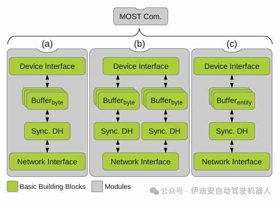
Figure 4: Assembly of basic building blocks
4.3 Modular Substructure ApproachThe three-layer approach combined with LAA provides the first level of flexibility. Different applications can be mapped to various protocols and communication mechanisms. To achieve the flexibility required for evaluating various system alternatives and variants, the functionality of different parts is further divided into submodules.Different communication, protocol, and application modules are assembled by connecting the required submodules, referred to here as basic building blocks. This method is highlighted with the MOST model.The functionality description of the MOST communication module consists of a set of 17 blocks, each implementing basic tasks. For each type of MOST channel, for example, there is a dedicated building block for extracting data from frames and storing it in buffers or vice versa. By assembling MOST modules from these basic building blocks, different numbers of channels can be created, such as multiple synchronous channels, comparing Figures 4(a) and (b). Thus, different virtual prototypes can be achieved simply by changing the block assembly.Another aspect is that the functionality of individual blocks can be implemented in different ways. For example, an AMOS device contains a buffer block for storing received or sent data. In the current model, there are two basic block implementations with different internal memory representations and allocation algorithms. Both implementations use a common interface, making them interchangeable. When these blocks are swapped in the assembly, the behavior of the device changes, comparing Figures 4(a) and (c).Using functional partitioning, the same module can be described at different levels of abstraction. If more detailed modeling is detrimental to evaluation goals, more abstract blocks can be used to improve simulation performance. If a subsequent evaluation requires more detailed functionality or timing behavior, the basic blocks can be replaced with more accurate implementations.In addition to the flexibility of assembling basic building blocks, most blocks provide a set of parameters that allow behavior adjustment. The 17 basic building blocks of the MOST module provide a total of 48 configurable parameters. Most of these are used to personalize devices, such as device addresses or provide assembly-related information like LAA translation tables. Other parameters affect system behavior and allow for evaluating more alternatives, such as buffer sizes, interrupt rates, or provided bandwidth. Using this set of parameterizable basic building blocks, various systems can be specified. The resulting challenge: Such high flexibility is not suitable for assembling and configuring the required systems in source code. Every time a parameter is changed or modules are swapped, the entire system must be recompiled. Especially when a large number of simulation runs must be executed and parameterization only varies slightly (e.g., to find optimal system parameterization), the total simulation time will increase significantly. Additionally, writing a TopModule and passing all parameters with the help of constructors can be a very time-consuming task. The following Section 5 presents system configuration methods to address these challenges.5. System ConfigurationThe evaluation framework uses an XML-based configuration method. The composition and parameterization of basic building blocks are in separate configuration files. Information from this file is used during execution to assemble and configure the system. With this method, different system alternatives can be simulated by simply changing the configuration file without recompiling the system. Figure 5 illustrates this process. The basic blocks introduced in the previous section are summarized in a block library. Each individual block in the block library is registered in a central block registry. The block registry is a lookup table where each basic building block is associated with a unique ID and a function for instantiating the block, similar to a factory method. The second key element is configuration management. The task of this class is to parse the configuration file and provide the information contained to the simulation platform. After parsing the XML file, all included blocks are instantiated. Thus, each block ID is looked up in the block registry, and the factory method is called to return the created object. Configuration management stores references to the created objects based on the object IDs specified in the XML file. The factory method passes an iterator that allows stepwise traversal of the configuration parameters associated with the current block. Each parameter contains a unique ID, a data type, and a value for initializing member variables. Parameters can be cascaded and complex data structures can be built. The responsibility for interpreting configuration parameters and assigning them to the correct variables lies with the basic building blocks. Configuration management only provides unified access to the information. After instantiating all required blocks, the blocks are interconnected. To avoid the need for dependency analysis of blocks and allow for circular dependencies between blocks, instantiation and linking are completed in two separate steps. Configuration management iterates over the linking of blocks, calling the linker method and passing references to the target blocks. Block instances use this information to establish connections. The objects are responsible for correctly converting unified references and establishing connections in the correct manner. In the current simulation platform, ordinary object pointers, TLM sockets, and SystemC ports are used. By typecasting common block references, configuration errors in the XML file can be detected and simulation terminated. After executing these two steps for each basic building block, configuration management contains interconnected block instances assembled into a complete system. This system simulation instance is used to execute simulations.
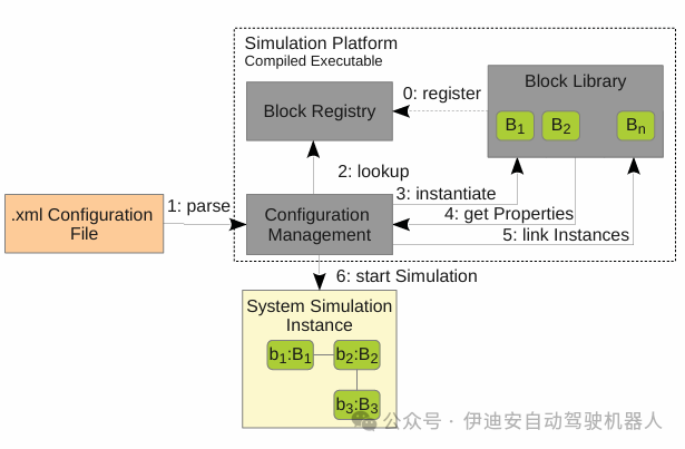 Figure 5: Virtual Prototype Configuration Method
Changing parameter values only requires modifying the XML file. Simulations can be re-executed without recompilation. Additionally, modules can be swapped in the XML file. Various XML binding tools for different programming languages exist, making it easy to create powerful test generators. XML instance specifications are used to automatically generate code that allows parsing and serializing XML files. In different analysis scenarios, Python scripts are used to automatically generate a large number of XML configuration files.The resulting challenge: Each basic building block contains similar factory and linker methods. This repetitive functionality is best suited for automatic code generation. The information, parameters, and links specified for this step can be additionally used to generate XML configuration files. Graphical tools and code generation are introduced in Section 6.6. Graphical Tool SupportTo reduce the overhead of designing virtual prototypes, different code generation steps are used. As mentioned in the previous section, virtual prototypes contain repetitive code templates, which are best suited for code generation. Automatic code generation targets two different domains.First, block skeletons are generated, creating member variables, factory and linker methods, and function stubs. These skeletons are compiled to create simulation executables. The second task covers generating XML configuration files, which are used at runtime to assemble the simulation platform.The basis for code generation is a set of UML diagrams. The Eclipse Papyrus framework serves as the tool environment. The original framework is extended by Eclipse plugins to complete code generation. Additionally, UML is extended through custom UML configuration files.To generate the block library, UML class diagrams are used. Each block is presented as a single class containing member variables and functions. Custom UML configuration files allow specifying SystemC features. It can be specified whether the generated class is an sc module, sc channel, or whether functions should be declared as sc threads. The second configuration file provides the ability to specify evaluation framework-specific information. Member variables can be associated with IDs to allow parameterization of that variable using XML files. Additionally, associations with IDs and types can be extended. Types currently cover pointers, sc ports, or TLM sockets. Using all this information, block skeletons can be generated. Consideration is given to class inheritance, variable and function declarations, and their visibility. Factory method implementations and parameter handling are generated. The required information (e.g., types and associated IDs) is specified by the UML diagrams. Figure 6 shows the UML class diagram of the basic building block M PMSMEPAdapter. The complete class is constructed as an sc module, creating a SystemC module. It can be seen that the first three properties are constructed as vp properties. This construction type indicates member variables created using XML file configuration. This class is associated with other classes or interfaces. Each association creates a resolver entry in the linker method. Specialized construction types allow specifying the type and ID of the associated elements. Using this information, linker methods can be generated. Additionally, all member variables and function declarations are generated. In the current implementation, only function declarations and empty function stubs are generated. Code generation does not cover any actual functionality.Graphically specifying the actual functionality requires as much work as solving the same task programmatically.Therefore, only function stubs are generated, and manual implementation is performed. There is a set of mature tools, such as MATLAB/Simulink, that support functional code generation. The outputs of these tools can be used to implement function stubs. To allow for automatic code generation on one hand and manual code extension on the other, merging techniques known in software versions are used. For each generated code, an ancestor file is maintained, allowing detection of differences between new versions of generated code, user modifications, and previously generated code. The merging functionality resolves non-conflicting differences and prompts the user to manually resolve conflicting changes. This allows for comfortable parallel editing of automatically generated and manually extended code.
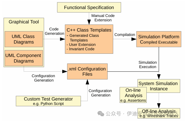 Figure 6: UML Class Diagram of Basic Block
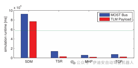 Figure 7: Result Analysis Process
The second task supported by graphical tools is generating XML configuration files. For each block, UML class diagrams specify parameters, associations, and unique IDs. By generating instances of these classes, assigning parameter values to specified parameters, and interconnecting instances, XML configuration files can be described. The Papyrus framework provides composite structure diagrams for this task. With the help of these two diagrams, block skeletons of the block library, block registry, and XML configuration files can be automatically generated.With code generation support, the additional coding overhead caused by the XML configuration method is eliminated. All code required to initialize properties and link blocks is automatically generated, allowing users to focus on implementing block functionality. The current scope of the simulation platform covers 55 blocks, totaling 212 properties and 87 links.6.1 Final Analysis ProcessThe concepts of graphical specifications, XML configuration files, and precompiled simulation platforms yield an analysis process, as shown in Figure 7. In the first phase, class diagrams containing parameters and associations are specified graphically. In the next step, block skeletons with function stubs are generated. Afterward, users manually implement the required functionality and compile the complete simulation platform. Separating implementation, system configuration is specified as a composite structure diagram and generated as an XML file.The compiled simulation platform and the generated XML file are used to simulate different systems. By changing various aspects in the composite structure diagram, for example, changing parameter values or associations, different systems can be simulated. In addition to graphically generating configuration files, test generators can also be used to generate test cases.System evaluation has two general approaches. For online validation, it checks whether specified properties are met during simulation runs. This can be accomplished using assertions included in the simulation platform.Standard C++ assertions can be used to test basic value-related specifications.Assertions based on finite linear time temporal logic (FLTL) (similar to the methods proposed in [12]) allow checking one or more complex temporal specifications.During simulation, it will be checked whether assertions are violated; if violated, the simulation ends and an error report is generated.If offline validation is required, the simulation will create trace files that record system behavior.After simulation, the correct behavior of the system will be verified based on the recorded trace files.This can be done by comparing the system behavior with a set of requirements, golden references, or previous simulation traces.If it is necessary to monitor a certain aspect of system changes and their impact, it is useful to compare with previous system traces, similar to the reliability analysis proposed in [11].In the current simulation framework, there are different modules that can generate various trace files.Some traces are suitable for third-party tools, such as Wireshark or OptoLyzerSuite (Figure 10), allowing existing tools to analyze the behavior of the simulated system.Other modules generate custom trace files that can be read by users or used for post-processing with proprietary tools, such as Python or MATLAB scripts for analyzing or visualizing traces (Figure 9). Users can easily determine the observation scope by adding appropriate modules in the composite structure diagram.The trace scope strongly affects simulation performance.7. Integration of Software PrototypesIt is necessary to integrate developed software into virtual prototypes, especially in later design stages. This is very useful for testing developed software or improving the behavior of the virtual system to reflect the physical system. In the embedded systems domain, software is often written in ANSI C. Since ANSI C is similar to C++, integration is straightforward, but some challenges arise. The main challenge is encapsulating ANSI C code to create multiple independent instances. Since the virtual prototype describes the complete system, ANSI C code is most likely executed on different virtual devices. This means multiple instances of ANSI C code exist simultaneously in the simulation environment. Currently, three different methods have been implemented. For small software implementations, ANSI C functions can be encapsulated in C++ class definitions. The complete ANSI C code is included in the C++ class definition; see Figure 8(a). Thus, the provided interface is added to the corresponding class. The original code needs to be modified for the required interface. Global function calls or variable accesses must be mapped to class member functions or variables. With macros, integration can be achieved by defining replacements at the beginning of the file. For example, if ANSI C code requires a global function to send data, this call will be replaced with a call to the external class that provides the required member function. MHP is integrated in this way. If the software is more complex, this method becomes impractical. The number of files and their interdependencies complicate the method. Another approach is to encapsulate ANSI C code into different host system processes. This way, all functions and global variables are encapsulated in one process.By creating multiple processes, multiple instances can exist in the virtual system.Since different processes manage their own address space, there is no interference between multiple instances. To interact with the simulation environment, inter-process communication (IPC) of the host system is used, see Figure 8(b). Function calls, parameters, and return values are serialized and transmitted via IPC. This establishes loose coupling between the simulation and ANSI C code.
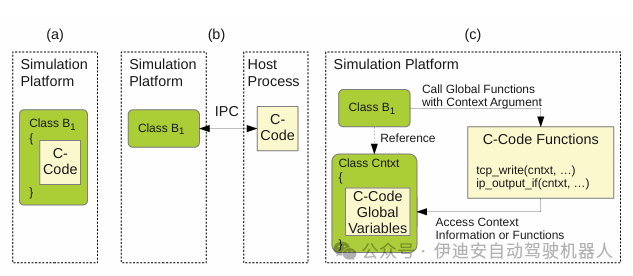 Figure 8: Integration of ANSI C Code
If tighter integration is required, direct integration is beneficial. This occurs when frequently calling simulation-related instructions or when the software code carries timing information annotations, see [13]. To support multiple instances, a context object must be created that contains all global variables from the ANSI C code. ANSI C functions remain global within the simulation platform, simply included with the extern keyword. Whenever a function needs to access a global variable, it calls the relevant setter or getter function in the context object. Thus, each function must know the current context object it is associated with. This is achieved by passing a pointer to the context object as a parameter to each subsequent function call. The lwIP stack is integrated in this way. When a basic building block (usually a C++ class) wants to transmit data via the lwIP stack, it only needs a reference to the lwIP context object. This reference is forwarded throughout the stack and is used to access context-sensitive information in the data processing chain. The original lwIP functions are modified so that each function has a lwIP context parameter. After data processing within the stack is completed, the transfer function in the context object is called, using the standardized TLM-2.0 interface to send data. As mentioned earlier, the interfaces between layers are implemented via TLM-2.0. The simulation platform adopts a top-down approach, meaning that the top-level module must poll the lower-level modules for data presence. On the other hand, the lwIP stack provides a callback function that should be called when data is present. To arbitrate between these two strategies, the lwIP context implements a SystemC process that polls the communication network. If data is received, the lwIP callback function is called. In addition to managing context-sensitive information, the lwIP context also implements the required OS functionalities, such as thread creation, semaphores, and message boxes. This approach has a drawback. ANSI C functions remain global within the simulation platform. If different parts of the simulation platform use libraries with the same declarations, linking issues arise. For example, if the standard TCP/IP library of the host system is applied to inter-process communication, problems will occur. In the current implementation, this issue is resolved by moving the socket communication of these modules to external libraries accessed from the simulation platform.8. EvaluationIn the following sections, we will present the developed infrastructure based on industrial and artificial use cases. This paper will not detail a single evaluation result but will provide different evaluation goals and considerations, such as evaluation goals and considerations regarding simulation performance. The aim is to highlight the potential of the proposed method and enhance confidence in the developed simulation models.Performance Evaluation.One application area is system performance evaluation. With virtual prototypes, system performance characteristics can be evaluated long before physical prototypes are available. This information can be used in the design process to make effective design decisions early on. For example, the current requirements of automotive systems are to route data from consumer devices (such as smartphones or laptops) through in-vehicle networks. Most available standards in this area use IP-based protocols. Therefore, IP-based protocols have entered automotive networks. In both automotive networks and IP-based communication, design experiences have accumulated over the past few years, but the combination of the two presents new design challenges. When using both protocols simultaneously in previous projects, the developed virtual prototypes can be reused during combined system evaluations.In the following use case, a TCP/IP connection is established through the MOST network between a transmitter and a receiver device. Designers will face the following questions: How will the two protocols affect each other since they share a common communication channel? What parameterization can guarantee fair bus allocation? Is it possible to achieve fair bus usage through parameterization, or are different topologies required? All these questions can be addressed with virtual prototypes. In the following use case, the virtual prototype consists of a transmitter and a receiver device. The transmitter device establishes a TCP/IP connection via MOST Ethernet Protocol (MEP) and simultaneously establishes an MHP connection. The receiver device provides limited buffer space, and the application reads this space at a fixed rate.By providing this software timing abstraction, inherent communication stack timing, and bus timing, different transmissions can be simulated and final performance monitored.With virtual prototypes, it can be discovered that the proposed configuration leads to high bus utilization for MHP. In the worst case, this results in scarcity of TCP transmissions. This is based on faster retransmissions and the size of the packets used.If both protocols encounter message loss, MHP recovers faster and allocates the shared channel more quickly. Thus, TCP cannot share the channel equally.One option is to increase the polling cycle in the receiving device to prevent message loss, but this only applies to dedicated scenarios where the buffer is the bottleneck. Another method is to change TCP retransmission and receive window parameters and increase MHP packet gaps. These different designs can be simulated using virtual prototypes, and final performance can be monitored.Additionally, different traffic shapes can be used to validate average transmission performance.Figure 9 shows a trace excerpt created with the initially proposed parameterization. Physical frame utilization (a) is displayed as bar charts, representing the payload size contained in a frame at a given point in time.Similarly, outgoing messages of TCP/IP and MHP protocols are plotted as bar charts according to their sizes.Figure (e) shows the times when messages are discarded due to limited receiving buffer space.It can be seen that both MHP (c) and TCP/IP over MEP (b) start transmitting data through a shared channel providing adequate bandwidth (a).Both transmissions experience message loss (e), while MHP recovers quickly, and TCP enters retransmission timeout, indicated by the pause at the end (b).The use case illustrates how the virtual prototype method provides detailed insights into system behavior.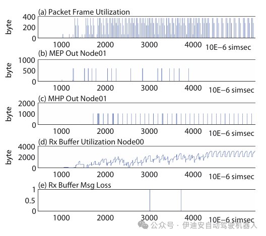
Figure 9: TCP/IP, MHP Trace Excerpt
Application Validation.This section demonstrates how to analyze applications at different levels of abstraction. The traffic sign recognition (TSR) application is distributed across different computing nodes, exchanging data using a communication network. In the first evaluation, the application is mapped to an abstract TLM-2.0 channel, meaning that application data is transmitted once, and each transmission has an estimated time. For the TSR application, data mainly consists of image frames. To validate the behavior of the application, virtual tests need to be performed, testing the algorithm with different input scenarios (e.g., multiple traffic signs in one frame). Different parameters of the testing algorithm, such as the size and position of the area of interest, the radius of detected circles, or the training data of the support vector machine. All scenarios are repeatable, data can be paused at any time, and all internal states are accessible, improving the functional evaluation of the application and replacing the usual worst-case assumptions. In addition to functional validation, aspects such as the duration between capturing traffic signs and displaying classified speed values are also evaluated. Different system parameters, such as application interrupt rates or communication delays, are adjusted and time effects analyzed. During the design process, the abstract communication module will be improved according to the target bus technology (e.g., MOST bus).Subsequently, the same evaluation will be performed, but this time with more accurate communication behavior. The protocol mechanisms of the bus technology (such as packet structures, segmentation, retransmission behavior, or channel timing) will all be taken into account.Additionally, technology-specific tools will be used to analyze bus traffic. Figure 10 provides a sketch of two evaluation scenarios. In the upper part, the TSR application uses an abstract message queue based on TLM-2.0. A custom logging mechanism (such as video or text output) is used to monitor the simulation. In the second part, the MOST bus and corresponding protocols are integrated into the simulation. Technology-dependent logging tools, such as the OptoLyzer tool suite, are used.Next, the performance of the virtual prototype should be examined more closely. Figure 11 shows the simulation runtimes of different application scenarios. The measurements were conducted on a simulation host with an Intel® Core™ i5-750 processor, 8GB RAM, and Linux Kernel 3.2.0. The presented applications cover stereo depth map (SDM) calculations, the introduced TSR application, and traffic generators communicating via MH or TCP. Each scenario simulates 60 simsec (simulation seconds) using appropriate channels of TLM-2.0 message queues or the MOST bus. The TSR scenario is an isochronous channel for camera data, MHP for cropping signs, and a control channel for classifying speed values, see Figure 10. The SDM application uses very complex calculations, and in actual embedded systems, part of the calculations uses dedicated hardware, so the simulation duration is longer than the simulation time.Other use cases are much faster than simulation time, allowing for an extended testing space compared to physical prototypes, such as executing longer virtual test drives.Additionally, it can be seen that adding MOST bus simulation increases simulation duration, as more parallel events must be simulated.Another significant parameter affecting simulation performance is the frequency at which the application polls the underlying communication network. The shorter the polling cycle, the more events are generated.The large parameter set makes it difficult to provide a general degree of performance for the developed simulation platform.Table 1 shows the performance characteristics of different simulation scenarios. These values represent averages, with an average coefficient of variation of about 1.47%, related to runtime. When executing SDM without the MOST network, only a few events occur. This is based on the fact that all computations related to a single image aggregate into one event. Thus, events are proportional to the exchanged images. The last column shows the relationship between simulation time and runtime; the smaller the number, the faster the simulation. Only the time required for SDM simulation is greater than the simulation time, characterized by values greater than one.When adding MOST bus simulation, the SDM use case sees the most significant increase in events.This is based on the fact that the amount of data transmitted by the application is the largest and requires further segmentation for transmission via the MOST bus. For the protocol simulations of TCP/IP and MHP, the increase in events is not as significant, as the protocols have already segmented the data into appropriate sizes.
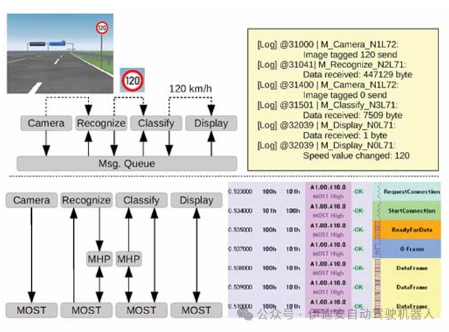 Figure 10: Structure and Trajectory of TSR Scenario
Figure 11: Runtime of Different Applications
Protocol Validation.Virtual prototypesnot only support application development but also communication protocol design. The MOST and FlexRay specifications contain different state diagrams to specify the behavior of communication controllers.To verify correct behavior in the early design stages, these state machines are implemented in virtual prototypes.This allows for evaluating protocol designs in different bus scenarios.One of the most beneficial evaluations is the design of timers.Both specifications provide ranges for different timers, for example, MOST specifies the maximum duration for device startup.With virtual prototypes, different bus configurations, numbers of devices, device propagation delays, or timer configurations can be simulated.It can be verified that timer boundaries are not violated in all scenarios. Since the configuration space is still large, it is not possible to verify every parameter combination, so techniques such as extreme case analysis are applied.INET/OMNeT++ Comparison.The developed virtual prototype is compared with the TCP/IP model in the INET/OMNeT++ framework [1]. First, the functional equivalence of the two models is compared. Thus, the sender and receiver devices are connected to a bandwidth-limited bus. Scenarios of 100Mbit/s and 60Mbit/s are simulated. The upper left part of Figure 12 plots the bytes transmitted.The red graph shows the amount of data in the INET model, while the blue graph shows the number of bytes in the SystemC-based virtual prototype.It can be seen that these graphs are almost identical, increasing confidence in the model. The small deviations are based on the fact that the two models have different internal structures.For example, the SystemC-based model simulates the polling mechanism between the TCP/IP stack and the communication controller, mirroring a transceiver chip that has non-interrupt-driven I/O or fixed service loops.The INET model does not have such a polling mechanism and triggers the protocol when data is received. The upper right graph shows the distribution of TCP/IP frames in the 60Mbit/s scenario. TCP/IP frames are divided into data frames and separate management frames, such as acknowledgments from the receiving device. It can be seen that both simulations have equal distributions, indicating that the behavior of the two models is the same. Comparing the two trace files in Wireshark supports this conclusion.
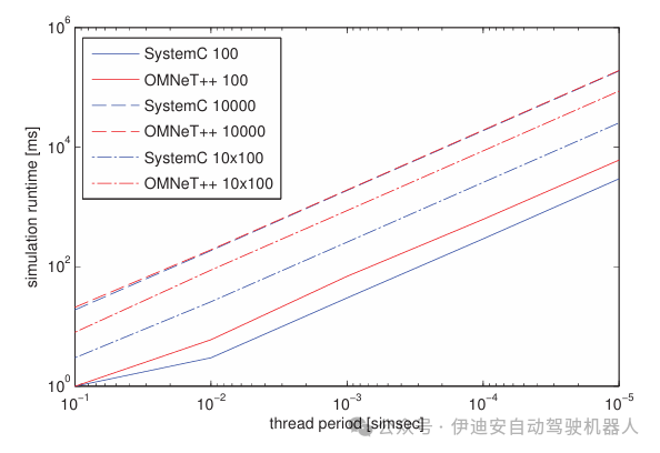 Table 1: Performance Summary of Different Models
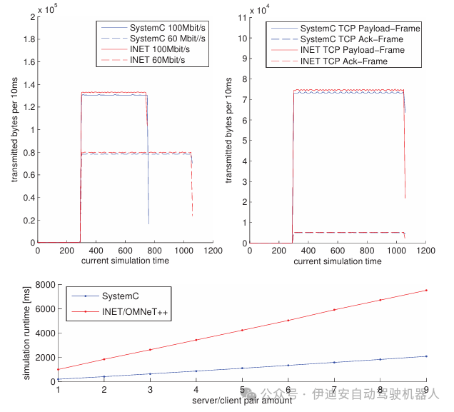 Figure 12: Functional and Performance Comparison of SystemC and INET/OMNeT++
In the second part, the simulation runtimes of the two simulations are compared. The sender/receiver scenarios are simulated in parallel multiple times. The monitored simulation times are displayed in the lower part of Figure 12. It can be seen that the performance of the proposed virtual prototype is competitive with the INET/OMNeT++ model. In both models, the available logging/tracing mechanisms have been disabled. The OMNeT++ simulation is executed using a command-line user interface, minimizing the overhead of the user interface. Both measurements were conducted on the same simulation host as in the previous section. The simulation time is the average of 100 repeated simulation runs, showing an average coefficient of variation of about 0.82%.
In addition to comparing the performance of different models, the performance of the simulators used is also compared. Therefore, a synthetic module was implemented, consisting of a loop that periodically executes a set of additions. The amount of additions and the duration of the cycles are configurable. Similar to the previous comparisons, all simulations are executed via the command-line user interface, and logging is disabled. Figure 13 shows the results of three different configurations. The execution cycles for each scenario are 0.1, 0.01, 0.001, 0.0001, 0.00001 sim seconds, with a total simulation time of 100 sim seconds. The first scenario OMNeT++/SystemC100 executes 100 addition blocks per cycle, while the second scenario executes 10,000 addition blocks. The OMNeT++/SystemC10x100 scenario simulates 10 modules, each executing 100 addition blocks in parallel. Figure 13 shows the monitored runtime. It can be seen that the SystemC simulator is competitive with the OMNeT++ simulator. In all cases, the simulation runtime provided by SystemC is shorter.The presented evaluations indicate that the choice of SystemC does not introduce any inherent performance deficiencies in the simulation framework. It can be consistent with commonly used general simulation frameworks like OMNeT++.
Figure 13: Comparative Analysis of SystemC and OMNeT++
9. Conclusion and OutlookThis paper presents a comprehensive approach using virtual prototypes to support the analysis and evaluation of distributed automotive systems. With software-based system simulation, the designs under test are evaluated during the design process. Continuous design support is achieved through the refinement capabilities of virtual prototypes.Mechanisms such as layered structures, standardized interfaces, modularity, and parameterization enable multifunctionality, allowing for the evaluation of various system alternatives based on basic building blocks.This promotes iterative and incremental development of comprehensive simulation platforms.With graphical tool support, the overhead of the proposed infrastructure can be eliminated, providing additional support to users. The proposed configuration method facilitates automation of evaluations, significantly reducing simulation runtime. Industrial use cases demonstrate how virtual prototypes can support hypothesis analysis and evaluate the impact of different parameters. The TSR use case showcases the integration of actual software implementations, allowing for functional and timing validation of software with hardware before physical prototypes are available. Comparing the proposed method with the OMNeT++ framework shows the competitiveness of this approach. The proposed concepts can be transferred to other simulation tools. For example, addressing and layering methods can encourage the generic design of OMNeT++ models. Configuration methods can be transferred to other component-based tools. Extending this framework with generic error stimulus modules and combining the reliability assessment processes proposed in [11] with the proposed processes will be the goal of future work. By combining these methods, an analysis framework can be created that allows for the evaluation of safety-critical systems in the early design stages while considering the functional and timing impacts on the entire system. Different variables in the simulation can be changed to reflect possible errors in the physical system and monitor the impact on the entire system while considering the system’s fault tolerance.AcknowledgmentsThis work was partially supported by the EffektiV project funded by the German Federal Ministry of Education and Research (BMBF) (grant number 01IS13022) and the FP7 project OpEneR (grant number 285526).Original link: eudl.eu/pdf/10.4108/icst.simutools.2014.254625Authors: Sebastian Reiter, Andreas Burger, Alexander Viehl, Oliver Bringmann, Wolfgang RosenstielTranslation: Joyce Proofreading: MikeThis article is based on the Creative Commons text sharing protocol: https://creativecommons.org/licenses/by-sa/4.0/
10. REFERENCES
[1] R. Bless and M. Doll. Integration of the freebsd TCP/IP-stack into the discrete event simulator OMNET++. In Simulation Conference. Proceedings of the 2004 Winter, 2004.[2] S. Chai, C. Wu, Y. Li, and Z. Yang. A NoC Simulation and Verification Platform Based on SystemC. In Computer Science and Software Engineering, 2008 International Conference on, 2008. [3] D. B. Chokshi and P. Bhaduri. Performance analysis of FlexRay-based systems using real-time calculus, revisited. In Proceedings of the 2010 ACM Symposium on Applied Computing, 2010.[4] F. Fummi, D. Quaglia, and F. Stefanni. A SystemC-based framework for modeling and simulation of networked embedded systems. In Specification, Verification and Design Languages, 2008. FDL 2008. Forum on, 2008.[5] A. Hagiescu, U. D. Bordoloi, S. Chakraborty, P. Sampath, P. V. V. Ganesan, and S. Ramesh. Performance analysis of FlexRay-based ECU networks. In Proceedings of the 44th annual Design Automation Conference, 2007.[6] IEEE. IEEE Standard for Standard SystemC Language Reference Manual. Sept. 2012. [7] W. S. Kim, H. A. Kim, J.-H. Ahn, and B. Moon. System-Level Development and Verification of the FlexRay Communication Controller Model Based on SystemC. In Future Generation Communication and Networking, 2008. FGCN ’08. Second International Conference on, 2008.[8] A. Lewicki, J. del Prado Pavon, and J. Talayssat. A Virtual Prototype for Bluetooth over Ultra Wide Band System Level Design. In Design, Automation and Test in Europe, 2008. DATE ’08, 2008.[9] L. Ouedraogo and R. Kumar. Computation of the Precise Worst-Case Response Time of FlexRay Dynamic Messages. In Automation Science and Engineering, IEEE Transactions on, 2013.[10] R. Pichappan and S. Aziz. A Bus Level SystemC Model for Evaluation of Avionics Mission System Data Bus. In TENCON 2005 2005 IEEE Region 10, 2005.[11] S. Reiter, M. Pressler, A. Viehl, O. Bringmann, and W. Rosenstiel. Reliability assessment of safety-relevant automotive systems in a model-based design flow. In Design Automation Conference (ASP-DAC), 2013 18th Asia and South Pacific, 2013.[12] J. Ruf, D. Hoffmann, T. Kropf, and W. Rosenstiel. Simulation-guided property checking based on multi-valued AR-automata. In Design, Automation and Test in Europe, 2001. Conference and Exhibition 2001. Proceedings, 2001.[13] S. Stattelmann, O. Bringmann, and W. Rosenstiel. Fast and accurate source-level simulation of software timing considering complex code optimizations. In Design Automation Conference (DAC), 2011 48th ACM/EDAC/IEEE, 2011.[14] A. Sulflow and R. Drechsler. Modeling a Fully Scalable Reed-Solomon Encoder/Decoder over GF(pm) in SystemC. In Multiple-Valued Logic, 2007. ISMVL 2007. 37th International Symposium on, 2007.[15] A. Varga and R. Hornig. An overview of the omnet++ simulation environment. In Proceedings of the 1st International Conference on Simulation Tools and Techniques for Communications, Networks and Systems & Workshops, 2008.[16] Website. Mentor GraphicsR http://www.mentor.com. ⃝Visual EliteTM.[17] Website. NetSim homepage. http://tetcos.com/.[18] Website. NS-3 homepage. http://www.nsnam.org/.[19] Website. Synopsys DesignWareR ⃝IP solutions and VirtualizerTM virtual prototyping tool. http://www.synopsys.com.[20] Website. Wind RiverR ⃝Simics. http://www.windriver.com.[21] J. Zimmermann, S. Stattelmann, A. Viehl, O. Bringmann, and W. Rosenstiel. Model-driven virtual prototyping for real-time simulation of distributed embedded systems. In Industrial Embedded Systems (SIES),