3D printed holes are almost ubiquitous. Pins, bolts, bearings, linear rods, and many other mechanical components require them. Without them, assembling certain 3D printed parts can turn into a nightmare of chaotic glue and tape rolls.
While designing a hole in CAD software may only take a few clicks, mastering the design of 3D printed holes requires some experience. For instance, how should the design of vertical holes (perpendicular to the print bed) differ from that of horizontal holes (parallel to the print bed)? What if the hole needs to be threaded?
From orientation to material shrinkage, the design of 3D printed holes involves many complex factors, leading to significantly different fitting results in the final printed parts.
In this guide, we will share top tips regarding 3D printed holes. By the end, you will have a set of tools for creating holes for various purposes. Let’s get started!
Master the Basics
Proper Calibration
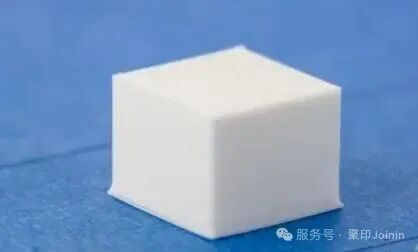
The key to precise hole drilling is the correct calibration of the 3D printer. There are various ways to calibrate, and here are four methods you should pay special attention to:
Steps per Millimeter:The steps per millimeter setting tells the 3D printer how much each motor should turn for every millimeter it moves. If these settings are incorrect, the holes generated by your printer will always be too large or too small. Fortunately, we have dedicated calibration guides to help you find the right steps per millimeter setting for your machine.
Axis Alignment:Axis orthogonality refers to how perpendicular the printer’s motion axes are to each other. If they are not perfectly vertical, the printer’s movements will deviate, resulting in slightly oval holes. To test orthogonality, use our recommended calibration cube with pegs. Based on this, physically adjust the printer’s axes until they are perfectly vertical.
First Layer Calibration:As you may have experienced, the first layer of 3D printing is crucial for successful results. Especially for holes, nailing the first layer is vital to avoid the “elephant foot,” which refers to the print being too close to the bed at the start. This can affect the size of the hole openings, leading to poor fitting later on.
Proper Clearance:Each machine has slightly different precision, so you cannot expect parts to always fit together perfectly. This is where clearance comes into play; these are small gaps in the design that ensure there is enough room for proper fitting.
Once you have completed these four steps, you can start designing! Here are five tips to help you successfully create 3D printed holes.
1
Don’t Start in Mid-Air
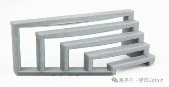
A series of short and long 3D printed bridges (Source: UltiMaker)
In appropriate cases, 3D printers can print bridges. Bridges (as shown above) can stretch plastic from one end of a gap to the other, reducing the chances of material hanging in the middle. However, if you drill holes in a bridge, it disrupts this delicate balance, preventing the plastic from passing straight through the gap; the edges of the hole—circular—must be extruded into the air with nothing to hold onto. This can lead to catastrophic chaos in unsupported print paths, either ruining your print or resulting in complete failure.
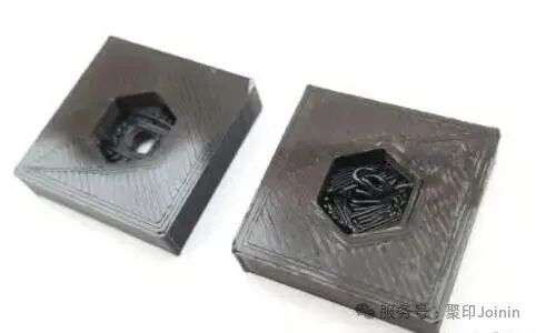
A modified air hole (left) and a failed, unmodified hole (right) (Source: Shop3D.ca)
There are typically two ways to solve this issue.
First, some users prefer to scatter hollow holes, placing them on a series of straight bridges. As shown in the image above, the edges of the hole can rest on a series of surrounding layers, preventing the aforementioned phenomenon of printing in thin air. The result is a neater, support-free product.
Alternatively, some users prefer to fill the holes with one or two layers of plastic, essentially sealing the bottom of the holes to create a flat bridge. Just adding this thin layer of plastic provides good support from below for the holes, which can later be cut away with an X-acto knife. From a design perspective, this is also easier to implement than the first option.
2
Beware of Shrinkage
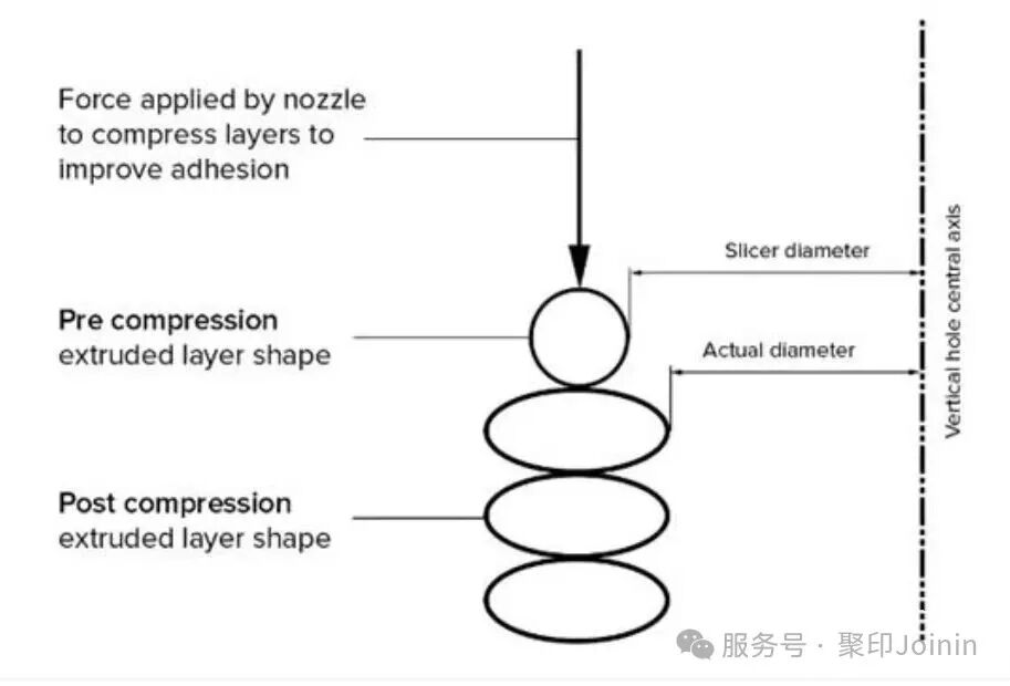
Visualization of compression in extrusion layers, leading to undersized holes (Source: Hubs)
Shrinkage is another important consideration for 3D printed holes. Although shrinkage can occur in various ways, the result is always the same: the holes will be slightly smaller than you expect. While this change is subtle, it is enough to distinguish between a bolt that fits too tightly and one that slides through directly.
Shrinkage has three main causes:
Material Shrinkage:Materials shrink after cooling. This is the culprit behind many notorious print failures, including warping and layer separation. For holes, this shrinkage can lead to parts being slightly undersized, preventing proper fitting.
Layer Compression:This can cause holes to shrink, but it is actually due to layers being too large. When the printer lays down a new layer, a compressive force is applied (as shown in the image above). While this increases the strength of the part, it can also cause the lower layers to be slightly compressed beyond their original boundaries. The result is that the printed parts are overly “bulged” in all directions, including inside the holes.
Mesh Resolution:While technically not a “shrinkage,” mesh resolution can indeed cause printed holes to be smaller than originally designed. The key here is that for most 3D print files, a “hole” is not actually a perfect circle but an approximation made up of polygons. The result is a slight cornering, leading to printed holes being smaller than initially designed.
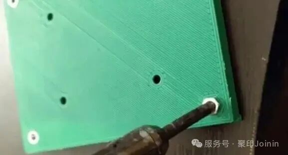
Manufacturers employ various techniques to address shrinkage issues (Source: hartk1213 via Reddit)
To address these issues, you can design the holes slightly larger to account for shrinkage. After printing, the holes will shrink down closer to the ideal size. It may take some trial and error to find the best position, but you will likely discover some margin for achieving the desired fit.
Additionally, you can try the material shrinkage settings in your slicer. While different tools may have different names, there is usually an option to specify filament shrinkage rates. Similar settings include “horizontal expansion,” which can also prevent shrinkage by automatically expanding or contracting the model before printing.
Finally, you can always choose to leave the holes as they are (or even slightly smaller than their original size). If you plan to tap threads, this will give you some space for screw engagement; otherwise, you can simply drill holes to the precise dimensions you require.
3
Avoid Overhangs
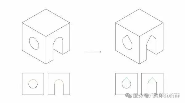
Teardrop shapes allow for overhang-free printing of horizontal holes (Source: flowalistik via Wikifactory)
So far, most of what we have discussed applies to vertical holes. What if you are dealing with horizontal holes? In this case, your biggest challenge may be the overhangs.
As shown in the image above, the overhangs formed by horizontal holes become steeper as the hole closes. During printing, this means the top of the hole is prone to sagging, causing the opening to become slightly “flattened.” If you want to insert a bolt, this is enough to block the opening.
Fortunately, this issue is easily resolved by using teardrop-shaped holes instead of perfectly round holes (as shown in the image above). This design avoids the overhang of the hole, allowing the print to maintain the desired curvature. While this technique may slightly increase the complexity of the 3D design, it is a small price to pay for achieving an accurate final product.
4
Add Fastening/Compliance Mechanisms
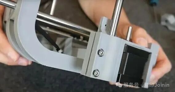
Inserting linear rods into slot holes and tightening to ensure a secure fit (Source: Maker’s Muse via YouTube)
In some cases, you may need a hole that tightly wraps around an object. This often occurs when installing bearings or rods into 3D printed parts. How do you balance ease of assembly with a secure installation?
In this case, your best option may be to design holes with a bit of clearance. This allows for easy insertion of components without sacrificing too much “grip” and stability. There are typically two designs for this:
Fastening Mechanisms:These mechanisms can make the original hole large enough to wear comfortably when tightened later. A common design approach is to add a slot along the length of each hole, as shown in the image above. Based on this, bolts can be used to close the gap and clamp the object.
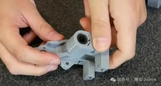
Bearings inserted with flexible hole mechanisms (Source: Maker’s Muse via YouTube)
Compliance Mechanisms:If alignment is an issue (such as with linear bearings), compliance mechanisms may be more suitable for your application. These mechanisms rely on the natural elasticity of plastic to provide some clearance in the hole dimensions, allowing for a tight friction fit. You can see this in the operation above; the elasticity of the plastic provides enough space for the bearings.
5
Adjust with Tools
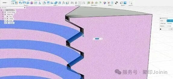
Using push-pull tools to improve the fit of threaded holes (Source: Hironori Kondo via All3DP)
So far, we have mainly focused on bare, clean holes, but this does not cover everything. Sometimes, you may need threaded holes. These holes can be directly screwed with bolts without needing separate tapping or nuts. While this is convenient, it can also negate many of the previous tips. For example, it is difficult to prevent shrinkage since bolt threads have standard sizes.
To address this issue, we need to creatively adjust the design of the holes. A good method is to use push/pull tools to widen the gap between the bolt and the threaded hole, effectively increasing the clearance. You can combine this with the shrinkage settings mentioned above to adjust the fit.
When designing, keep in mind that larger threads will come out neater, especially on FDM 3D printers. We recommend using a lower layer height for printing to create more precise threads.
If you are interested in 3D printing or have any questions or suggestions, feel free to follow us and reach out at any time.