This article provides a detailed introduction to the M5Stack Audio Expansion Module, covering product features, specifications, operation instructions, register descriptions, and the implementation of drivers in the XiaoZhi project based on M5Stack core.
1、Product Introduction
(1) Product Features
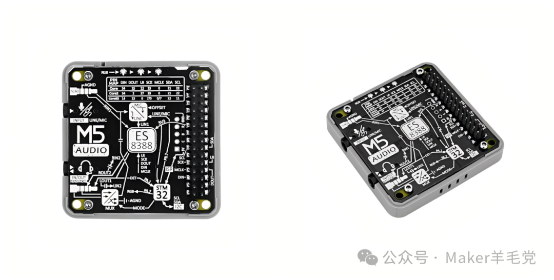
Module Audio is the audio expansion module for M5Stack, based on the ES8388 audio codec solution, equipped with an STM32G030F6P6 microcontroller, aimed at audio interaction. It features dual 3.5mm jacks (TRS for microphone input only, TRRS for input and output), supports switching between CTIA/OMTP headphone standards, and includes 3 WS2812C RGB lights. It is suitable for smart voice scenarios, with a working current of 23.53mA and a standby current of 8.58mA. Various function controls can be achieved through register configuration using the I2C protocol, meeting the needs for microphone recording and stereo audio playback.
1.Control Chip: Uses STM32G030F6P6 MCU, with I2C address 0x33.
2.Audio Function: Features high-fidelity audio codec, providing dual microphone inputs and 1 stereo headphone output.
3.Interface Type: Has TRS and TRRS dual 3.5mm jacks, where TRS is for microphone input only, and TRRS can achieve both microphone input and stereo playback. It also supports switching between CTIA (US standard) and OMTP (China standard) interfaces.
4.Indicator Lights: Includes 3 WS2812C RGB indicator lights.
(2) Specifications
|
Specification |
Parameter |
|
Audio Codec |
ES8388, I2C address 0x10 |
|
Jack Type |
1 TRS (microphone only), 1 TRRS (microphone/speaker combo jack) |
|
Working Current |
|
|
Standby Current |
|
|
Operating Temperature |
0 ~ 40 °C |
|
Product Size |
54.0 x 54.0 x 13.1mm |
|
Product Weight |
12.8g |
|
Packaging Size |
132.0 x 95.0 x 16.0mm |
|
Gross Weight |
26.3g |
(3) Operation Instructions
1.Plug Type and Standards: TRS is used for mono microphone input or stereo output (this product is for microphone input only); TRRS can achieve both microphone input and stereo playback. TRRS has two wiring standards: CTIA (US standard) and OMTP (China standard).
2.Pin Mapping: The board reserves two sets of corresponding I2S pins A/B for switching I2S signals with the default pin mapping of the host.
(4) Register Description
|
Register Address |
Register Name |
Read/Write Attribute |
Function Description |
Default Value |
|
0x00 |
Microphone Config |
Read/Write |
Configure LINE/MIC switch, 0 to turn off, 1 to turn on |
1 |
|
0x10 |
Headphone Mode |
Read/Write |
Select headphone mode, 0 for national standard, 1 for American standard |
0 |
|
0x20 |
Headphone Insert Status |
Read |
Detect headphone insertion status, 0 not inserted, 1 inserted |
– |
|
0x30 |
RGB Brightness |
Read/Write |
Set RGB light brightness, range 0 – 100 |
10 |
|
0x40 |
RGB LED |
Read/Write |
Set RGB light color, range 0 – 255 |
0 |
|
0xF0 |
Save Configuration to Flash |
Write |
Write 1 to save the current configuration to internal Flash |
– |
|
0xF0 |
Firmware Version |
Read |
Get software version number |
– |
|
0xF0 |
I2C Address |
Read/Write |
Configure I2C address, range 0x08 – 0x77 |
0x33 |
2、Driver Implementation of ES8388 Audio Codec in XiaoZhi Project
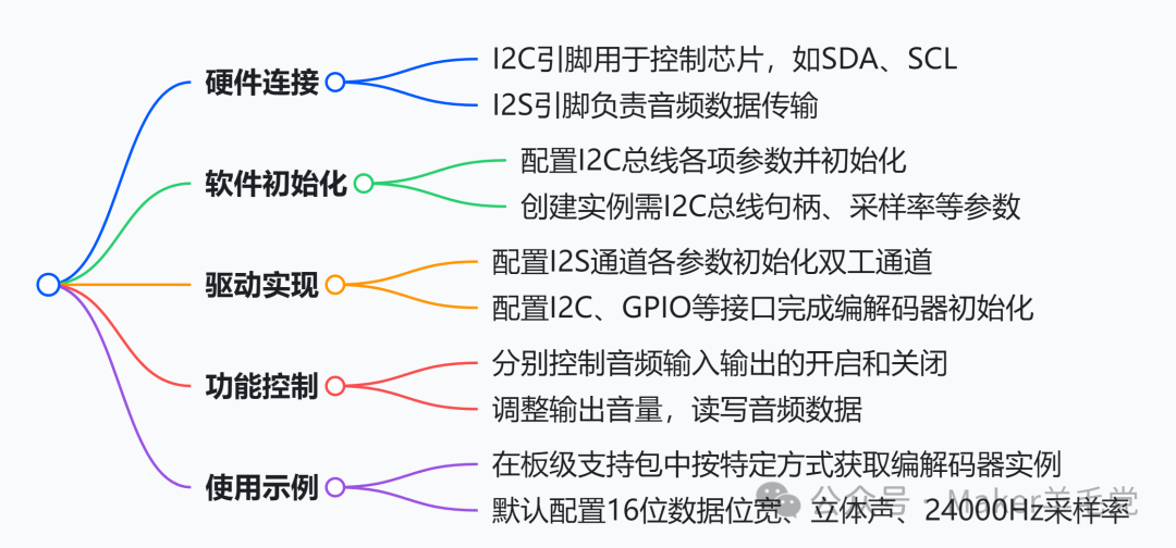
ES8388 is a high-quality audio codec controlled via I2C and data transmitted via I2S. In the XiaoZhi ESP32 project, its driver is encapsulated in the Es8388AudioCodec class. The driver steps include hardware connection (I2C and I2S pin connections), software initialization (initializing the I2C bus, creating codec instances), driver implementation (initializing I2S duplex channels, initializing the codec), and function control (enabling audio input/output, setting volume, reading/writing audio data). An example of usage is provided, with the default configuration set to 16-bit audio data width, stereo mode, and a sampling rate of 24000Hz. The PA_PIN in the example is not connected and may need adjustment in practice.
ES8388 is a high-quality audio codec controlled via I2C and data transmitted via I2S. In the XiaoZhi ESP32 project, its driver has been encapsulated in the Es8388AudioCodec class. The following are the specific steps to drive ES8388, which run normally on the atk_dnesp32s3 board:
1.Hardware Connection: ES8388 needs to connect to I2C pins (for control chips, such as SDA, SCL, defined in config.h lines 17 – 19) and I2S pins (for audio data transmission, defined in config.h lines 11 – 15).
2.Software Initialization
◦Initialize I2C Bus: Configure i2c_master_bus_config_t structure, including I2C port, SDA and SCL pins, clock source, etc., then use i2c_new_master_bus function to initialize the I2C bus, with code located in atk_dnesp32s3.cc lines 58 – 71.
◦Create ES8388 Audio Codec Instance: When creating an instance, provide I2C bus handle, I2C port number, input/output sampling rate, I2S pin configuration, etc., with code located in atk_dnesp32s3.cc lines 165 – 178.
3.ES8388 Driver Implementation
◦Initialize I2S Duplex Channel: Configure i2s_chan_config_t and i2s_std_config_t structures, setting basic properties, clock, data slots, and GPIO pin parameters for the I2S channel, then use i2s_new_channel and i2s_channel_init_std_mode functions to initialize the I2S duplex channel, with code located in es8388_audio_codec.cc lines 82 – 132.
◦Initialize ES8388 Codec: Completed in the constructor, including initializing data interface, control interface, GPIO interface, configuring ES8388 working mode, master mode, power amplifier pin parameters, and finally creating input/output devices, with code located in es8388_audio_codec.cc lines 7 – 67.
4.Function Control
◦Enable Audio Output: Controlled by EnableOutput function, when enabled, set audio parameters and open output device, set output volume, and when closed, turn off output device, with code located in es8388_audio_codec.cc lines 159 – 191.
◦Enable Audio Input: Controlled by EnableInput function, when enabled, set audio parameters and open input device, set input gain, and when closed, turn off input device, with code located in es8388_audio_codec.cc lines 139 – 157.
◦Set Output Volume: Use SetOutputVolume function to set output volume, with code located in es8388_audio_codec.cc lines 134 – 137.
◦Audio Data Read/Write: Read function is used to read audio data, Write function is used to write audio data, with code located in es8388_audio_codec.cc lines 193 – 205.
5.Usage Example: In the board support package, obtain the ES8388 audio codec instance by overriding GetAudioCodec function, with code located in atk_dnesp32s3.cc lines 164 – 179.
3. Porting XiaoZhi Based on M5Stack Core
Reference for config.h file settings:
#ifndef _BOARD_CONFIG_H_#define _BOARD_CONFIG_H_#include <driver/gpio.h>#define AUDIO_INPUT_SAMPLE_RATE 24000#define AUDIO_OUTPUT_SAMPLE_RATE 24000#define AUDIO_I2S_GPIO_MCLK GPIO_NUM_0#define AUDIO_I2S_GPIO_WS GPIO_NUM_12#define AUDIO_I2S_GPIO_BCLK GPIO_NUM_13#define AUDIO_I2S_GPIO_DIN GPIO_NUM_34#define AUDIO_I2S_GPIO_DOUT GPIO_NUM_15#define AUDIO_CODEC_I2C_PORT (I2C_NUM_1)#define AUDIO_CODEC_I2C_SDA_PIN GPIO_NUM_21#define AUDIO_CODEC_I2C_SCL_PIN GPIO_NUM_22#define AUDIO_CODEC_ES8388_ADDR ES8388_CODEC_DEFAULT_ADDR#define M5MODULE_AUDIO_ADDR 0x33// #define AUDIO_CODEC_ES8388_ADDR 0x10#define BUILTIN_LED_GPIO GPIO_NUM_NC#define BOOT_BUTTON_GPIO GPIO_NUM_38#define TOUCH_BUTTON_GPIO GPIO_NUM_NC#define VOLUME_UP_BUTTON_GPIO GPIO_NUM_37#define VOLUME_DOWN_BUTTON_GPIO GPIO_NUM_39#define BUILTIN_LED_GPIO GPIO_NUM_NC#define DISPLAY_CS_PIN GPIO_NUM_14#define DISPLAY_BACKLIGHT_PIN GPIO_NUM_32#define DISPLAY_MOSI_PIN GPIO_NUM_23#define DISPLAY_CLK_PIN GPIO_NUM_18#define DISPLAY_DC_PIN GPIO_NUM_27#define DISPLAY_RST_PIN GPIO_NUM_33#define DISPLAY_WIDTH 320#define DISPLAY_HEIGHT 240#define DISPLAY_MIRROR_X false#define DISPLAY_MIRROR_Y false#define DISPLAY_SWAP_XY false#define DISPLAY_OFFSET_X 0#define DISPLAY_OFFSET_Y 0#define DISPLAY_BACKLIGHT_OUTPUT_INVERT true#endif // _BOARD_CONFIG_H_Porting XiaoZhi based on M5Stack core, core2, and core3 can refer to the audio decoding section.
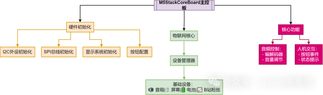
#include "wifi_board.h"#include "es8388_audio_codec.h"#include "display/lcd_display.h"#include "system_reset.h"#include "application.h"#include "button.h"#include "config.h"#include "iot/thing_manager.h"#include "led/single_led.h"#include "assets/lang_config.h"#include "i2c_device.h"#include <wifi_station.h>#include <esp_log.h>#include <driver/i2c_master.h>#include <esp_lcd_panel_ops.h>#include <esp_lcd_panel_vendor.h>#include <esp_lcd_ili9341.h>#include <esp_timer.h>// #include "m5ModuleAudio_ledthings.h"// #include "M5ModuleAudio.h"#define TAG "M5StackCoreBoard"LV_FONT_DECLARE(font_puhui_20_4);LV_FONT_DECLARE(font_awesome_20_4);typedef enum{ AUDIO_HPMODE_NATIONAL = 0, AUDIO_HPMODE_AMERICAN} audio_hpmode_t;class M5ModuleAudio : public I2cDevice{public: M5ModuleAudio(i2c_master_bus_handle_t i2c_bus, uint8_t addr) : I2cDevice(i2c_bus, addr) {} void setRGBBrightness(uint8_t brightness) { if (brightness > 100) brightness = 100; WriteReg(0x30, brightness); } void setHPMode(audio_hpmode_t mode) { WriteReg(0x10, mode); } void setRGBLED(uint8_t num, uint32_t color) { if (num > 2) num = 2; // Convert color value to RGB format uint8_t red = (color & 0xFF); // Extract Red component uint8_t green = (color & 0xFF00) >> 8; // Extract Green component uint8_t blue = (color >> 16) & 0xFF; // Extract Blue component // Calculate register address uint8_t regBase = 0x40 + num * 3; // Use WriteReg method to write R, G, B data separately WriteReg(regBase, red); // Write Red data WriteReg(regBase + 1, green); // Write Green data WriteReg(regBase + 2, blue); // Write Blue data }};class M5StackCoreBoard : public WifiBoard{private: i2c_master_bus_handle_t i2c_bus_; LcdDisplay *display_; M5ModuleAudio *audio_module_; esp_timer_handle_t touchpad_timer_; Button boot_button_; // Button touch_button_; Button volume_up_button_; Button volume_down_button_; void InitializeI2c() { // Initialize I2C peripheral i2c_master_bus_config_t i2c_bus_cfg = { .i2c_port = AUDIO_CODEC_I2C_PORT, .sda_io_num = AUDIO_CODEC_I2C_SDA_PIN, .scl_io_num = AUDIO_CODEC_I2C_SCL_PIN, .clk_source = I2C_CLK_SRC_DEFAULT, .glitch_ignore_cnt = 7, .intr_priority = 0, .trans_queue_depth = 0, .flags = { .enable_internal_pullup = 1, }, }; ESP_ERROR_CHECK(i2c_new_master_bus(&i2c_bus_cfg, &i2c_bus_)); } void I2cDetect() { uint8_t address; printf(" 0 1 2 3 4 5 6 7 8 9 a b c d e f\r\n"); for (int i = 0; i < 128; i += 16) { printf("%02x: ", i); for (int j = 0; j < 16; j++) { fflush(stdout); address = i + j; esp_err_t ret = i2c_master_probe(i2c_bus_, address, pdMS_TO_TICKS(200)); if (ret == ESP_OK) { printf("%02x ", address); } else if (ret == ESP_ERR_TIMEOUT) { printf("UU "); } else { printf("-- "); } } printf("\r\n"); } } void InitializeSpi() { spi_bus_config_t buscfg = {}; buscfg.mosi_io_num = DISPLAY_MOSI_PIN; buscfg.miso_io_num = GPIO_NUM_NC; buscfg.sclk_io_num = DISPLAY_CLK_PIN; buscfg.quadwp_io_num = GPIO_NUM_NC; buscfg.quadhd_io_num = GPIO_NUM_NC; buscfg.max_transfer_sz = DISPLAY_WIDTH * DISPLAY_HEIGHT * sizeof(uint16_t); ESP_ERROR_CHECK(spi_bus_initialize(SPI3_HOST, &buscfg, SPI_DMA_CH_AUTO)); } void InitializeIli9342Display() { ESP_LOGI(TAG, "Init IlI9342"); esp_lcd_panel_io_handle_t panel_io = nullptr; esp_lcd_panel_handle_t panel = nullptr; ESP_LOGD(TAG, "Install panel IO"); esp_lcd_panel_io_spi_config_t io_config = {}; io_config.cs_gpio_num = DISPLAY_CS_PIN; io_config.dc_gpio_num = DISPLAY_DC_PIN; io_config.spi_mode = 2; io_config.pclk_hz = 40 * 1000 * 1000; io_config.trans_queue_depth = 10; io_config.lcd_cmd_bits = 8; io_config.lcd_param_bits = 8; ESP_ERROR_CHECK(esp_lcd_new_panel_io_spi(SPI3_HOST, &io_config, &panel_io)); ESP_LOGD(TAG, "Install LCD driver"); esp_lcd_panel_dev_config_t panel_config = {}; panel_config.reset_gpio_num = DISPLAY_RST_PIN; panel_config.rgb_ele_order = LCD_RGB_ELEMENT_ORDER_BGR; panel_config.bits_per_pixel = 16; ESP_ERROR_CHECK(esp_lcd_new_panel_ili9341(panel_io, &panel_config, &panel)); esp_lcd_panel_reset(panel); esp_lcd_panel_init(panel); esp_lcd_panel_invert_color(panel, true); esp_lcd_panel_swap_xy(panel, DISPLAY_SWAP_XY); esp_lcd_panel_mirror(panel, DISPLAY_MIRROR_X, DISPLAY_MIRROR_Y); display_ = new SpiLcdDisplay(panel_io, panel, DISPLAY_WIDTH, DISPLAY_HEIGHT, DISPLAY_OFFSET_X, DISPLAY_OFFSET_Y, DISPLAY_MIRROR_X, DISPLAY_MIRROR_Y, DISPLAY_SWAP_XY, { .text_font = &font_puhui_20_4, .icon_font = &font_awesome_20_4,#if CONFIG_USE_WECHAT_MESSAGE_STYLE .emoji_font = font_emoji_32_init(),#else .emoji_font = font_emoji_64_init(),#endif }); } void InitializeButtons() { boot_button_.OnClick([this]() { auto& app = Application::GetInstance(); if (app.GetDeviceState() == kDeviceStateStarting && !WifiStation::GetInstance().IsConnected()) { ResetWifiConfiguration(); } app.ToggleChatState(); }); boot_button_.OnPressDown([this]() { Application::GetInstance().StartListening(); }); boot_button_.OnPressUp([this]() { Application::GetInstance().StopListening(); }); volume_up_button_.OnClick([this]() { auto codec = GetAudioCodec(); auto volume = codec->output_volume() + 10; if (volume > 100) { volume = 100; } codec->SetOutputVolume(volume); GetDisplay()->ShowNotification(Lang::Strings::VOLUME + std::to_string(volume)); }); volume_up_button_.OnLongPress([this]() { GetAudioCodec()->SetOutputVolume(100); GetDisplay()->ShowNotification(Lang::Strings::MAX_VOLUME); }); volume_down_button_.OnClick([this]() { auto codec = GetAudioCodec(); auto volume = codec->output_volume() - 10; if (volume < 0) { volume = 0; } codec->SetOutputVolume(volume); GetDisplay()->ShowNotification(Lang::Strings::VOLUME + std::to_string(volume)); }); volume_down_button_.OnLongPress([this]() { GetAudioCodec()->SetOutputVolume(0); GetDisplay()->ShowNotification(Lang::Strings::MUTED); }); } // IoT initialization, adding AI-visible devices void InitializeIot() { auto &thing_manager = iot::ThingManager::GetInstance(); thing_manager.AddThing(iot::CreateThing("Speaker")); thing_manager.AddThing(iot::CreateThing("Screen")); thing_manager.AddThing(iot::CreateThing("Battery")); thing_manager.AddThing(iot::CreateThing("BilibiliFans")); // audio_module_ = new M5ModuleAudio(i2c_bus_,M5MODULE_AUDIO_ADDR); // Add M5AudioLED Thing to ThingManager // thing_manager.AddThing(new M5AudioLED(audio_module_)); // thing_manager.AddThing(iot::CreateThing("M5AudioLed")); }public: M5StackCoreBoard() : boot_button_(BOOT_BUTTON_GPIO), volume_up_button_(VOLUME_UP_BUTTON_GPIO), volume_down_button_(VOLUME_DOWN_BUTTON_GPIO) { InitializeI2c(); I2cDetect(); InitializeButtons(); InitializeSpi(); InitializeIli9342Display(); InitializeIot(); GetBacklight()->RestoreBrightness(); } virtual AudioCodec *GetAudioCodec() override { static Es8388AudioCodec audio_codec( i2c_bus_, AUDIO_CODEC_I2C_PORT, AUDIO_INPUT_SAMPLE_RATE, AUDIO_OUTPUT_SAMPLE_RATE, AUDIO_I2S_GPIO_MCLK, AUDIO_I2S_GPIO_BCLK, AUDIO_I2S_GPIO_WS, AUDIO_I2S_GPIO_DOUT, AUDIO_I2S_GPIO_DIN, GPIO_NUM_NC, AUDIO_CODEC_ES8388_ADDR); return &audio_codec; } virtual Display *GetDisplay() override { return display_; } virtual Backlight *GetBacklight() override { static PwmBacklight backlight(DISPLAY_BACKLIGHT_PIN, DISPLAY_BACKLIGHT_OUTPUT_INVERT); return &backlight; }};DECLARE_BOARD(M5StackCoreBoard);Comments:
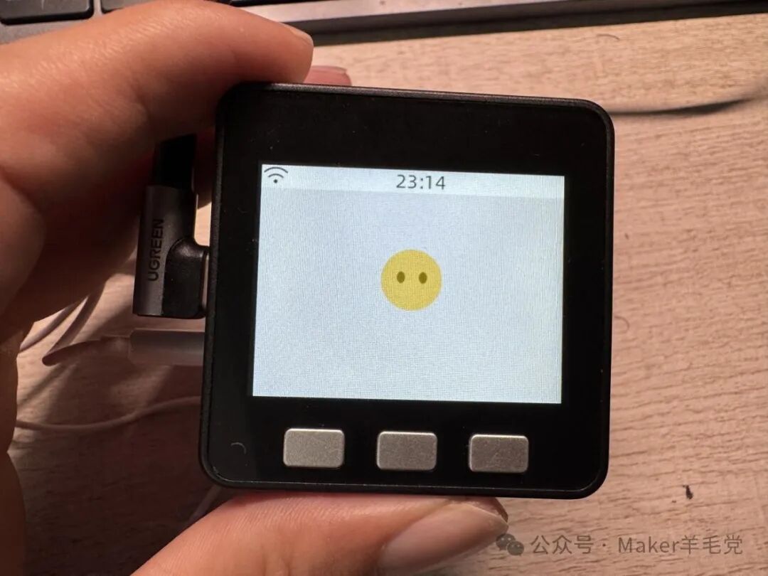
This M5Stack audio expansion module integrates speaker and microphone functions, providing a complete solution for creating high-quality audio players. In the XiaoZhi project, M5Stack core and core2, which were originally unable to participate in the project, gained the opportunity to realize XiaoZhi functions through this module. Users can enjoy a high-quality XiaoZhi experience with minimal investment. In practical use, this module is very convenient when paired with mobile phone headphones, especially suitable for private communication scenarios, avoiding disturbance to others. If external speakers are needed, just configure a microphone with a headphone jack.