Today, we will discuss interrupt handling in ARM Cortex-M. In embedded systems, interrupts are the core mechanism for achieving real-time responses. Imagine if there were no interrupts:
- • When a button is pressed, the system might be busy with other tasks and miss the response.
- • Incoming communication data might be lost due to untimely processing.
- • Timed tasks would be difficult to execute accurately, leading to chaotic system timing. Interrupts act like a “VIP lane” in the microcontroller world, allowing important events to be processed immediately without waiting in line.
Cortex-M Interrupt System Architecture
The interrupt system of the ARM Cortex-M series is one of its most powerful features, far more advanced than traditional 8-bit and 16-bit microcontrollers. At its core is the NVIC (Nested Vectored Interrupt Controller).
Key Point: Unlike traditional microcontrollers like the 8051, the Cortex-M interrupt system implements vector jumps and state saving entirely in hardware, greatly improving interrupt response speed.
A diagram to understand the position of NVIC in the system:
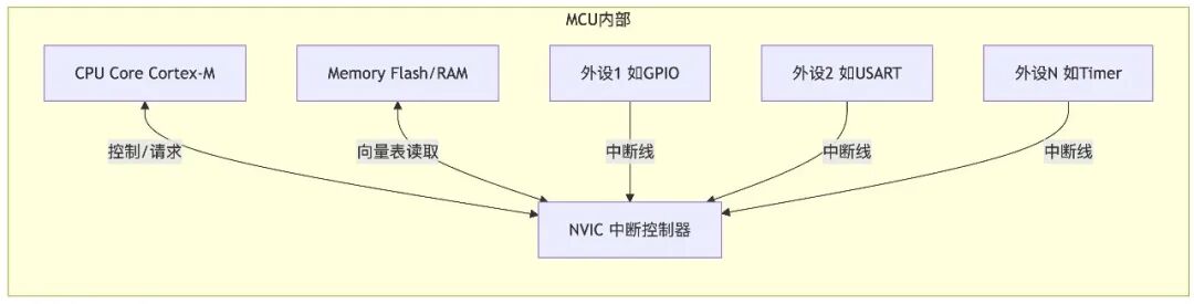
Powerful Features of NVIC:
- • Fast Interrupt Response: From interrupt trigger to ISR execution takes only 12-20 CPU clock cycles.
- • Support for Interrupt Nesting: High-priority interrupts can interrupt low-priority interrupts.
- • Dynamic Priority Adjustment: Software can modify interrupt priorities at runtime.
- • Pending Interrupt Management: Software can trigger or cancel pending interrupts.
- • Vectorized Interrupt Handling: Each interrupt source corresponds to a unique interrupt service function.
Detailed Explanation of the Interrupt Vector Table
When the MCU powers on, aside from setting the stack pointer (MSP), the most important task is to locate the interrupt vector table. This table acts like a map, telling the CPU where to find the corresponding handler (ISR – Interrupt Service Routine) when a specific interrupt or exception occurs.
__attribute__((section(".isr_vector"))) // Ensure placed in the specified section
void (* const g_pfnVectors[])(void) = {
    (void *)&_estack,           // 0. Stack top address (initial value of MSP)
    Reset_Handler,              // 1. Reset interrupt handler
    NMI_Handler,                // 2. NMI (Non-Maskable Interrupt)
    HardFault_Handler,          // 3. Hard Fault (very important!)
    MemManage_Handler,          // 4. Memory Management Fault
    BusFault_Handler,           // 5. Bus Fault
    UsageFault_Handler,         // 6. Usage Fault
    0, 0, 0, 0,                 // 7-10. Reserved
    SVC_Handler,                // 11. System Service Call (commonly used in RTOS)
    DebugMon_Handler,           // 12. Debug Monitor
    0,                          // 13. Reserved
    PendSV_Handler,             // 14. Pendable System Call (critical for RTOS context switching!)
    SysTick_Handler,            // 15. SysTick Timer (RTOS heartbeat, delay basis)
    // --- External interrupts (IRQ) start here ---
    WWDG_IRQHandler,            // 16. Window Watchdog Interrupt
    PVD_IRQHandler,             // 17. Power Voltage Detector Interrupt
    // ... More peripheral interrupts based on specific MCU models
};
Pitfall Record: I once encountered a strange issue where the program behaved abnormally after a certain peripheral interrupt. After much investigation, I found that the ISR pointer for that peripheral in the vector table had been accidentally changed to NULL! Therefore, always check if your vector table is correct and complete! Especially after using a Bootloader or modifying the startup file. Also, remember that the vector table address can be relocated via the
<span>VTOR</span>register, so understanding where it is located is crucial!
Interrupt Priority System
Interrupts are not first-come, first-served; they are prioritized by “levels”! NVIC has a precise priority system that determines which interrupt can “cut in line” and which must “wait in line”.
Core Concepts:
- 1. Preemption Priority: Determines whether an interrupt can interrupt another currently executing interrupt. Higher levels can interrupt lower levels.
- 2. Sub-priority: When two interrupts have the same preemption priority, the one with the higher sub-priority executes first.
(Note: If one interrupt is already executing, another interrupt with the same preemption priority cannot interrupt the currently executing interrupt. Sub-priority only takes effect when multiple interrupts with the same preemption priority are pending, determining which one should be responded to next after the current ISR ends (the one with the smaller sub-priority value is prioritized)).
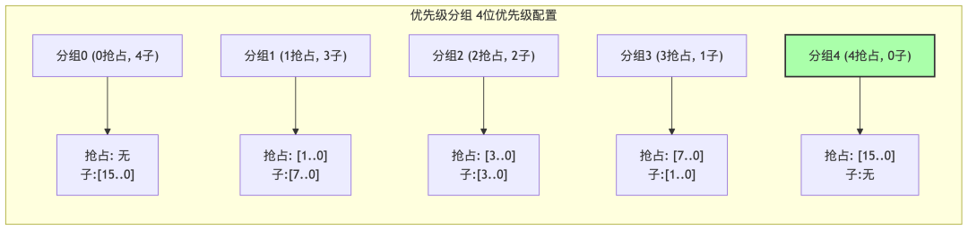
Key Configuration: Priority Grouping
This determines how many bits are used for preemption priority and how many bits are used for sub-priority. It is set using the <span>NVIC_SetPriorityGrouping()</span> function, and the entire system is usually set only once!
A diagram to understand priority grouping (using a common 4-bit priority as an example):
How to Set Priorities?
⚠ High Energy Warning! Must-read for beginners! In Cortex-M, the smaller the priority value, the higher the actual priority! For example, priority 0 > priority 1 > priority 15. Don’t get it mixed up!
// 1. Set priority grouping (usually during system initialization)
NVIC_SetPriorityGrouping(NVIC_PRIORITYGROUP_4); // For example: all used for preemption priority

// 2. Set specific interrupt priorities
// NVIC_EncodePriority(priority grouping, preemption priority, sub-priority)
// Note: Here, the smaller the value, the higher the priority!
NVIC_SetPriority(USART1_IRQn, NVIC_EncodePriority(NVIC_GetPriorityGrouping(), 1, 0)); // Set USART1 priority to 1
NVIC_SetPriority(TIM2_IRQn,   NVIC_EncodePriority(NVIC_GetPriorityGrouping(), 5, 0)); // Set TIM2 priority to 5 (lower than USART1)
Differences in Priority Bit Count:
- • Cortex-M0/M0+: Typically only 2 bits (4 levels) or fewer.
- • Cortex-M3/M4/M7/M33, etc.: Support more bits (e.g., 3-8 bits), but the specific implementation of how many bits is determined by the chip manufacturer, commonly 4 bits (16 levels).
Interrupt Latency and Queue Mechanism
When multiple interrupts are triggered simultaneously or a new interrupt is triggered while processing one, how does NVIC handle it? When an interrupt occurs, the CPU cannot respond instantly; there will be a slight delay. This delay mainly includes:
- 1. Hardware Recognition Delay: The peripheral signal reaching the NVIC. (very short)
- 2. Synchronization Delay: Waiting for the current instruction to complete. Additionally, the wait states when fetching instructions from Flash will also increase the delay.
- 3. NVIC Processing: Determining priority and preparing to jump.
- 4. Context Saving: The hardware automatically pushes registers R0-R3, R12, LR, PC, xPSR onto the stack. (about 12 cycles)
Optimization Tip: If extremely high interrupt latency is required, critical code can be executed in RAM to avoid the impact of Flash wait states.
The total delay is usually around 12-20 clock cycles, which is already very fast!
NVIC’s “Black Technology”: Reducing Latency
- • Tail-Chaining: If an ISR has just finished executing and another interrupt is pending (and priority allows execution), NVIC will skip the push/pop process and jump directly to the next ISR, reducing the delay to about 6 cycles! Extremely efficient!
- • Late Arrival: If a high-priority interrupt arrives while a low-priority interrupt is being pushed onto the stack, NVIC will allow the high-priority one to execute first, then return to execute the low-priority one.
Summary of Queue Rules:
- 1. Preemption is King: High preemption priority interrupts > low preemption priority interrupts.
- 2. Same Level Looks at Sub: If preemption priorities are the same, the one with the higher sub-priority responds first (but cannot interrupt the currently executing same-level interrupt).
- 3. Completely Identical Looks at Number: If both preemption and sub-priority are the same, the interrupt with the smaller number responds first.
Writing Interrupt Service Functions
Writing a good ISR (Interrupt Service Routine) is an art that directly affects system stability and real-time performance. Please remember the following golden rules:
- • Short and Fast: ISRs should be as short and efficient as possible, doing only the most core and urgent tasks.
- • Non-blocking: Never use
<span>HAL_Delay()</span>, wait for flags, or any time-consuming operations in an ISR. - • Set Flags, Main Processing: Quickly handle hardware in the ISR (e.g., read data, clear flags), then set a global flag to let the main loop or RTOS task handle complex follow-up processing.
- • Protect Shared Resources: If the ISR accesses global variables/peripherals used by the main program or other interrupts, critical section protection (disabling interrupts/semaphores, etc.) must be added; otherwise, data will become corrupted!
- • Clear Interrupt Flags: After processing the interrupt source, be sure to clear the corresponding interrupt flag; otherwise, the ISR will keep re-entering until the system crashes!
ISR Handling Function (Example of Serial Reception):
volatile uint8_t g_uartRxData;
volatile uint8_t g_uartRxFlag = 0;

void USART1_IRQHandler(void)
{
    // 1. Check the interrupt source (Is it a receive interrupt?)
    if (LL_USART_IsActiveFlag_RXNE(USART1) && LL_USART_IsEnabledIT_RXNE(USART1))
    {
        // 2. Handle hardware & clear flag (core!)
        g_uartRxData = LL_USART_ReceiveData8(USART1);
        // Important: Be sure to consult the MCU reference manual to confirm how to clear the RXNE flag!
        // Some peripherals automatically clear it after reading the data register, but explicit clearing (if required by the manual) or at least knowing the clearing mechanism is safer.
        // LL_USART_ClearFlag_RXNE(USART1); // Confirm if manual clearing is needed

        // 3. Set flag to notify the main program
        g_uartRxFlag = 1;

        // 4. (Optional) If using RTOS, may need to signal a semaphore/message queue here and trigger task switching
        // BaseType_t xHigherPriorityTaskWoken = pdFALSE;
        // xQueueSendFromISR(g_uartRxQueue, &g_uartRxData, &xHigherPriorityTaskWoken);
        // portYIELD_FROM_ISR(xHigherPriorityTaskWoken);
    }

    // (There may be other interrupt sources, such as transmission complete, errors, etc., that need to be handled as well)
    if (LL_USART_IsActiveFlag_TC(USART1) && LL_USART_IsEnabledIT_TC(USART1))
    {
        LL_USART_ClearFlag_TC(USART1); // Clear transmission complete flag
        // ... Handle transmission complete logic ...
    }
}

// Main loop checks the flag
int main(void)
{
    // ... Initialization ...
    while (1)
    {
        if (g_uartRxFlag)
        {
            g_uartRxFlag = 0; // Clear flag
            // Process received data g_uartRxData here
            process_received_data(g_uartRxData);
        }
        // ... Other main loop tasks ...
    }
}
Common Traps in Interrupt Programming
1. Forgetting to Clear Interrupt Flags!
// Incorrect Example (Timer Interrupt)
void TIM2_IRQHandler(void) {
    // Handled counting, but forgot to clear the flag!
    timer_counter++;
}

// Correct Approach
void TIM2_IRQHandler(void) {
    if (LL_TIM_IsActiveFlag_UPDATE(TIM2)) { // Check if it's an update interrupt
        LL_TIM_ClearFlag_UPDATE(TIM2);     // Clear the flag first! Good habit!
        timer_counter++;
    }
}
2. Executing Time-Consuming Operations in ISR!
// Incorrect Example (Writing Flash upon Serial Data Reception)
void USART1_IRQHandler(void) {
    if(LL_USART_IsActiveFlag_RXNE(USART1)) {
        uint8_t data = LL_USART_ReceiveData8(USART1);
        // Flash operations are very time-consuming and will block everything!
        Flash_ErasePage(ADDRESS);
        Flash_ProgramWord(ADDRESS, data);
    }
}

// Correct Approach
volatile uint8_t g_dataToFlash;
volatile uint8_t g_flashWriteRequest = 0;
void USART1_IRQHandler(void) {
    if(LL_USART_IsActiveFlag_RXNE(USART1)) {
        g_dataToFlash = LL_USART_ReceiveData8(USART1);
        g_flashWriteRequest = 1; // Set request flag
    }
}
// Handle Flash writing in the main loop or task
// if (g_flashWriteRequest) { ... }
3. Not Protecting Shared Resources! (Data Corruption)
// Incorrect Example (Simple Circular Buffer)
uint8_t buffer[100];
uint8_t write_idx = 0;
void USART1_IRQHandler(void) {
    // Assume the main program is also reading/writing write_idx
    buffer[write_idx++] = LL_USART_ReceiveData8(USART1); // Non-atomic operation, may be interrupted
    if (write_idx >= 100) write_idx = 0;
}

// Correct Approach (Using Global Interrupt Protection)
volatile uint8_t buffer[100];
volatile uint8_t write_idx = 0;
void USART1_IRQHandler(void) {
    uint32_t primask_status;
    primask_status = __get_PRIMASK(); // Save current interrupt status
    __disable_irq(); // Disable global interrupts, enter critical section

    // --- Critical section code ---
    buffer[write_idx++] = LL_USART_ReceiveData8(USART1);
    if (write_idx >= 100) write_idx = 0;
    // --- End of critical section ---

    if (!primask_status) { // If it was originally enabled, restore
        __enable_irq(); // Enable global interrupts
    }
}
// Note: The main program must also protect write_idx using the same method!
// In RTOS, there are more elegant protection methods (like BASEPRI or using semaphores/mutexes)
Note: <span>__disable_irq()</span><span> will mask all interrupts, which may increase the response latency of other high-priority interrupts in the system. For Cortex-M cores that support the </span><code><span>BASEPRI</span> register (like M3/M4/M7), in RTOS environments or when fine control of interrupt masking is needed, it is more recommended to use the method of modifying the <span>BASEPRI</span> register to only mask interrupts below or equal to a specific priority (like the highest priority for RTOS system calls). Alternatively, using RTOS-provided mutexes or semaphores to protect shared resources is a more robust and recommended approach.
Advanced Interrupt Techniques
When using real-time operating systems like FreeRTOS or RT-Thread, interrupt handling requires more strategic considerations.
1. Use RTOS-provided ISR-safe APIs
Many RTOS APIs (like queue sending, semaphore releasing) have dedicated ISR versions (usually suffixed with <span>FromISR</span>). These versions must be used! Because they handle context switching and critical section protection internally.
// FreeRTOS Example: Sending data to a queue in ISR
void USART1_IRQHandler(void) {
    uint8_t data = LL_USART_ReceiveData8(USART1);
    BaseType_t xHigherPriorityTaskWoken = pdFALSE; // Used to determine if a task switch is needed

    // Use xQueueSendFromISR instead of xQueueSend
    xQueueSendFromISR(g_uartRxQueue, &data, &xHigherPriorityTaskWoken);

    // If the send operation woke a higher priority task, manually trigger a scheduling
    portYIELD_FROM_ISR(xHigherPriorityTaskWoken);
}
2. Software Triggered Interrupts (PendSV / SVC)
- • PendSV: This is the “designated” interrupt for context switching in RTOS. It has the lowest priority and can be interrupted by other interrupts, ensuring that switching occurs at a safe moment. It is usually suspended by the RTOS kernel when a switch is needed (like when a delay ends or a task is awakened) via
<span>SCB->ICSR |= SCB_ICSR_PENDSVSET_Msk;</span>. We generally do not need to manipulate it directly. - • SVC: Used to implement system calls. When a user task needs to request kernel services (like creating tasks, allocating memory), it executes the
<span>SVC</span>instruction to trigger this exception, transitioning from user mode to kernel mode for system security.
3. Planning Interrupt Priorities with RTOS
This is key to the stability of RTOS systems! The principle is:
- • RTOS Configuration: Correctly configure
<span>configMAX_SYSCALL_INTERRUPT_PRIORITY</span>(FreeRTOS) or similar macros. Any interrupt that calls ISR-safe APIs must have a priority value >= this macro definition (i.e., actual priority <= highest priority for system calls). Otherwise, the call will fail! - • High Real-time Interrupts: Interrupts with extremely strict timing requirements and fast processing (like high-speed ADC sampling triggers) can be set higher than the highest priority for system calls. However, absolutely no RTOS APIs can be called in these ISRs!
- • Ordinary Peripheral Interrupts: Priorities should be lower than the highest priority for system calls, and ISR-safe APIs can be used.
- • SysTick/PendSV: Typically set to the lowest priority.
Example of Priority Settings (the smaller the value, the higher the priority):
- •
<span>configMAX_SYSCALL_INTERRUPT_PRIORITY</span>= 5 (assuming 4-bit priority, value is 5) - • High-speed ADC interrupt priority = 3 (higher than 5, cannot call RTOS API)
- • Serial interrupt priority = 6 (lower than or equal to 5, can call ISR-safe API)
- • Key interrupt priority = 10 (lower than or equal to 5, can call ISR-safe API)
- • SysTick/PendSV priority = 15 (lowest)
In short: Configure a ‘threshold’ priority. Only interrupt service routines with priorities equal to or lower than this ‘threshold’ (i.e., priority values greater than or equal to <span>configMAX_SYSCALL_INTERRUPT_PRIORITY</span>) can safely call RTOS’s <span>FromISR</span> API. Interrupts with priorities higher than the ‘threshold’ (values less than <span>configMAX_SYSCALL_INTERRUPT_PRIORITY</span>) are absolutely prohibited from calling these APIs to ensure the integrity of the RTOS kernel.
Conclusion
The interrupt system of ARM Cortex-M is well-designed and powerful, key to achieving high-performance embedded systems. Mastering its working principles and usage techniques can help you:
- 1. Design systems with stronger real-time capabilities
- 2. Reduce power consumption and extend battery life
- 3. Improve code reliability and stability
- 4. Utilize MCU resources more efficiently
Interrupt programming is an art that requires a combination of theory and practice. I hope this article helps you better understand and apply the Cortex-M interrupt system!
Frequently Asked Questions
Q1: Why do interrupt handler functions need to add <span>__attribute__((interrupt))</span> (GCC/Clang) or <span>__irq</span> (ARM Compiler)?
A: These attributes inform the compiler that this is an interrupt function that requires special handling. The compiler will automatically generate appropriate function entry and exit code, including saving and restoring register states. The Cortex-M series will automatically save some registers, but some may require additional handling by the compiler. The syntax may vary between different compilers.
Q2: Why do my interrupts sometimes not trigger?
A: Common reasons include: 1) Incorrect configuration of the interrupt source; 2) Forgetting to enable the corresponding interrupt line in NVIC; 3) Incorrect interrupt priority settings, masked by higher priority interrupts; 4) Interrupt flags being inadvertently cleared elsewhere. Systematically checking these configuration points usually resolves the issue.
Q3: How to measure interrupt response time?
A: A simple method is to set a GPIO pin when the interrupt triggers, toggle another GPIO pin at the start and end of the interrupt handler, and then measure the delay with an oscilloscope. You can also use the debugger’s ETM/ITM tracing features or performance counters for more precise measurements.
Q4: Is it safe to use printf in interrupts?
A: Generally, it is not recommended to use printf in interrupts because it is usually blocking, takes a long time to execute, and can delay the response of other interrupts. If debug information must be output, it is recommended to use a high-speed buffer to record data and output it in the main loop, or use lightweight logging functions designed for interrupts.
Q5: What are the differences and relationships between PendSV, SVC, and SysTick interrupts?
A: These three are system-level interrupts of Cortex-M:
- • SysTick: System tick timer interrupt, used to generate a fixed frequency time reference, commonly used for time-slice switching in RTOS.
- • SVC: Service call interrupt, triggered by the svc instruction, commonly used for switching from user mode to privileged mode.
- • PendSV: A pendable system call, commonly used for task switching in RTOS. Its advantage is that its priority is usually set to the lowest and it is pendable (Pendable), meaning it will only execute when no other higher priority interrupts are active, providing a safe time point for RTOS to perform context switching (which is usually more time-consuming than ordinary ISRs), avoiding the complexity of being interrupted by other interrupts during the switch.
Feel free to share your experiences and tips in the comments section, let’s learn and improve together!Previous Reviews
C Preprocessing: The Swiss Army Knife of Embedded Development
Advanced Embedded Debugging: A Guide to Automatically Solving HardFaults
Still in 996? Here are five tips to elevate code quality and say goodbye to endless debugging!
This “simple” C code hides so many secrets you didn’t know!
Debugging is no longer a mystery: Nine essential debugging tips for embedded engineers