01
CSI Camera Test
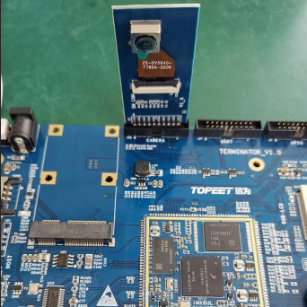
The I.MX6ULL Terminator development board exposes a CSI camera interface, supporting the OV5640 camera module from 【007】. First, we connect the OV5640 camera module to the development board, as shown in the figure below (when connecting, be sure to pay attention to the direction, the camera should face the inside of the development board, do not connect it the wrong way):
 Then we power on the development board and log in through the debug serial port, as shown in the figure below:
After the system starts, a “video1” node will be generated in the “/dev” directory. Then we enter the command “v4l2-ctl –device=/dev/video1 –list-formats-ext” in the debug serial port, and we can see the formats, resolutions, and frame rates supported by the camera, as shown in the figure below:
Can’t afford it, so it didn’t display
Then we enter the command “gst-launch-1.0 -v imxv4l2src device=/dev/video1 ! "video/x-raw, format=(string)YUY2,width=(int)640, height=(int)480, framerate=(fraction)30/1" ! imxv4l2sink” in the serial terminal, and the camera starts video capture at 640×480 30fps, the command is shown in the figure below:
gst-launch-1.0 -v imxv4l2src device=/dev/video1 ! "video/x-raw, format=(string)YUY2,width=(int)640, height=(int)480, framerate=(fraction)30/1" ! imxv4l2sink
At the same time, we can see the real-time image captured by the camera on the LCD display, as shown in the figure below:

We can stop the camera capture program by pressing “Ctrl+c” in the serial terminal.
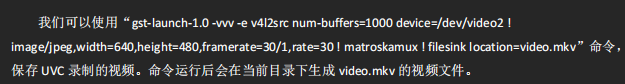
We can use the command “gst-launch-1.0 -vvv -e imxv4l2src num-buffers=1000 device=/dev/video1 ! “video/x-raw, format=(string)YUY2, width=(int)640, height=(int)480, framerate=(fraction)30/1″ ! filesink location=video.yuv” to record the video.
gst-launch-1.0 -vvv -e imxv4l2src num-buffers=1000 device=/dev/video1 ! "video/x-raw, format=(string)YUY2, width=(int)640, height=(int)480, framerate=(fraction)30/1" ! filesink location=video.yuvWe can use the command: “gst-launch-1.0 imxv4l2src num-buffers=1 device=/dev/video1 !
‘video/x-raw,format=(string)YUY2,width=640,height=480’ ! filesink location=picture.yuv”
to take a picture in yuv format.
gst-launch-1.0 imxv4l2src num-buffers=1 device=/dev/video1 !'video/x-raw,format=(string)YUY2,width=640,height=480' ! filesink location=picture.yuvWe can use the command: “gst-launch-1.0 imxv4l2src num-buffers=1 device=/dev/video1 ! jpegenc ! filesink location=picture.jpg” to save the image in jpg format.
gst-launch-1.0 imxv4l2src num-buffers=1 device=/dev/video1 ! jpegenc ! filesink location=picture.jpg02
USB Camera Test
The I.MX6ULL Terminator development board natively supports USB interface cameras that comply with the UVC protocol. We prepare a UVC camera connected to the USB HOST interface of the development board, and then power on the development board. We log in through the debug serial port, as shown in the figure below:
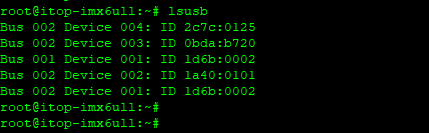
Then we enter the command “lsusb” in the serial terminal to view all USB devices in the system, and we can see that the system has detected the UVC camera, as shown in the figure below:
 Then we use the command “ls /dev/video*” to see that the device node for the UVC camera is “/dev/video2” (it could also be video3, or another), as shown in the figure below:
 Then we enter the command “v4l2-ctl –device=/dev/video2 –list-formats-ext” to check the parameters supported by the UVC camera, the result is shown in the figure below:
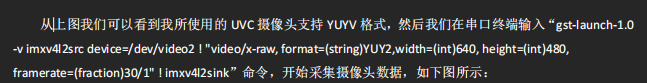 At the same time, we can see the image captured by the UVC camera on the LCD screen, as shown in the figure below:
 03
03
AP3216C Test
The I.MX6ULL Terminator development board is equipped with a three-in-one light environment sensor AP3216C. The kernel has already ported the driver for AP3216C. Now we will verify the AP3216C.
First, power on the development board and log in through the debug serial port, as shown in the figure below:
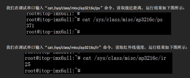
Then we enter the command “cat /sys/class/misc/ap3216c/als” to read the ambient light intensity, the result is shown in the figure below:

 04
04
WIFI Network Test
The I.MX6ULL Terminator development board is equipped with a WIFI/Bluetooth dual-module. Through WIFI we can use wireless networks. Next, let’s see how to set up the WIFI connection to the internet.
Then we enter the commands “ifconfig eth0 down” and “ifconfig eth1 down” in the debug serial port to disable the wired network, as shown in the figure below:
Then we enter the command “udhcpc -i wlan0 &” to assign an IP address to wlan0 via DHCP, the result is shown in the figure below:
From the above figure, we can see that we can connect to the internet via wifi.
05
PCIE 4G Module Test
The i.MX6ULL Terminator development board has a reserved Mini PCIE 4G interface that can connect to the EC20 module provided by 【007】. Next, we will demonstrate how to use the EC20 4G module.
First, we prepare an EC20 4G module connected to the Mini PCIE interface of the i.MX6ULL Terminator development board, then prepare a 4G antenna, connect it to the antenna socket of the EC20 module, and insert a SIM card that can connect to the internet, as shown in the figure below:
Next, we enter the command “ls /dev/ttyUSB*” in the debug serial port, and we can see that the EC20 module has created 5 virtual serial device nodes, the result is shown in the figure below:
Then we enter the commands “ifconfig eth0” and “ifconfig eth1” to ensure that all network devices are disabled, the result is shown in the figure below:
Then we enter the command “vi /etc/resolv.conf” to open the resolv.conf file in the etc directory, and enter the following three commands to set the DNS:
nameserver 202.99.160.68nameserver 221.130.33.52nameserver 221.130.33.60The DNS server addresses appear to be from China Mobile.Then save and exit. Next, we enter the command “/etc/ppp/pppd call wcdma &” to start the ppp dial-up connection, the result is shown in the figure below:Then we enter the command “ifconfig” in the debug serial terminal to check the status of the network device, the result is shown in the figure below:From the above figure, we can see that the EC20 module has successfully connected to the internet. Next, we enter the command “ping www.qq.com” to ping Tencent’s website, the result is shown in the figure below:From the above figure, we can see that we can successfully connect to the internet through the EC20 module.06
CAN Interface Test
The I.MX6ULL Terminator development board has two CAN interfaces. We can use these two CAN interfaces to verify the data transmission and reception of CAN. First, we connect CAN1 and CAN2 with a cable (when connecting can: H connects to H, L connects to L), as shown in the figure below:
The two CAN interfaces on the development board are disabled by default. We enter the command “ip link set can0 up type can bitrate 125000 triple-sampling on” in the debug serial terminal to set the bitrate of CAN0 to 125000 and enable CAN0, the result is shown in the figure below:
Then we enter the command “ip link set can1 up type can bitrate 125000 triple-sampling on” in the debug serial terminal to set the bitrate of CAN1 to 125000 (the baud rate of both parties must be set to the same during data transmission and reception), and enable CAN1, the result is shown in the figure below:
Now that we have enabled both CAN devices, we can enter the command “ifconfig” in the debug serial terminal to check, the result is shown below:
From the above figure, we can see that both CAN devices have been enabled.
Next, we use CAN0 as the data receiver, and we need to enter the command “candump can0 &” in the debug serial terminal, the result is shown in the figure below: & represents running in the backgroundThen we use CAN1 as the data sender, and we enter the command “cansend can16A0#11.22.33.44.55.66.77.88” in the debug serial terminal to send data, where 6A0 is the frame ID, and the data after # is 8 bytes. The result is shown in the figure below:
From the above figure, we can see that after CAN1 sends data, the background running CAN0 receiving program received the data from CAN0 and displayed it, and the received data is consistent with the sent data.
The data receiver and sender can also be swapped, and you can refer to the commands above (mainly explaining the CAN interface settings for the sending and receiving programs).
07
485 Interface Test
The I.MX6ULL Terminator development board is equipped with an RS485 interface. Before using it, we need to set the jumpers on the board as shown in the figure below:
According to the jumper settings in the figure above, we connect the UART3 of the i.MX6ULL to the 485 interface. I am using two i.MX6ULL Terminator development boards to verify the 485 data transmission and reception function (if you have other 485 devices, you can connect your 485 devices to the i.MX6ULL Terminator development board),485 devices need to be directly connected (A connects to A,B connects to B), my wiring is shown in the figure below:
Then we power on both i.MX6ULL Terminator development boards and log in to the debug serial terminal of both boards, as shown in the figure below:
Then we enter the command “485_test /dev/ttymxc2 0” in the debug serial terminal of board A, where “/dev/ttymxc2” is the serial device node corresponding to 485, and “0” indicates receiving data, the result is shown in the figure below:
Then we enter the command “485_test /dev/ttymxc2 1” in the debug serial terminal of board B, where “/dev/ttymxc2” is the serial device node corresponding to 485, and “1” indicates sending data, the result is shown in the figure below:
08
DHT11 Module Test
The DHT11 digital temperature and humidity sensor is a composite sensor that includes a calibrated digital signal output for temperature and humidity. It uses specialized digital module acquisition technology and temperature and humidity sensing technology to ensure high reliability and excellent long-term stability.The sensor includes a resistive humidity sensing element and an NTC temperature sensing element, and is connected to a high-performance 8-bit microcontroller. Therefore, this product has excellent quality, ultra-fast response, strong anti-interference ability, and high cost performance. Each DHT11 sensor is calibrated in a highly accurate humidity calibration chamber.The calibration coefficients are stored in the form of a program in OTP memory, and the sensor internally calls these calibration coefficients during the signal processing. The single-wire serial interface makes system integration easy and quick. Its ultra-small size and low power consumption make it the best choice for demanding applications. The product is packaged in a 4-pin single-row pin configuration for easy connection, as shown in the figure below:
The i.MX6ULL Terminator development board has already integrated the DHT11 sensor, and the provided Linux image and device tree have configured the dht11 interface. The dht11 driver uses the stable driver provided by the high version of the Linux kernel, and the root file system uses the Yocto image from the online resources. The development board must ensure that the iio interface is normal, input the following command:
cd /sys/bus/iio/devices/iio:device109
OTG Interface Host Mode Test
The i.MX6ULL development board’s OTG interface can be used as a burning interface, and after the system starts, it can be used in host mode as a USB.
During development and use, a USB flash drive is needed. This document describes how to mount a USB flash drive in OTG host mode. The operation methods are similar in Qt and Linux systems.
1 Hardware Connection
The USB flash drive needs to be in FAT32 format, as shown in the figure below. The USB flash drive is generally a large port, and an OTG to large USB port adapter is needed.
2 Mounting and Testing
As shown in the figure, after the system starts, insert the USB flash drive, and a prompt message will pop up.
Use the command “umount /mnt/otgdisk” to unmount the USB flash drive.10
Sound Card Test
1. Test Preparation
Connect headphones to the green PHONE interface and a microphone to the pink MIC interface. Use a “three-section headphone” and “three-section microphone”, as shown in the figure:
Find one to try
As shown in the figure, use the command “amixer sset ‘Left Output Mixer PCM’ on” to turn on the left channel.
As shown in the figure, use the command “amixer sset ‘Right Output Mixer PCM’ on” to turn on the right channel.
As shown in the figure, use the command “aplay /opt/lostyouth.wav &” to play music.There is sound
So I am here
Click the card below to follow me
↓↓↓

If you like it, please click
Collect
Like
View
+1
❤❤❤