Skip to content
First Author:Ruizhuo Zhang
Corresponding Authors:Torsten Brezesinski, Jürgen Janek
Affiliation: Karlsruhe Institute of Technology, Germany
The commonly used dual-electrode (2E) configuration in solid-state batteries (SSBs) is often insufficient to resolve the electrochemical processes of the anode/cathode.
Here, Professors Torsten Brezesinski and Jürgen Janek from the Karlsruhe Institute of Technology introduce a three-electrode (3E) battery configuration that utilizes a lithium titanate composite as a reference electrode (LTO-RE) during electrochemical prelithiation. In situ and ex situ electrochemical impedance spectroscopy measurements and corresponding distribution of relaxation time (DRT) analysis were conducted to reassess the relationship between the potential/state of charge/dynamics of LTO. The proposed LTO-RE maintains a stable reference potential of about 1.57 V, a minimal shift (only 8 mV over 600 hours), and negligible growth in charge transfer resistance, allowing for its long-term use in 3E SSB batteries. The time constants representing the involved kinetic processes are typically very close, obscuring reliable assessments of the contributions from different electrodes. By implementing the 3E method, the overlapping kinetic processes of the LTO working electrode and the In/InLi counter electrode can be effectively separated and identified over a wide range of time scales. Additionally, the proposed 3E configuration provides a feasible approach for in-depth studies of interfacial dynamics of individual electrodes, thereby enhancing the understanding of potential degradation processes in SSBs and ensuring stable long-term testing.
Related research findings are published under the title “Timescale Identification of Electrochemical Processes in All-Solid-State Batteries Using an Advanced Three-Electrode Cell Setup” in Energy Storage Materials.
In recent years, solid-state batteries (SSBs) and even all-solid-state batteries (ASSBs) have been considered potential follow-up technologies for automotive electrification, with high ionic conductivities observed in superionic (ceramic) conductors, such as sulfide-based solid electrolytes (SEs), paving the way for advanced SSBs. However, despite the overall promising outlook, they still face many challenges. For example, the application of sulfide-based SEs is limited by their inherently narrow electrochemical stability window, leading to interface-related issues, especially when coupled with layered nickel-rich oxide cathodes and/or high-capacity anodes during battery operation. Therefore, effective interfacial engineering of cathode active materials (CAM) and careful selection of anodes are crucial during electrochemical testing of SSBs at the laboratory scale.
In SSB testing, the dual-electrode (2E) method predominates due to its simplicity. Typically, only one electrode, usually the cathode, is the primary focus and can be regarded as the working electrode (WE). In contrast, the counter electrode (CE) serves simultaneously as the reference electrode (RE), expected to provide a stable reference potential and minimal polarization. Clearly, any conclusions about the properties of the WE in a 2E battery rely on the assumption that the CE does not contribute to the characteristics or that its own contribution can be easily subtracted. However, this assumption often fails, particularly in studies exploring the fast-charging capabilities of the WE. Alloy-type CEs commonly used in SSBs, such as In/InLi, are often considered to contribute little to the overall overpotential and electrochemical degradation, with their impacts frequently overlooked. Recent studies have indicated stability limitations of the In/InLi CE and revealed that the microstructural degradation of the In/InLi|SE interface during long-term cycling may lead to unexpected and significant interfacial resistance, emphasizing the necessity to distinguish and quantify the sources of degradation of anodes and cathodes in SSBs.
An effective method to distinguish individual electrode contributions is through the use of a three-electrode (3E) measurement system, which is a standard method in electrochemistry. Unfortunately, developing a reliable 3E setup for SSBs faces numerous challenges.
This article develops a robust 3E setup for SSB testing, initially optimizing the electrochemical prelithiation of LTO composite materials (LTO as WE) in a 2E battery. Subsequently, the material is integrated into a custom 3E battery using stainless steel (SS) wire as the current collector, functioning as the RE. The LTO, as the core material of the RE, exhibits excellent chemical and mechanical performance when combined with sulfide-based SEs, which is beneficial for long-term testing in this battery configuration. The LTO-RE contains the same SE used in the separator layer, attempting to avoid risks associated with SE heterogeneity. Overall, the proposed RE design concept is simple, provides chemical flexibility, and can be easily implemented in practical SSB testing.
Reference Electrode (RE) and Three-Electrode (3E) Battery Design
Carbon-coated LTO provided by NEI was used as the active material, showing a broad voltage platform during lithiation/delithiation. Initially, an In/InLi|SE|LTO 2E battery was assembled, as shown in Figure 1b, to adjust key parameters, including electrode composition, In/InLi CE, and, most importantly, the LTO-RE prelithiation protocol. The corresponding parameters are briefly listed as follows: (i) LTO composite material, weight ratio of LTO:Li6PS5Cl SE:Super C65 carbon black = 30:65:5 used as WE. (ii) 100-micron thick indium foil-based In/InLi used as CE. (iii) Two formation cycles at 0.1C were conducted, followed by lithiation of LTO at a capacity limit of 0.05C to ensure that LTO remained in the two-phase coexistence region during testing (Figure 1c). Using the same thickness of lithium foil (50 microns), the thicker indium foil (125 microns) caused abnormal lithiation of LTO, likely due to uneven alloying near the SE|In interface, hindering ionic transport during the initial delithiation process.
The thickness of the granular LTO composite layer is approximately 160 microns and is used for RE, as shown in Figures 1d and e. After harvesting the granules from the 2E battery, the broken LTO composite layer (attached with SE separator) was further thinned to produce individual fragments (Figure 1e). By sandwiching a thin stainless steel (SS) wire between two LTO fragments, a symmetrical structure of the RE was embedded in the SE separator layer of the 3E battery (1.47 mm thickness), as shown in Figure 1f. Figure 1g shows a practical 3E battery stack with high structural integrity. Figure 1h displays the dissected granule, exposing the internal structure of the LTO-RE. EDS mapping conducted near the SS wire confirmed the uniformity of the LTO-RE within the separator, as shown in Figures 1i‒m.
A key parameter regarding the 3E battery design is the size of the RE, which may lead to ionic blockage effects. To mitigate the hindrance of ionic transport, the design incorporated small granular LTO composite layers and linear current collectors, thus reducing the size and coverage within the 3E battery. Depending on the composition, Li6PS5Cl constitutes 65% of the prepared LTO-RE, with the same SE also used as the separator, allowing for high ionic permeability through the LTO-RE. Moreover, the non-in situ prelithiation of LTO (in the 2E battery) ensures the stability of the interface between LTO and SE, thereby avoiding potential mechanical failures that may occur near the RE with in situ lithiation strategies.
Figure 1. Preparation and Design of 3E SSB Battery.
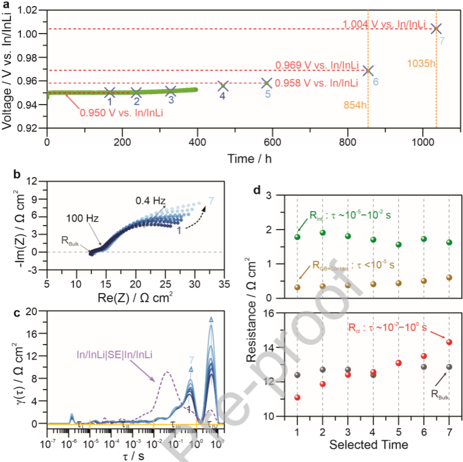
Given that the LTO-RE is embedded within the SE separator throughout the 3E measurements, it is crucial to evaluate its potential drift and chemical-mechanical stability. To this end, long-term open circuit voltage (OCV) monitoring was conducted in the In/InLi|SE|LTO 2E battery, combined with EIS-DRT analysis at selected time intervals, as shown in Figures 2a‒d. The prelithiated LTO (represented as Li4+xTi5O12) initially exhibited a potential of 0.95 V relative to In/InLi, corresponding to 1.572 V for Li. After 600 hours, a slight drift towards a higher potential of about 8 mV was observed, confirming the electrode’s ability to maintain a stable reference potential in the 3E setup. As monitoring time extended, the OCV drift became increasingly pronounced, with additional increases of 11 and 46 mV observed during the subsequent 254 and 435 hours, respectively. Overall, the trend of OCV drift transitioned from stable to accelerated increase.
Simultaneously, Figure 2b shows the change in impedance during the time intervals indicated in Figure 2a. It can be seen that as monitoring time extended, the impedance increased, corresponding to the rise in potential drift. In the EIS spectra, a depressed semicircle appeared in the mid-high frequency range (above 100 Hz), while a distinct and expanded semicircle was observed in the mid-low frequency range (below 100 Hz). To enhance the visualization and quantification of the involved kinetic processes, model-independent DRT analysis was employed.
Figure 2. Monitoring OCV of In/InLi|SE|LTO Battery Using EIS-DRT Analysis.
In Situ 2E EIS-DRT Analysis
By applying ultra-low current (0.05C) to adjust the degree of lithiation/delithiation, in situ probing of selected states of charge (SOC) was performed using EIS-DRT analysis (Figure 3a). In particular, the interfacial-related dynamics were examined under the influence of SOC variations, as shown in Figures 3b-g. When lithium ions are inserted into the LTO during discharge and charge, the composition of the indium-lithium alloy reversibly changes between lithiation state (Li0.27In) and delithiation state (Li0.15In). Compared to LTO, the evolution of peaks associated with the In/InLi electrode in the DRT pattern is relatively small. Therefore, they primarily reflect the dynamics of LTO as SOC changes. Notably, the main peaks in the τIII and τIV regions indicate that the primary SOC depends on interfacial charge transfer processes and solid-state diffusion processes within LTO particles.
Meanwhile, regarding the potential drift of the In/InLi|SE|LTO 2E battery, the authors reassessed the kinetics of LTO in SSBs. Specifically, the authors conducted a comprehensive evaluation of the stability of the proposed LTO-RE, considering potential drift and electrode behavior. It is noteworthy that under conditions of rest, low current, or minimal battery utilization, the In/InLi electrode remains stable and essentially unaffected, as confirmed by OCV monitoring and in situ EIS measurements. However, prolonged cycling leads to changes in microstructure and increased interfacial resistance. EIS-DRT analysis of the 2E battery provides important insights into the individual kinetic processes of the electrodes, which are identified by characteristic time constants. However, the overlapping impedance/time constants of the coupled electrodes pose challenges for objectively assessing their contributions to interfacial degradation, particularly in regions dominated by charge transfer processes.
 Figure 3. In Situ EIS-DRT Analysis of In/InLi|SE|LTO Battery.
Comparison of In/InLi|SE|LTO-RE|SE|LTO 3E Battery and In/InLi|SE|LTO 2E Battery
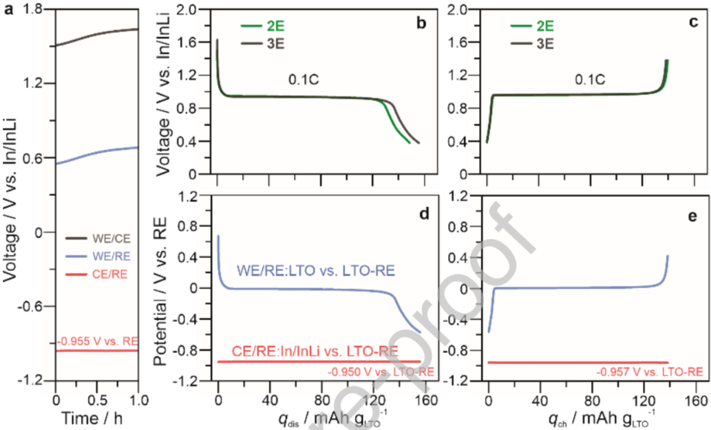
As shown in Figure 4a, after a 1-hour resting period following assembly, the In/InLi|SE|LTO-RE|SE|LTO 3E battery successfully decoupled the potentials of the two individual electrodes. The black, blue, and red curves represent the battery voltage (WE/CE), working electrode/reference electrode potential (LTO with LTO-RE), and counter electrode/reference electrode potential (In/InLi with LTO-RE), respectively. Due to the stable potential of 0.622 V for the In/InLi counter electrode under open circuit voltage (OCV) conditions, the initial (reference) potential of the LTO-RE is indirectly determined to be 0.955 V (relative to In/InLi), corresponding to 1.577 V (relative to Li/Li). During activation, at a rate of 0.1C within the voltage window of 0.38 to 1.38V, as shown in Figures 4b and c, the capacity provided by LTO is nearly the same as that of 2E.
Figure 4. Comparison of Electrochemical Performance of In/InLi|SE|LTORE|SE|LTO and In/InLi|SE|LTO Batteries.
Validation of 3E Impedance Measurements
The evaluation of the 3E battery configuration indicates that it exhibits highly reliable performance in terms of capacity and respective potentials. From the analysis of the In/InLi|SE|LTO 2E battery, it is evident that LTO demonstrates SOC-dependent impedance response, as shown in Figure 3. In the proposed LTO and In/InLi combination, the primary interfacial-related charge transfer processes were observed in the time constant region τIII (10−2–100 s), indicating severe overlap between the electrodes. Therefore, impedance measurements conducted using the 2E battery configuration cannot accurately distinguish the contributions of individual electrodes, potentially leading to misunderstandings. After electrochemical testing, the impedance of the 3E battery was measured at the end of charging, corresponding to the delithiation state of LTO and the lithiation state of In/InLi. Three independent measurements were conducted to collect data from WE/RE, CE/RE, and WE/CE, as shown in Figure 5a. The LTO WE exhibited a semicircle in the mid-frequency range, followed by a Warburg-like capacitance, indicating that diffusion processes occur in fully delithiated LTO particles. In contrast, the In/InLi CE only showed a depressed semicircle below 1.5 kHz, primarily attributed to charge transfer processes between In/InLi and SE. The total impedance of WE and CE is very close to the 2E results, except for some deviations in the high-frequency region (above 100 kHz).
Figure 3. In Situ EIS-DRT Analysis of In/InLi|SE|LTO Battery.
Comparison of In/InLi|SE|LTO-RE|SE|LTO 3E Battery and In/InLi|SE|LTO 2E Battery
As shown in Figure 4a, after a 1-hour resting period following assembly, the In/InLi|SE|LTO-RE|SE|LTO 3E battery successfully decoupled the potentials of the two individual electrodes. The black, blue, and red curves represent the battery voltage (WE/CE), working electrode/reference electrode potential (LTO with LTO-RE), and counter electrode/reference electrode potential (In/InLi with LTO-RE), respectively. Due to the stable potential of 0.622 V for the In/InLi counter electrode under open circuit voltage (OCV) conditions, the initial (reference) potential of the LTO-RE is indirectly determined to be 0.955 V (relative to In/InLi), corresponding to 1.577 V (relative to Li/Li). During activation, at a rate of 0.1C within the voltage window of 0.38 to 1.38V, as shown in Figures 4b and c, the capacity provided by LTO is nearly the same as that of 2E.
Figure 4. Comparison of Electrochemical Performance of In/InLi|SE|LTORE|SE|LTO and In/InLi|SE|LTO Batteries.
Validation of 3E Impedance Measurements
The evaluation of the 3E battery configuration indicates that it exhibits highly reliable performance in terms of capacity and respective potentials. From the analysis of the In/InLi|SE|LTO 2E battery, it is evident that LTO demonstrates SOC-dependent impedance response, as shown in Figure 3. In the proposed LTO and In/InLi combination, the primary interfacial-related charge transfer processes were observed in the time constant region τIII (10−2–100 s), indicating severe overlap between the electrodes. Therefore, impedance measurements conducted using the 2E battery configuration cannot accurately distinguish the contributions of individual electrodes, potentially leading to misunderstandings. After electrochemical testing, the impedance of the 3E battery was measured at the end of charging, corresponding to the delithiation state of LTO and the lithiation state of In/InLi. Three independent measurements were conducted to collect data from WE/RE, CE/RE, and WE/CE, as shown in Figure 5a. The LTO WE exhibited a semicircle in the mid-frequency range, followed by a Warburg-like capacitance, indicating that diffusion processes occur in fully delithiated LTO particles. In contrast, the In/InLi CE only showed a depressed semicircle below 1.5 kHz, primarily attributed to charge transfer processes between In/InLi and SE. The total impedance of WE and CE is very close to the 2E results, except for some deviations in the high-frequency region (above 100 kHz).
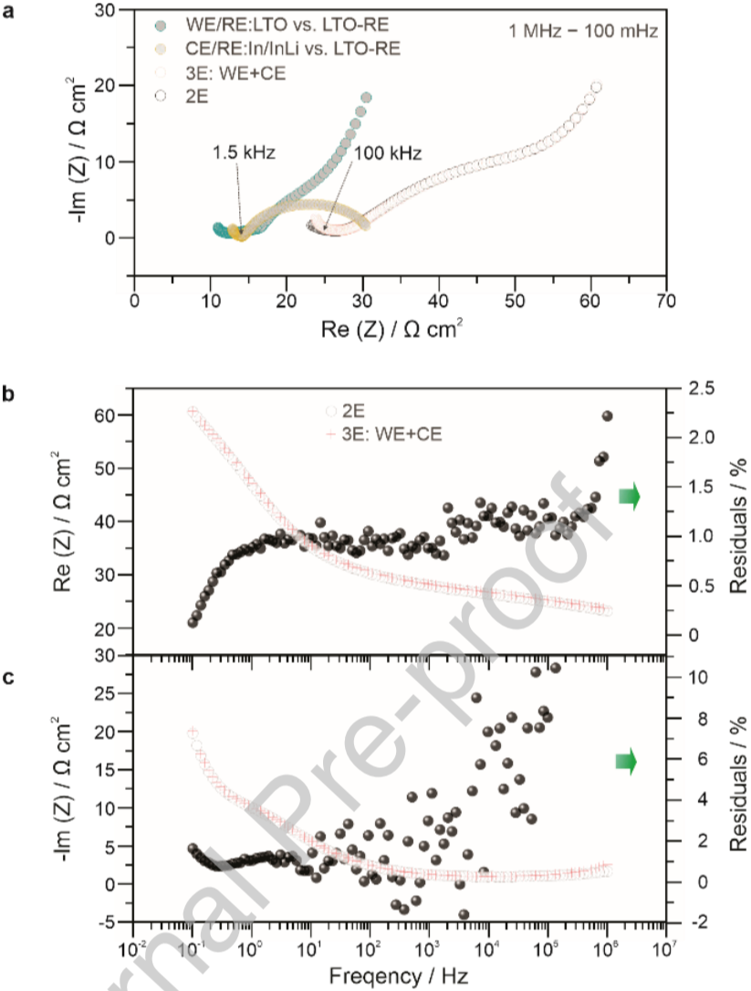 Figure 5. 3E Impedance Testing of In/InLi|SE|LTO-RE|SE|LTO Battery.
3E EIS-DRT Analysis of LTO and In/InLi Interfacial Dynamics
Figure 6a shows the DRT analysis of LTO and In/InLi, where the kinetic processes identified by different peaks exhibit significant overlap across different time scales, with clear variations in peak positions and intensities. The primary interfacial contributions located in the τIII region are associated with the charge transfer processes of LTO and In/InLi, while the slowest kinetic processes observed in the τIV region are attributed to diffusion polarization, which is the rate-limiting step in the performance of the 3E battery. In contrast, the lithiation of In/InLi shows more favorable lithium diffusivity compared to fully delithiated LTO, which is evidenced by the stark contrast in peak intensity in the τIV region. Regarding the analysis of interfacial dynamics, it is evident that in the 2E system, due to overlapping time scales, it is neither possible to fit the contributions of the processes involved using equivalent circuit models (ECM) in the frequency domain nor objectively assess the contributions of the two electrodes using relaxation time distribution (DRT) analysis in the time domain. Furthermore, the traditional frequency range divisions, particularly in the mid-low frequency range, require redefinition. The allocation should focus on attributing contributions to charge transfer at the formed interfaces (cathode electrolyte interface (CEI) or solid electrolyte interface (SEI)) and ionic charge transfer between active electrode materials and solid electrolytes, rather than simply classifying them as cathode and anode.
Figure 5. 3E Impedance Testing of In/InLi|SE|LTO-RE|SE|LTO Battery.
3E EIS-DRT Analysis of LTO and In/InLi Interfacial Dynamics
Figure 6a shows the DRT analysis of LTO and In/InLi, where the kinetic processes identified by different peaks exhibit significant overlap across different time scales, with clear variations in peak positions and intensities. The primary interfacial contributions located in the τIII region are associated with the charge transfer processes of LTO and In/InLi, while the slowest kinetic processes observed in the τIV region are attributed to diffusion polarization, which is the rate-limiting step in the performance of the 3E battery. In contrast, the lithiation of In/InLi shows more favorable lithium diffusivity compared to fully delithiated LTO, which is evidenced by the stark contrast in peak intensity in the τIV region. Regarding the analysis of interfacial dynamics, it is evident that in the 2E system, due to overlapping time scales, it is neither possible to fit the contributions of the processes involved using equivalent circuit models (ECM) in the frequency domain nor objectively assess the contributions of the two electrodes using relaxation time distribution (DRT) analysis in the time domain. Furthermore, the traditional frequency range divisions, particularly in the mid-low frequency range, require redefinition. The allocation should focus on attributing contributions to charge transfer at the formed interfaces (cathode electrolyte interface (CEI) or solid electrolyte interface (SEI)) and ionic charge transfer between active electrode materials and solid electrolytes, rather than simply classifying them as cathode and anode.
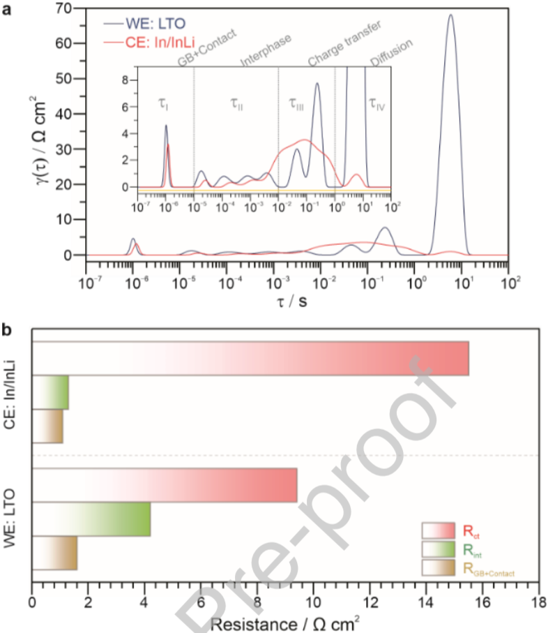 Figure 6. 3E EIS-DRT Analysis of Individual Electrodes (WE:LTO/CE:In/InLi).
In summary, this article reports a novel preparation strategy for a 3E SSB battery utilizing a composite material containing LTO as the RE. Through EIS-DRT analysis of the potential-SOC-dynamics relationship of LTO, a systematic investigation of LTO was conducted to comprehensively evaluate the prepared RE. The proposed LTO-RE provides a stable reference potential, minimal potential drift, and low growth rate of charge transfer resistance, offering optimal conditions for practical long-term testing in 3E SSBs as well as for collecting high-quality data to decouple impedance components. Meanwhile, DRT analysis clearly indicates that when inspecting contributions from individual electrodes using 2E batteries in frequency or time domains, challenges arise. The electrochemically prelithiated LTO composite material extends the application of the 3E setup to other promising SSB systems while avoiding SE heterogeneity between the RE and separator. The use of LTO as the active material in the RE is particularly advantageous, contributing to stable performance in low-temperature 3E testing scenarios. The authors believe that the setup proposed here helps bridge the performance gap between 2E and 3E configurations, providing insights into critical issues in SSB research and development.
Figure 6. 3E EIS-DRT Analysis of Individual Electrodes (WE:LTO/CE:In/InLi).
In summary, this article reports a novel preparation strategy for a 3E SSB battery utilizing a composite material containing LTO as the RE. Through EIS-DRT analysis of the potential-SOC-dynamics relationship of LTO, a systematic investigation of LTO was conducted to comprehensively evaluate the prepared RE. The proposed LTO-RE provides a stable reference potential, minimal potential drift, and low growth rate of charge transfer resistance, offering optimal conditions for practical long-term testing in 3E SSBs as well as for collecting high-quality data to decouple impedance components. Meanwhile, DRT analysis clearly indicates that when inspecting contributions from individual electrodes using 2E batteries in frequency or time domains, challenges arise. The electrochemically prelithiated LTO composite material extends the application of the 3E setup to other promising SSB systems while avoiding SE heterogeneity between the RE and separator. The use of LTO as the active material in the RE is particularly advantageous, contributing to stable performance in low-temperature 3E testing scenarios. The authors believe that the setup proposed here helps bridge the performance gap between 2E and 3E configurations, providing insights into critical issues in SSB research and development.

Ruizhuo Zhang, Aleksandr Kondrakov, Jurgen Janek, Torsten Brezesinski, Timescale Identification of Electrochemical Processes in All-Solid-State Batteries Using an Advanced Three-Electrode Cell Setup, Energy Storage Materials, https://doi.org/10.1016/j.ensm.2025.104000