In AUTOSAR, the SPI module actually divides one SPI communication into many small segments for organization and management. This approach allows for flexible control and easy expansion. Thus, we introduce the following three levels:Channel → Job → Sequence.
1. Channel
👉 Channel is the smallest unit, which can be understood as **”a block of data sent/received at one time”**. For example:
- I want to send an 8-bit data (like 0x5A) via SPI
- or receive a 16-bit data
Each send/receive task is called a Channel.A Channel corresponds to either one send or one receive of data.
✅ Key: A Channel is the unit of data operation.
2. Job
👉 Job is a collection of Channels, which can be understood as **”a series of small tasks to be completed consecutively”**.
For example:
- First send a control command (1 Channel)
- Then read a segment of status information (1 Channel)
These two Channels are packaged together to form a Job. A Job can also set:
- Which hardware SPI unit to execute
- When to switch the Chip Select (CS) signal (select or release the peripheral)
✅ Key: A Job organizes multiple Channels and handles the chip select line.
3. Sequence
👉 Sequence is a collection of Jobs, which can be understood as **”a large workflow”**. For example:
- First Job: Send initialization command
- Second Job: Read device version information
- Third Job: Send start command
These Jobs are completed in order, forming a Sequence.The entire Sequence is a complete SPI transaction.
✅ Key: A Sequence organizes multiple Jobs and controls the overall communication flow in order.
4. What is SpiExternalDevice?
SpiExternalDevice is an abstraction in the AUTOSAR configuration for “external devices connected to the SPI bus”. For example, if your board has the following peripherals:
- A Flash memory chip connected via SPI
- An ADC chip connected via SPI
- An OLED screen connected via SPI
Then,each peripheral is one SpiExternalDevice.
Each SpiExternalDevice needs to be configured with:
- Which Chip Select (CS) pin to use
- Transmission rate (e.g., 1MHz, 4MHz)
- Clock polarity and phase (CPOL, CPHA)
- Communication parameters (e.g., MSB first or LSB first)
- Associated Jobs
👉 In simple terms:
| Item | Description |
|---|---|
| SpiExternalDevice | Refers to a specific peripheral on the SPI bus |
| What does it do? | Configures and controls the SPI communication details for this peripheral |
| Configuration details? | Chip select pin, transmission rate, clock settings, communication mode |
| Associated with whom? | Will be associated with specific Jobs, which will specify which ExternalDevice to send commands to |
🔥 A simple example:
Assuming:
- Peripheral 1: SPI Flash memory, connected to Chip Select 0
- Peripheral 2: SPI OLED screen, connected to Chip Select 1
Then in the SPI configuration, you need to create two SpiExternalDevices:
<span>SpiExternalDevice_Flash</span><span>SpiExternalDevice_OLED</span>
Each needs to be configured with:
- Which Chip Select to use
- What the rate is
- Communication mode (Mode 0 / Mode 3)
- Which Jobs are allowed to send data to it
5. Difference between Synchronous and Asynchronous Transmission
👉 SPI Synchronous Transmission
Characteristics:
- Wait for results: After sending data, you must wait until the data transmission is complete before the function returns.
- Single-threaded: At this moment, the CPU is waiting for SPI to complete and cannot do anything else.
- Simple and straightforward: Suitable for small data volumes and low-speed requirements.
For example:
Spi_WriteIB(Spi_Channel1, pData);
Spi_SyncTransmit(Spi_Sequence1);// Blocking wait until SPI completes
At this time, you cannot do anything else; you must wait for SPI to finish transmitting.
👉 SPI Asynchronous Transmission
Characteristics:
- Do not wait for results: After sending data, you immediately return and continue doing other things.
- Relies on interrupts/callbacks/polling: The SPI module internally handles the transmission and can either poll for the transmission result or be configured to notify you via interrupt when the data is received.
- High efficiency: Suitable for large data volumes and high real-time requirements, such as refreshing displays or reading large batches of sensor data.
For example:
Spi_WriteIB(Spi_Channel1, pData);
Spi_AsyncTransmit(Spi_Sequence1);
// Immediately returns, CPU continues to do other work
6. Difference between Internal Buffer (IB) and External Buffer (EB) in SPI
In the AUTOSAR MCAL SPI module, two memory concepts are often mentioned:
| Name | Full Name | Meaning | Characteristics |
|---|---|---|---|
| IB | Internal Buffer | Internal buffer | Memory allocated internally by the SPI driver, where the application layer hands over data to the SPI module, which manages the transmission itself. |
| EB | External Buffer | External Buffer | Memory provided by the application layer, which the SPI module uses for transmission, and the application layer can still use it after transmission. |
In simple terms:
- IB (Internal Buffer) → The SPI module opens a small warehouse, the application hands over the goods to it, and the SPI takes the goods to send.
- EB (External Buffer) → The application has its own warehouse, and the SPI just temporarily goes to your warehouse to move goods and leaves after.
When to use IB? When to use EB?
- When the data to be transmitted is small, structurally fixed, and you want the SPI module to manage it ➔ useIB.
- When the data volume is large, frequently changing (e.g., dynamically generated), and you do not want the SPI module to manage memory ➔ useEB.
7. Program Verification
Using SPI0 and SPI1 on the board for on-board verification, with SPI1 as Master and SPI0 as Slave, the specific ports, configurations, and their wiring relationships are as follows:
| Master Pin Multiplexing Function | Master | Slave | Slave Pin Multiplexing Function | Remarks |
|---|---|---|---|---|
| CLK | PTB2(in) | PTD0(out) | CLK | Direction of pin port in parentheses |
| CS | PTB0(in) | PTD3(out) | CS | |
| SIN | PTE1(in) | PTD2(out) | SOUT | |
| SOUT | PTB1(out) | PTD1(in) | SIN |
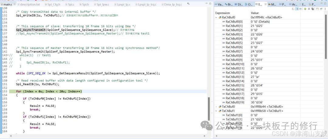
Here, the master uses synchronous mode transmission with External Buffer (EB), while the slave uses asynchronous mode transmission with Internal Buffer (IB). The SPI program and results are shown as follows:
    /* Initialize SPI */
    Spi_Init(NULL_PTR);

    /* Specify the underlying implementation mechanism used for SPI asynchronous transmission */
    Spi_SetAsyncMode(SPI_INTERRUPT_MODE);

    /* TxChBuf0  RxChBuf0 is the external (EB) Buffer */
    Spi_SetupEB(0u, TxChBuf0, RxChBuf0, 20u);//

    /* Copy data from Internal Buffer (IB) to Buffer TxChBuf1 */
    Spi_WriteIB(1u, TxChBuf1);

    /* Slave sends data in asynchronous mode */
    Spi_AsyncTransmit(SpiConf_SpiSequence_SpiSequence_Slave);

    /* Master sends data in synchronous mode */
    Spi_SyncTransmit(SpiConf_SpiSequence_SpiSequence_Master);

    /* Polling for Slave SPI transmission */
    while (SPI_SEQ_OK !=Spi_GetSequenceResult(SpiConf_SpiSequence_SpiSequence_Slave));

    /* Copy received data from Internal Buffer (IB) to Buffer RxChBuf1 */
    Spi_ReadIB(1u, RxChBuf1);