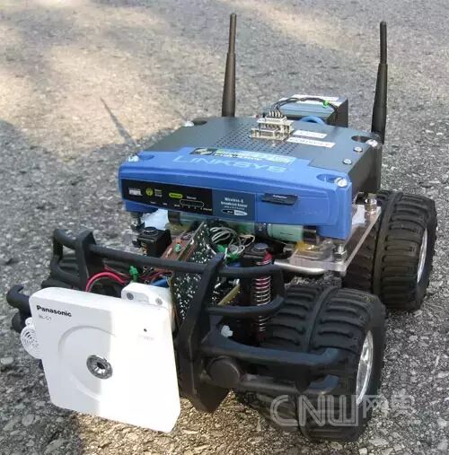
 1. IntroductionThe Wifi Robot: Essentially, it is a remote-controlled car that can be controlled remotely via the internet or a laptop’s wireless connection from up to 500 meters away. Equipped with a network camera, this car can be controlled beyond the line of sight, and it also has a speaker, allowing you to honk at people remotely.I found the Linksys WRT54GL router to be very hacker-friendly, as it runs Linux and has hardware that has been reverse engineered. There are many firmware versions available for this router, and the version used in this project is the customizable Linux firmware Open-WRT. With the software for the router, it became possible to modify a lot of hardware. Therefore, since I had access to such a cheap, modifiable embedded Linux system, I knew I could create something cool, and thus the idea of the Wifi Robot was born.The purpose of this article is to provide an overview of the project and to list some implementation details of the related software and electronic products. However, it is not a step-by-step manual on how to make a Wifi robot. Those with some electronic and software knowledge can create their own Wifi robot based on the information provided in this article. I have released all the source code under the GNU GPL v2, so I hope everyone will use this source code and try to improve it!2. Hardware Section2.1 The Car
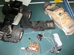
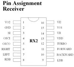
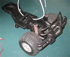
 Adding a network camera, router, heavy battery, additional circuits, and a bunch of wires to the car will greatly exceed the original design weight of the car. Therefore, considering the additional weight, you need to find an oversized remote-controlled car. Thrift stores often have some remote-controlled cars for sale, priced between $3 to $5 (excluding the remote control). I have bought many such cars for use. It is best to choose toy remote-controlled cars that are larger than or equal to 1/10 the size of a real car; do not consider those that are too small. The two remote-controlled cars in the picture below were purchased for $5 at Value Village.I have disassembled about 20 remote-controlled cars. I found that almost every car used a Realtek RX2/TX2 chip or other pin-compatible chips, and the manuals provided specific connection details for each pin. This means it is really easy to modify these cars without adding a lot of our own circuits. We can connect a microcontroller directly to these pins to control the car. Making full use of the car’s original circuits can save a lot of time and effort.2.2 Router
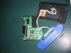
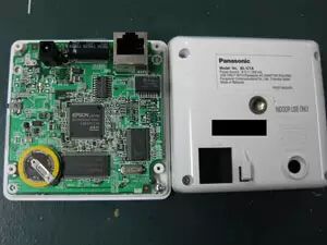
 I have modified my WRT54GL, and now it has 2 serial ports and a 1GB SD card (acting as a 1GB hard drive). In this project, the SD card is not actually used, but one serial port is utilized. One of the serial ports serves as the console port, while the other will be used for TTS/1 (text-to-speech) in the future. The firmware version I used for this project is Open-WRT White Russian v0.9, and there are more updated firmware versions available, but they are not necessary for this project.2.3 Microcontroller Selection
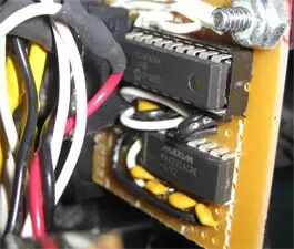
 In this project, I evaluated three different microcontrollers, and here is a brief assessment of the results.
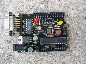
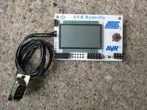
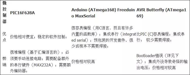 Ultimately, I chose the PIC16F628A for the following reasons:1. I have a bunch of PIC16F628A on hand.2. I am most familiar with the PIC16F628A.3. I wanted a small board, and the PIC is the smallest among the three microcontrollers.4. I wanted complete control over the functionality of the code, and the PIC is programmed in assembly language, making it suitable.Arduino (Freeduino MaxSerial) was my second choice; it is easy to install and run, and I really like it. The community support is very strong, and it is very user-friendly.I originally used the AVR Butterfly development board, but I found that there was an error in the bootloader of the AVR Butterfly that corrupted the code and prevented you from rewriting it unless you loaded a new bootloader. I spent quite a bit of time debugging and resolving this issue, but ultimately decided to abandon it. Additionally, I found the output voltage to be unpredictable, as it also had to drive integrated peripherals like LCD displays.I have the source code for both the PIC and Arduino microcontroller platforms. Both have been tested, so you can use whichever you prefer. The Arduino (Freeduino MaxSerial) is the most convenient to use, and I purchased this one.2.4 Steering Circuit
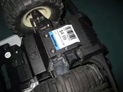
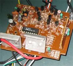
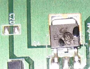 In fact, I installed two control boards on the car. The reason for this is that I accidentally burned out the original drive transistor that came with the car. Fortunately, I was able to remove the burned transistor and also the burned RX2 chip, thus saving the control circuit.The rated current of the drive transistor is 5A, and when I tried to increase the circuit voltage to 16V, the transistor “sacrificed” itself in a spectacular puff of smoke, as normally the car is powered by a battery of only 9.6V. I had to install a board from another remote-controlled car to use the drive transistor on that board. When I increased the voltage to 12V, everything worked fine, although the transistor became very hot. If we can utilize the existing circuits of the remote-controlled car without having to build our own H-bridge motor driver circuit, it will save a lot of time and money.2.5 Battery
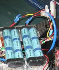 I spent over $50 on eBay to buy some high-end remote-controlled car batteries, each with a capacity of 3800mAh, along with a 1.8A smart charger. Each battery takes about 1.5 hours to charge from completely dead.I replaced all the remote-controlled battery connectors with standard ATX power supply Molex connectors. This way, I can connect them with my existing cheap connectors and easily make a splitter connector for power measurement. When connected in series, the total voltage of these fully charged batteries is about 16V.2.6 Power Rails
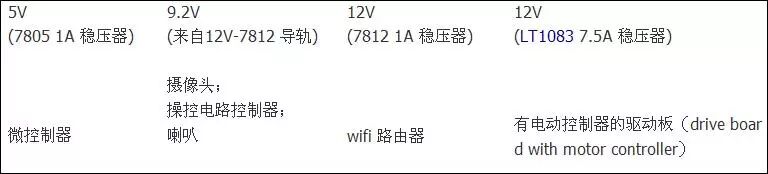 The 9.6V rail is powered by the 7812 12V rail, but we first need to connect four diodes in series with the 7812 12V rail. The reason for this is that each diode requires 0.7V (not exceeding 0.7V in practice), and by connecting these four diodes in series, we can reduce the total voltage of the 7812 12V rail by about 2.8V, resulting in approximately 9V, which is the voltage required for our devices.The rated current of the 7812 voltage regulator is only 1A, but the power consumption of the motor will greatly exceed this. Therefore, I bought a 7.5A 12V voltage regulator from Digikey for less than $14 and added a heatsink on it, as I estimated it might get very hot during operation. However, in multiple actual uses, I found that it did not even get warm, so a heatsink was not necessary.I did not want to risk burning out the control circuit, so I placed it on the rail closest to the remote-controlled car battery. The camera operates at 9V, and the speaker is similar, so I placed these devices on the 9.2V rail.
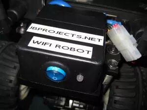
 All the power electronic devices are mounted on a prototype board and stored in a project box.2.7 Microcontroller CircuitPIC
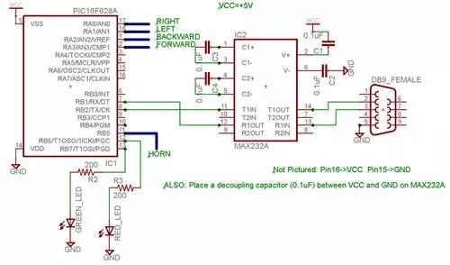 Arduino Wiring GuideSignal Arduino Pin Forward Digital Pin 8Backward Digital Pin 9Left Digital Pin 10Right Digital Pin 11Green LED Digital Pin 7Red LED Digital Pin 6Speaker Digital Pin 5Simply connect the Freeduino MaxSerial serial port to the router’s serial port using a standard serial cable.
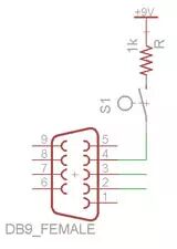 The Freeduino MaxSerial uses serial pin 4, which is the DTR (data terminal ready) pin, to reset the microcontroller and allow it to download new code. During normal computer operation, this pin operates at 10V or -10V, depending on whether the serial port is connected. However, this pin is grounded on the router’s serial port, and when the router’s serial port sends data, the MaxSerial resets, which is not suitable for this project. We require the DTR pin to be raised to +9V. Through hardware modification, we added a program lock mode to prevent uploading new code and to prevent the serial port from resetting the microcontroller.Note: If you are using the USB interface version of Arduino, you should only need to connect the RX and TX pins to MAX232A and then connect to the router’s serial port, and you may not need to make hardware modifications. However, I only have the MaxSerial version, so I cannot verify this point.2.8 Camera
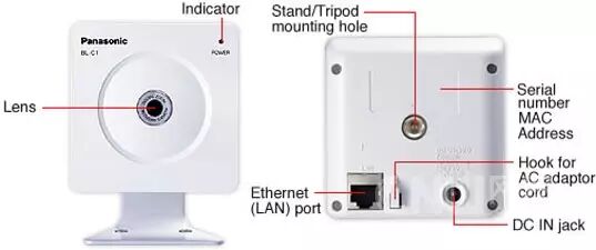
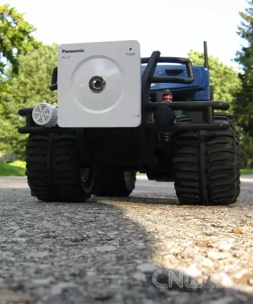
 One of the coolest aspects of this project is being able to drive the car beyond the line of sight. This is accomplished with a network camera. The camera I chose is the Panasonic BL-C1A, which is essentially the cheapest wired network camera, and its driver software can only be used on Windows systems, but it is completely sufficient. Moreover, as noted by two reviewers, this camera has a very practical web interface.
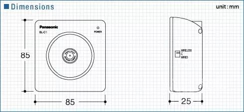 The video quality of this camera is quite good. However, even with a good connection, it often pauses for about a second before resuming normal operation. I guess this is due to its controller not having a strong enough autofocus capability, but overall, I still like this cost-effective camera.2.9 Speaker
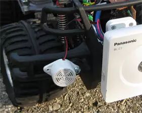
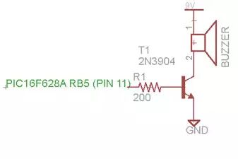 I thought it would be fun to honk at people with the remote-controlled car, so I added a speaker, which was easy to implement. I bought a $3 buzzer and connected it to the microcontroller with a transistor.2.10 Hardware Installation
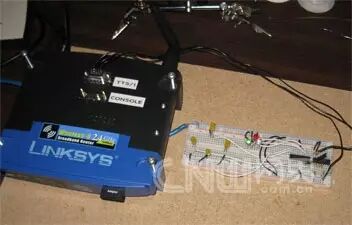
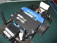
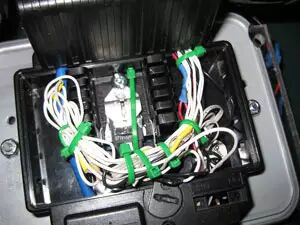
 The PIC control board is securely fixed to one side of the car. I drilled many holes in the car frame to pass the wires through, and all wire lengths were made longer than actually needed to allow for free adjustment of the positions of the components before final fixing. Once all components were securely fixed, I used a cable tie to tighten the excess wire. This project used about 30 wires, not including the Ethernet cable.
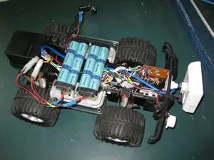 A project box is mounted on the top of the car, and all other power circuits are placed in this project box, except for the LT1083 7.5A voltage regulator, which is mounted on the bottom of the remote-controlled car. The reason I did not place the LT1083 7.5A voltage regulator in the box is that it was added after I burned out the first control board, and it was most convenient to mount it on the bottom of the car.When the router starts, an LED mounted on the back of the project box begins to emit red light. When the router sends an ‘alive’ message to the microcontroller, this LED turns green, indicating that I can connect the VB client application. This LED is very useful for debugging the system.
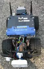
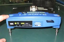
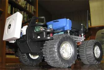 I used some hot glue and cable ties to secure the battery. Additionally, the router is a bit too wide for the base of the remote-controlled car, so I made some modifications by adding two pieces of acrylic to widen the base of the remote-controlled car.2.11 Future Components to be AddedThe following items should be interesting additions that I want to include:1. Headlight: Essentially a super bright LED, which should be easy to add to the micro circuit.2. Current Sensor: Can report the amount of current used by the car and display it in the VB application. The controller can read the sensor data and send it back.3. Software SectionThis project requires three types of software:1. VB6 Wifi_Robot client application (running on Windows);2. CarServer written in C language for the router, which runs OpenWRT WhiteRussian v0.9 (Linux version);3. Microcontroller firmware.I have provided tested firmware for the PIC16F628A microcontroller and Arduino (Freeduino MaxSerial), and the related source code is released under the GNU GPL v2.Assuming you have a Linksys WRT54GL installed with OpenWRT WhiteRussian v0.9 and connected to the internet, you can refer to the installation instructions below.Installing CarServerIf you just want to use the software, configure SSH on your router and run the following code:# cd /tmp# wget http://www.jbprojects.net/projec … server_1_mipsel.ipk# ipkg install ./carserver_1_mipsel.ipkCompiling and Installing CarServerIf you want to see how it works or want to modify the code yourself, you need to download the OpenWRT SDK (Linux version) and follow Eric Bishop’s Writing and Compiling A Simple Program for OpenWRT to compile the software (just refer to the first part).Makefile place in /OpenWrt-SDK-Linux-i686-1/package/carserver/Makefile place in /OpenWrt-SDK-Linux-i686-1/package/carserver/srccarserver.c place in /OpenWrt-SDK-Linux-i686-1/package/carserver/srcThe compiled ipkg will appear in /OpenWrt-SDK-Linux-i686-1/bin/packages. Then copy the code # scp carserver_1_mipsel.ipk root@<router_ip>:/tmp/. to your router, configure SSH, and install it.Related ResourcesThere is a great eBook about the WRT54G series routers: “Linksys WRT54G Ultimate Hacking.” This book teaches how to add a serial port, how to set up software, and a bunch of hacking tips. I have contacted one of the authors of this book, and it is not free, but you can read it on Google Books.3.1 How to Get the Serial Port WorkingWe need to utilize TTS/1 (text-to-speech), so if you only added one serial port, ensure that this port is used for speech synthesis. Assuming you have installed OpenWRT WhiteRussian v0.9, run the following commands.# ipkg update# ipkg install setserial# cd /usr/sbin# wget http://www.jbprojects.net/projects/wifirobot/stty.tgz# tar -zxvf stty.tgz# chmod 755 sttyAdd the following statements to /etc/init.d/custom-user-startup to make the serial port work after startup and to automatically start CarServer./usr/sbin/setserial /dev/tts/1 irq 3/usr/sbin/stty -F /dev/tts/1 raw speed 9600/bin/carserver &3.2 Running the Wifi Robot Client Application
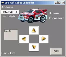
This article’s source address: www.jbprojects.net/projects/wifirobot/
If you find this article valuable, please click the “…” in the upper right corner to share!
Interesting, in-depth, and technical, please scan the QR code to follow “Robot Network”