This article is a highlight from the Kanxue forum. Author ID: Zeng Banxian
The firmware verification defect of Jlink V10 was previously published along with a flashing tool, but the defect requires flashing once and then flashing back.
Before the release, during a discussion in a mobile device development group, a group member mentioned that V10 would check the firmware signature, asking how I would handle it. I said I could place code in the space outside the signature area, and I could fit 500 bytes in there completely.
He indicated that older versions had a bug allowing arbitrary writes, but it had been fixed. Although he didn’t disclose details, I figured that if he could find me, he could find a way too.
I then examined the command handling one by one and indeed found a stack overflow bug. This bug is not the one he mentioned, and the stack is too small to exploit easily.
I disagree; counting bytes to write code is a fundamental skill for us middle-aged programmers!
Let’s first look at the disassembled code of the problematic function fine_write_read:
usbrxbuf(arg, 12); // Receive three lengths usbrxbuf(writebuf, arg[0]); // Can overwrite LR readed = syncM0FINEGPIO(writebuf, arg[0], replybuf, arg[1]); memcpy((char *)&arg[7] + arg[1], &readed, sizeof(int)); // Clear 4 bytes at any address usbtxbuf(replybuf, arg[1] + 4);
This code has a user-controlled buffer length issue. It first receives three length variables, which I named writelen, readlen, and somelen. The first writelen controls the size of the next buffer reception, and then the usbrxbuf function receives the corresponding length of bytes into writebuf, which is allocated on the stack. This can lead to an overwrite, overwriting LR.
Next, we look at the destination of memcpy, which is the address of writebuf plus the second length offset equals the final address, copying the 4-byte readed value to this address. This constitutes an arbitrary write; normally, the readed value equals the readlen, but it can be abnormal.
This writebuf is an array on the stack, let’s open the stack structure window to take a look:
-0000003C readed DCD ?-00000038 arg DCD 3 dup(?)-0000002C writebuf DCB 16 dup(?)-0000001C replybuf DCB 24 dup(?)-00000004 LR DCD ?+00000000 ; end of stack variables
As long as we write 0x2C bytes from the writebuf location, we overwrite the saved LR. Since the program prologue is a simple PUSH {LR}, there are no other register values to restore.
The simplest exploitation method is to let the usbrxbuf function write 0x2C bytes to writebuf, overwriting the saved LR to the address of our written buffer. First, we need to know the specific value of sp when executing this, so we can jump to our written code.
I wrote a small tool that triggers the fine_write_read processing function through USB commands, giving the length writelen as 2C, with the content of this 2C being all AA, then using SWD to connect to the Jlink chip. I set a breakpoint at the BL usbrxbuf, executed the command to break, and checked the sp value at that time, which was 100840A0. After executing usbrxbuf, writebuf, replybuf, and the return address (LR) were all filled with AA.
Because there are three BLs from BL usbrxbuf until the function returns, to make the stack LR effective, it must execute to POP PC. We sequentially execute these three BLs, and after executing the first BL syncM0FINEGPIO, a problem arises; the AA we sent in was cleared by this function! The 0x2C bytes starting from replybuf were cleared, exceeding the LR on the stack and clearing into the parent function’s stack.
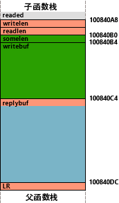
To make it more intuitive, I sketched the stack of the fine_write_read function. As the name suggests, this function is used for communication between the host computer and the development board using the FINE interface (Renesas protocol). The host sends out data of writelen length, and the debugger sends it to the development board through GPIO pins, then reads back data of readlen length into replybuf and sends it back to the host along with the read length.
We certainly don’t want replybuf to be overwritten, so if readlen is set to 0, it should normally return 0 as well, and no value should be written to replybuf; only memcpy would overwrite the first 4 bytes of replybuf with 0 (readed).
After stepping into syncM0FINEGPIO and debugging, I found that after executing a certain memory write instruction, the replybuf in the stack along with the subsequent LR was instantaneously cleared.
This instruction operation is [20000008]=1, this address is described in the data sheet as shared memory between M4/M0. After analysis, this syncM0FINEGPIO function is a cooperative function that sets parameters for M0 and waits for it to complete.
APP:1A016864 008 20 60 STR R0, [R4] ; executing here will destroy LRAPP:1A016866 008 BF F3 4F 8F DSB.W SY
At this point, we need to discuss the hardware characteristics of the J-Link V10. Its CPU has M4/M0 cores; it seems that to keep the GPIO simulation protocol’s timing stable without being affected by RTOS, J-Link programmers use M0 to handle protocol simulation separately. 20000008 is the state variable between M4/M0, where M4 switches to state 1 and waits for 0, while M0 waits for 1 to complete and then switches to 0 and continues waiting for 1.
But why would M0, which should skip reading according to readlen, overwrite our replybuf according to writelen? To overwrite correctly, writelen cannot be set to 0.
I suspect it’s because we did not go through the preceding operations and directly sent the FINE request; the program running in M0 is not prepared for the FINE protocol. I do not have a Renesas development board, so I cannot connect to the FINE interface to see the firmware command execution process.
However, through flipping and guessing, I discovered a select_if command; when selecting interface number 3, the M0 app (the function at the Reset Vector address) matches the FINE read/write.
After adding the select_if command to our tool and debugging, we successfully reached POP {PC}.
Next, we need to consider ways to insert more code. Currently, the space we can utilize is divided into two segments; somelen should be a reserved field in the fine_write_read command, so it is not used in the function and will retain its content. The green area starting from it can hold 0x14 bytes of code, and the first 4 bytes of replybuf will be overwritten by memcpy with the readed value returned from M0’s program, so we need to avoid those 4 bytes. There is also a blue area of 0x14 bytes after LR that can hold code.
So can the parent function’s stack continue to be overwritten as code? In reality, it cannot. After completing the usbrxbuf function, we can observe that the parent function’s stack can indeed be overwritten, but when the usbtxbuf function is called to send a response, the device will crash and restart, failing to return to POP {PC}.
The usbtxbuf function will send replybuf, with a length of readlen + 4. Looking at the usbtxbuf function, we see that if either buf or len is 0, the function will return directly without calling other sub-functions. So if we set readlen to -4, won’t this sending function just return directly?
That said, readlen is also passed to M0 as the length of bytes read into replybuf from the GPIO pin; if we pass a negative value, will M0 start writing replybuf uncontrollably?
After examining the M0 app, I found that the reading part checks if readlen is not 0, then reads at least one byte before checking if the number of bytes read is less than writelen. This check is done with BLT, which is signed. Therefore, after reading 1 byte, the loop condition 1 < -4 does not hold, and it will not loop.
However… an unexpected complication arises; when M4 passes the readlen parameter to M0, it shifts left by 3 bits to convert the readlen byte count to bits, and then in M0, it shifts right by 3 bits back to bytes. Therefore, passing FFFFFFFC (-4) drops the high 3 bits, resulting in 1FFFFFFC (536870908). The programmer’s seemingly meaningless conversion just happens to block this bypass of the sending function.
But we shouldn’t despair, because J-Link does not allow M0 to execute from flashA (presumably because placing it in sram is zero wait cycles, making the simulated timing more accurate), but instead in sram0. Therefore, we can dynamically patch M0’s app.
We can do this in two steps; the first step is to not overflow, and after patching M0’s app, we just return, because when our payload executes, M0 is in a state of waiting for 20000008, and since M0 has no icache, patching another location in the next round of GPIO operations will execute the patched code. What we are patching is this right shift by 3 code LSRS R5, R5, #3, which we directly patch to EORS R5, R5, so that the next cooperative function will think readlen is 0, thus not affecting replybuf. Externally, M4 appears to still have readlen as -4, which can still be used to bypass the usbtxbuf sending function.
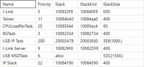
Testing proves feasible; receiving a size of 12C has already corrupted the parent function’s stack, even penetrating the task’s stack space, but usbtxbuf did not use the stack and returned directly, finally reaching the POP {PC} process to our code. In testing, the 12C actually wrote into the IP stack’s stack, but as long as I disable interrupts in my payload, RTOS will not switch to the IP stack thread.
This is the stack allocation table for each thread of the embOS in the factory version firmware.
Thus, the space we can use to place code has greatly increased, as adjusting readlen allows us to adjust the arbitrary write bug, and the value of readed will correspondingly be copied to the location of replybuf -4, allowing us to use 0x10 + 0x18 + the overflowed part length. I haven’t tried the maximum amount to write; it should be fine as long as it can be received successfully without crashing.
Now, can we call it a day? Obviously not perfectly. With this kind of damage, after executing our payload, we can only restore the environment by rebooting. Is there any way to continue returning to execution? For example, writing to other free spaces?
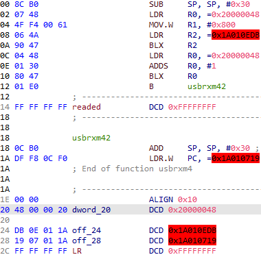
Of course, there is, and it just happens to fit within a size of 0x28. The target address is chosen as 20000048, which is a place that the IP Stack will access, presumably reserved for code related to networking functionality. Alternatively, we could choose the 10000160 location in sram0, speculating that the Segger programmer reserved the entire sram0 for exclusive use by M0, as the FINE M0 APP only used the first 0x160.
The first empty readed here is the target of memcpy, and the second empty LR is the return address on the stack.
Note that the sub sp, #0x30 here is because we need to call usbrxbuf in the payload, and when executing our payload, sp just points to the address after the end of the payload; the first call BLX R2 is usbrxbuf, and its child function will write to the stack, moving forward and corrupting the end of our payload.
Of course, subtracting 28 is also possible because only after executing the blx r2 instruction does it enter the child function, and the preceding few instruction spaces are no longer needed.
However, this does not satisfy me; I am pondering whether we can activate and maintain M0’s reset signal and overwrite our self-made M0 App into sram0, and then keep the App executing in the “background”?
After simplification, loading code requires 0x2C continuous space because if our M0 card resets, it will cause the next fine_write_read command to fail to return from the dual-core cooperative function syncM0FINEGPIO, which cannot be split into two executions. Can we move the position where readed is stored further forward? The answer is certainly yes!
In fact, this readed has already moved forward by 4 bytes due to our readlen; if we continue moving forward, won’t it move outside the current function’s stack space? But reducing readlen will also cause the length to be negative during the final usbtxbuf, resulting in infinite sending. Since memcpy is performed first and then usbtxbuf, can we make readlen -0x18 when taking parameters for memcpy, but after execution write -4 back to the readlen position, so that usbtxbuf can sum to 0? As long as we can keep M0 returning -4.
I improved the code for patching M0, adding an extra place to make the return become -4.
sram0:10000150 loc_10000150 ; CODE XREF: FINE_Reset_Handler+10A↓jsram0:10000150 000 40 1E SUBS R0, R0, #1sram0:10000152 000 FD D5 BPL loc_10000150sram0:10000154 000 20 46 MOV R0, R4
The last sentence R0’s value will be written to 20000024 later, to be read back as a return value by the M4 synchronization function; originally, it was passing the value from R4 (readed) to R0, but I changed it to subs R0, #4, because when looping to this point, R0 is 0. Thus, when M4 retrieves it, it will get -4.
To summarize, after the first patch returns, the second overflow occurs, and the host computer sends readlen as -0x18, causing memcpy’s target to point to readlen itself. After executing memcpy, readlen becomes -4 as given by M0, and when calling usbtx, this readlen + 4 = 0 will not call the usb function and will return directly, thus avoiding the payload destruction function execution issue.
Thus, our tool now has three schemes:
(1) Classic In-Place Overflow, requires patching M0 plus negative offset jump sending. The complete payload covers from the current function stack backward. The downside is that after execution, it must restart, and no USB sending can be done in the payload code.
(2) Free Memory M4 Execution. During the first overflow, an additional call to usbrxbuf receives the complete payload to a free memory location, then jumps to execute and return. Since the stack is not corrupted, USB sending can continue in the payload.
(3) M0 Exclusive App Background Execution. During M4’s preparation phase, replace the entire M0 App, and from then on, when we send the fine_write_read command, it can respond to processing through the original cooperative function.
However, after testing, scheme 3 using a simple refresh method (holding the M0 reset and overwriting its program code after releasing the reset control bit) causes the system to restart after 500ms. Using the complete refresh function bootm0app in the firmware does not restart, but we need to parse the function address separately.
Is this the end? Not yet, there is still the most important step: compatibility.
To release a mature exploit, we need to be compatible with as many firmware versions as possible. We need to know the value of sp, the value of usbrxbuf, to fill in the pointer at the end of the payload under different firmware versions. One way is to collect all drivers, decompress each firmware, and analyze manually.
Another way is to use a program to find it automatically. Although we initially obtained SP through real machine debugging, I realized at this moment that the value of SP could be obtained by subtracting the SP difference at each call from the initial value during the main thread’s execution. The initial value should be the bottom value of the stack space passed in when RTOS was created, as ARM traditionally requires 8 compatibility, and the initial value also needs to be aligned to 8 once.
The IDA script’s function is to find main based on IAR features, then extract the stack initial value, locate the usb dispatch function in the main thread function, find the usb command handling program array, and locate the fine_write_read function, subtracting the SP offsets from these three jump points.
Then considering that users’ machines do not have IDA and need to run a server to run idapython, can we find it locally using a regular decompilation library? I previously wrote some parsing while writing insanelinker, but only for individual instructions. I was too lazy to improve it and thought it would be better to look for open-source solutions!
Capstone is a bit large, but I found a couple of lighter alternatives that were even worse, and ultimately I ported a version from the IDA script for capstone. Because it can’t determine function endings like IDA, nor can it provide SP offsets, its universality is certainly not as good as the IDA script.
After adjustment and verification, the V10 firmware can find all features up to the latest version, and I also tested V11, finding that it is applicable up to 7.52a, but in 7.52b, it locates incorrectly at the first step, indicating that from this version on, it is likely no longer compiled by IAR, but by SES (Segger Embedded Studio), where LDR has basically changed to MOVW/MOVT combinations, making it difficult to search, and usbrxbuf has all become inline calls, static analysis can only obtain secondary pointer addresses.
This results in the “M4 receiver” being unable to squeeze out the code to obtain the receiving function address, but it can be bypassed, for example, by overflowing a few more times to piece together a receiver and execute it, or by obtaining the function address after the first overflow and sending it back to the host for assembling the receiver.
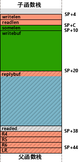
At the same time, due to the compiler change, the new fine_write_read’s stack bottom has added R4, R5, R6, and we need to know the original values when we overwrite. For example, in 7.60a, the value of R4 before execution is the corrected command index, and R5 and R6 can be found in the main thread by looking for MOVW/MOVT combinations, but in 7.52b, R6 is the cmd related.
Therefore, static analysis for general processing has become very difficult (the reasons will be discussed later), and we need to think of a way to create a simulator that can simulate peripheral units, or simply use actual hardware to run through these versions, set breakpoints, and record, then provide a service to remotely receive new test firmware uploads for flashing.
Another obscure method is to look at the read_emu_mem command; it is quite complex and should also protect these registers. Indeed, the entry is PUSH.W {R4-R9, LR}. So can we use it to read the values of R4-R6 in the current stack and then assemble them in front of LR in fine_write_read? It is completely feasible.
Because the main thread here is just an infinite loop, different commands all go through the same BLX instruction call, unless one of these three registers stores the command index, but this index is no longer used after obtaining the command pointer.
This reserve is used as a last resort; first, let’s try static analysis. I improved the search code to continuously track MOVW/MOVT pairs before encountering a BLX call to the USB command, recording the last combination values of R4, R5, R6 obtained.
Comparing the output results, so far, the static assembly analysis and dynamic acquisition are the same. The hidden danger of my parsing method is that it does not handle jumps, so if the later code initializes R4, R5, R6 and then jumps back to execute the cmd code, my recording method will fail. However, so far, I have not encountered this issue in the current version.
Next, the loader must also adapt to the SES compiled version V11 firmware, but I found that the temporary variable readed in the SES version has moved from the top of the stack to the end, occupying the last 4 bytes of replybuf, because the replybuf code was originally 0x14 in size, but the IAR version had 4 bytes of useless space at the end due to 8-byte stack alignment.
When replybuf is restored to its original form, there are 4 bytes less available space. However, I found that one of R4, R5, R6 in the stack is always the cmd index, because the cmd index register is not referenced after obtaining the command pointer until preparing for the next reception. Can we dynamically move the end of the LDR pool to its corresponding position?
After adjustment, I added relocation processing and successfully stuffed the M4 loader’s code into the latest V11 stack, with an extra two bytes remaining.I wrote a blinking LED payload, which executed normally and continued without crashing.
So what if the cmd index is not R4, R5, or R6? Because in our scheme 2, the return is the function calling cmd, so we can restore the corresponding register values before returning in the payload, but this requires cooperation from the payload.
If we don’t want to cooperate in the payload, then this process must also patch M0App once, to free up four bytes at +14.
I am still pondering how to provide this for legitimate users and not let it be used by counterfeit merchants. Using the USB protocol’s signature verification command is unreliable. I suspect that those counterfeit versions that cannot be upgraded have also modified the signature verification. My idea is to read the bootloader to check the code area and some parameters, ensuring first that the bootloader has not been changed, CRP debugging protection exists, and then check that the serial number and OTS signature are not empty.
I tested on my V10 and was able to identify modifications to the bootloader.
Since I do not have a genuine V11, I have not tested it yet. I inadvertently heard that a group friend has a genuine V11 and specifically sought his help, adding legitimate verification for V11.
Now I can support all versions of V10/V11; let’s think about what fun things we can write?
(1) Blinky, the classic LED flash.
//LPC_SCU->SFSP2_4 = 0x54; // P2_4 -> Fun4, No Pullup //LPC_GPIO_PORT->DIR[5] |= 1 << 4; // GPIO5[4] Output for (int loop = 12; loop; loop--) { LPC_GPIO_PORT->CLR[5] = 1 << 4; // ON FeedWWDT(); delay200ms(); LPC_GPIO_PORT->SET[5] = 1 << 4; // OFF FeedWWDT(); delay200ms(); } return;
GPIO5[4] is the red light, and the main program has already initialized it for us. The first two initialization steps can be omitted. The effect is that the red light blinks 12 times, and the machine continues to run normally. Because this chip’s WWDT watchdog cannot be turned off once it is activated, if the time exceeds 500ms, it must feed the dog, hence the inclusion of the feeding call.
(2) SWDUnlock, removing debugging restrictions.
The V10 circuit board reserves a jtag/swd debugging interface, but because it was set with a CRP code read protection at the time of release, this interface cannot be used for debugging (and thus cannot be used for dumping). However, we can modify the page where the CRP flag is located through code to turn it off.
Since the LPC4322 has built-in flash operation functions in its ROM, we can complete the repair through init, prepare, erase, prepare, write five steps. Since the return stack is in the upper function, there is approximately Dxx-sized stack space available for use in the payload.
(3) Remove bootloader firmware verification or flash a custom bootloader.
Segger has added RSA signature verification to ensure that the firmware is official. Although the previous post mentioned that this RSA check does not cover the entire firmware, allowing us to insert our code, if the bootloader is patched, we can completely create our firmware. Segger’s trust strategy is that the bootloader trusts itself not to be modified, while distrusting the firmware to check the firmware.
(4) Let JLink automatically patch user-developed firmware.
This is quite special; assuming we know the other party is a developer or a paranoid wallet user who compiles firmware for burning without internet access. If we can access their debugger’s USB connection, we can use the above methods to patch the firmware in the debugger, implanting backdoors into the burned product firmware, such as specific confidential devices that can only be accessed by flash code. However, unfortunately, this is unlikely to be generic, as we cannot buffer the entire firmware for analysis, only stream patching.
This bug exists in JLink V9, JLink Pro, and the latest firmware of JLink Wifi, and it is estimated that as long as Segger supports products with the FINE protocol, they all have the same vulnerability. The Wifi version may not even need a USB connection to overflow. The Pro version does not have an M0 co-processor, so it cannot use the negative offset trick.
I reported this bug to Segger on January 5, but I do not know why the manufacturer did not take it seriously. Later, I followed up and was told that the password I provided could not open the compressed file. After another follow-up, I was told that the product manager was ill. Well, until the time of release, I will publish the universal JLink V10/V11 firmware.
In conclusion, embedded environments have their inherent characteristics; the downside is that memory resources are extremely limited, and VFT is used less. Some function pointer-based exploits cannot be used here. The upside is that the execution environment is relatively clean, with no interference from other processes/OS. As long as no bugs are produced, the functions triggered in the same way will behave the same way, regardless of how many times, and can even be statically calculated on a computer.
Special thanks: thxlp, XX, Status: Headcrabed.
The tool has been uploaded, with some restrictions to prevent taobao. It currently has features such as LED flashing, feature removal, and mutual conversion between V10/V11.The code has been sent to GitHub.
Kanxue ID: Zeng Banxian
https://bbs.pediy.com/user-home-670.htm
*This article is originally by Zeng Banxian from Kanxue Forum, please indicate the source from the Kanxue community when reprinting.

# Previous Recommendations
1. CVE-2022-0995 Analysis (Kernel Out-of-Bounds watch_queue_set_filter)
2. ZJCTF2021 Reverse-Triple Language
3. Docker-remoter-api Penetration
4. Writeup-ROP Emporium fluff
5. Detailed Analysis of APT28 Samples
6. CVE-2016-0095 Privilege Escalation Vulnerability Learning Notes