Implement the bidirectional movement of the car using S7-200’s automatic control.
The control process is to press the start button, the car moves from left to right (and then back from right to left). When it reaches the right (or left), it hits the limit switch on that side, and the car automatically returns. Upon hitting the limit switch on the opposite side, it again returns. This back-and-forth movement continues until the stop button is pressed, at which point the car stops moving.

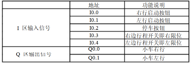
➤I/O Allocation Table
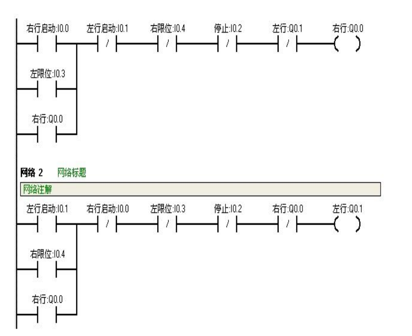
➤Ladder Diagram Program
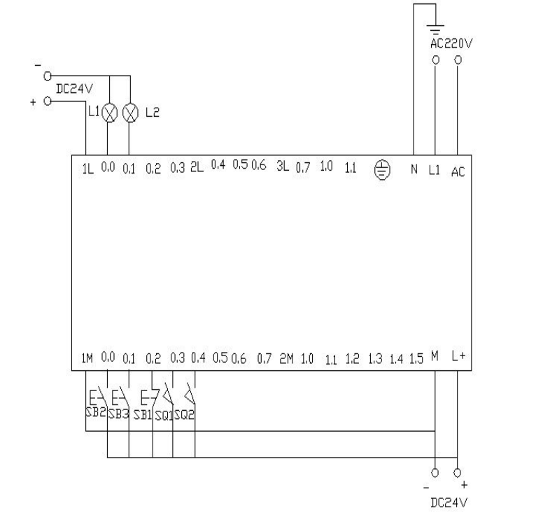
➤PLC Wiring Diagram
➤Program Debugging and Result Analysis
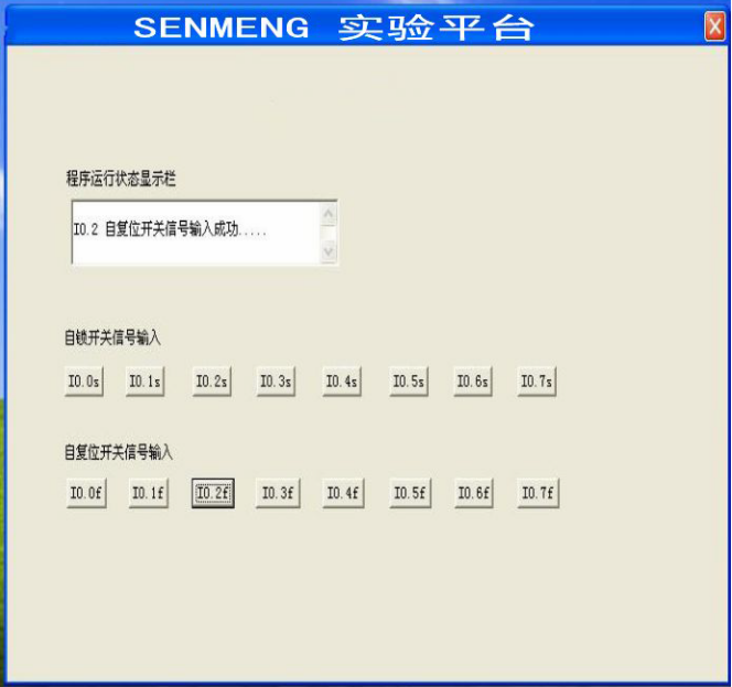
When SB2, i0.0 (click i0.0f with the mouse) is activated, Q0.0 is activated, and the car moves to the right (indicated by the light Q0.0 being on).
When the car hits the right limit switch SQ2, i0.4 (click i0.4f with the mouse to simulate SQ2 being pressed), it moves to the left (the indicator light Q0.0 is off, and the indicator light Q0.1 is on). When it reaches the left side and hits the left limit SQ1, i0.3 (click i0.3f), it moves back to the right (the indicator light Q0.1 is off, and the indicator light Q0.0 is on).
This back-and-forth movement continues until the stop button SB1, i0.2 (click i0.2f) is activated, at which point the car stops.
Appendix: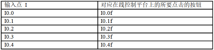
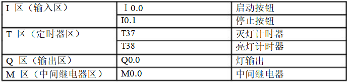
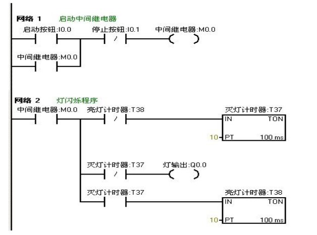
When the start button is pressed, it requires the light to be on for one second and off for one second within two seconds, flashing repeatedly.
➤I/O Allocation Table
➤Ladder Diagram Program
➤PLC Wiring Diagram
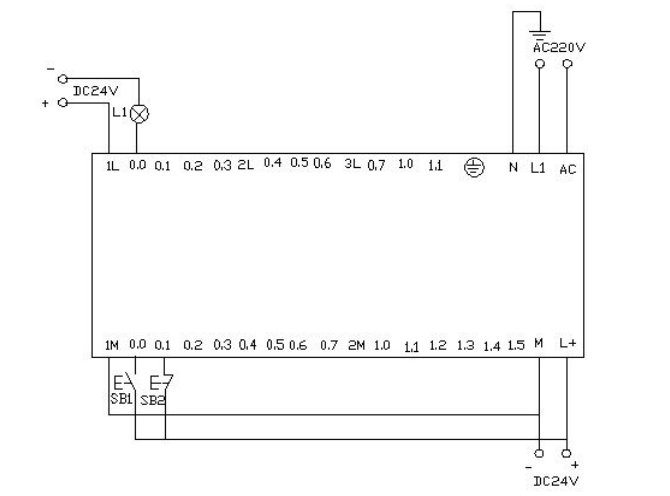
Download the written program to the Siemens S7-200 PLC for debugging, observe whether the results match the experimental requirements. Debug using the online control panel. When I0.0f (i.e., I0.0 is activated) is pressed, Q0.0 outputs, the light connected to Q0.0 will turn on, and at the same time, timer T37 starts timing. After one second, due to T37’s action, its normally closed contact opens, so Q0.0 has no output, and the connected light goes off. While the light is off, timer T38 starts, and after one second, the normally closed contact in series with timer T37 opens, so T37 resets, and its normally closed contact returns to normally closed. At this time, Q0.0 outputs again, and the connected light turns on.
Thus, the light connected to output Q0.0 turns on for one second and off for one second, flashing continuously until the I0.1f (i.e., I0.1 is activated) on the online control panel is pressed, at which point the flashing circuit stops working.
If you want to change the flashing frequency of the light, just change the timer’s time to achieve the desired effect.
➤PLC Wiring Diagram
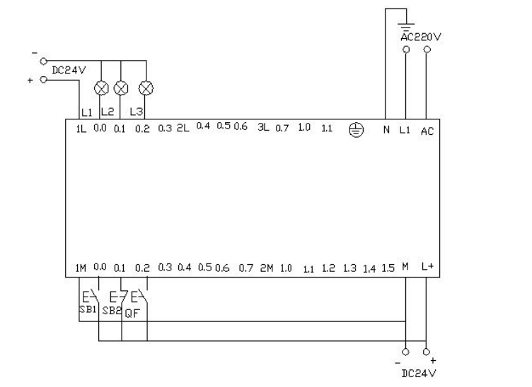
Download the written program to the Siemens S7-200 PLC for debugging. After downloading, we will open the online control panel for debugging and check whether the results meet the requirements.
First, set i0.2f on the control panel to indicate that the button is pressed, i.e., i0.2 is activated, indicating that circuit breaker QF is closed. When the start button i0.0f (SB2) is pressed, i.e., i0.0 is activated, the motor starts in star mode, Q0.0 and Q0.1 output, indicating that both lights L1 and L2 are on, while driving the timer. When the timer counts to 10 seconds, it switches to delta start, at which point Q0.1 has no output, and Q0.2 outputs, so both Q0.0 and Q0.2 output, and the motor runs in delta mode. The lights L1 and L3 on the wiring panel are on. When the I0.1f on the online panel is pressed (i.e., I0.1 is activated), the motor stops running. All output points will have no output.
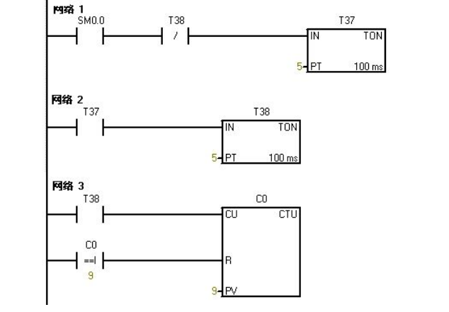
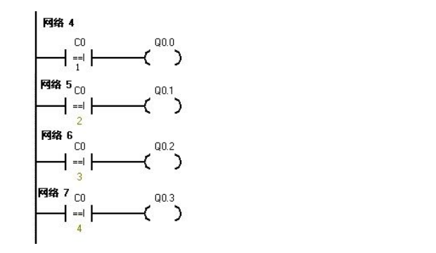
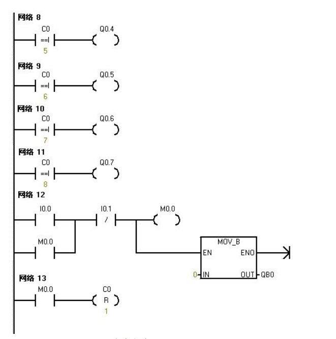
Use the eight outputs from PLC Q0.0 to Q0.7 to control eight color lights, making them turn on one by one every second and cycle. When I0.0 is activated, all lights turn off. When I0.1 is activated, the cycle starts again from Q0.0.
➤I/O Allocation Table

➤Ladder Diagram Program
➤PLC Wiring Diagram
Download the written program to the PLC for debugging; after downloading, we will open the online control panel for debugging to see if the results meet the requirements.
After powering on the PLC, sm0.0 remains activated. Therefore, t37 starts timing. After the delay, t38 starts timing; once t38’s timer reaches 5 seconds, its normally closed contact opens, causing t37 to stop timing, and t37’s normally open contact returns to normally open, so t38 stops timing. At this point, t38’s normally closed contact returns to normally closed, causing t37 to start timing again, and counter C0 starts counting once. This repeats. When the count is 1, Q0.0 is activated. When the counter reaches 2, Q0.1 is activated, and so on.
When the counter reaches 8, Q0.7 is activated. When the counter reaches 9, the counter C0 resets. When I0.0f (i.e., I0.0) is activated, the counter and Q0.0~Q0.7 all reset, meaning no lights are on. When I0.1f (i.e., I0.1) is activated, the counter starts counting again, and the lights turn on one by one from Q0.0.
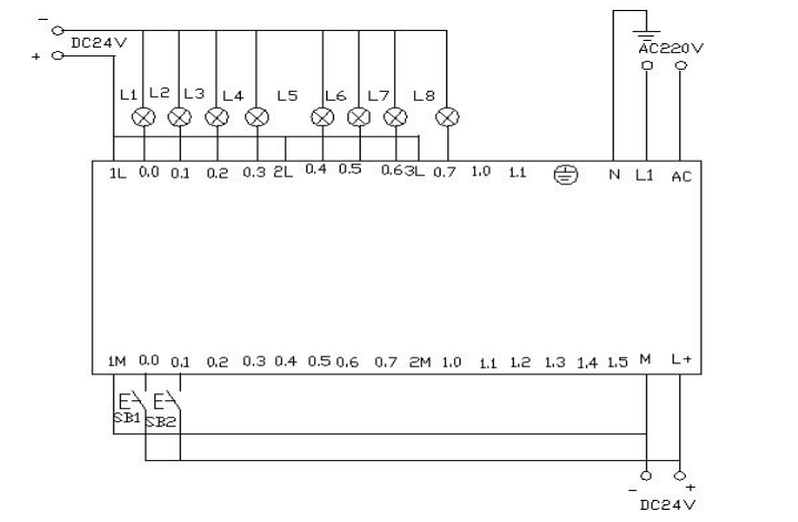
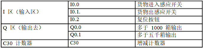
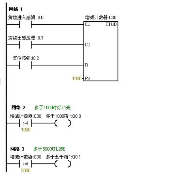
Record the goods entering and exiting the warehouse. The warehouse can hold a maximum of 6000 boxes of goods; if there are more than 1000 boxes, light L1 turns on, and if there are more than 5000 boxes, light L2 turns on.
➤I/O Allocation Table
➤Ladder Diagram Program
➤Program Debugging and Result Analysis
We set the light L1 to turn on when the value is 5. We set the light L2 to turn on when the value is 10. This way, we can see the experimental results faster.
When the online control panel button I0.0f is pressed (i.e., I0.0 is activated), it indicates that goods have entered. After clicking I0.0f on the online control panel five times, the counter value is 5 (indicating that there are 1000 boxes of goods in the warehouse), thus light L1 turns on, meaning Q0.0 outputs.
When I0.0f is clicked ten times, the counter value is 10 (indicating that there are 5000 boxes of goods), then light L2 also turns on, meaning Q0.1 outputs. When I0.0f is clicked continuously, the counter value continues to increase.
When I0.1f is pressed, the counter starts to decrease. Each click decreases the counter value by one. When the counter value is less than 10, it indicates that there are fewer than 5000 boxes of goods in the warehouse, and at this point, light L2 turns off (i.e., Q0.1 has no output). When I0.1f is clicked continuously and the counter value decreases to less than 5, it indicates that there are fewer than 1000 boxes of goods in the warehouse, and at this point, light L1 turns off, meaning Q0.0 has no output. When I0.2f is pressed, the counter resets. L1 and L2 turn off (i.e., Q0.0 and Q0.1 have no output).
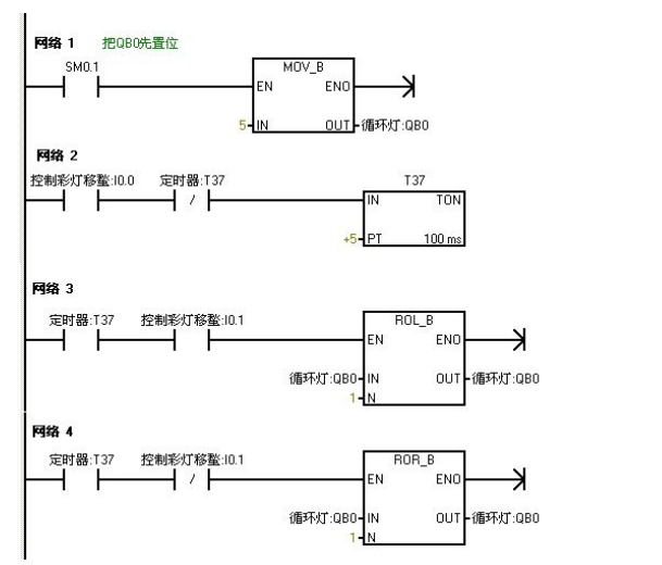
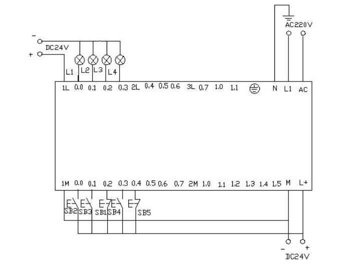
Use IO wires to control the eight color lights connected to Q0.0 to Q0.7 to shift in a loop, using t37 to time and shifting every 0.5 seconds. At the first scan, assign initial values to Q0.0 to Q0.7, allowing Q0.0 and Q0.2 to output first. Use I0.1 to control the direction of the color light shift.
➤I/O Allocation Table

➤Ladder Diagram Program
➤PLC Wiring Diagram
➤Program Debugging and Result Analysis
Download the program to the Siemens S7-200 PLC for debugging. When the PLC is powered on, Q0.0 and Q0.2 will output, thus lighting up Q0.0 and Q0.2.
When the button I0.0f (indicating that I0.0 has input) on the online panel is pressed, timer T37 starts timing, and every 0.5 seconds, the color lights shift right using Q0.0 and Q0.2 as the base. When the button I0.1f (indicating that I0.1 has input) on the online control panel is pressed, the color lights shift left in the same manner.
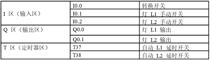
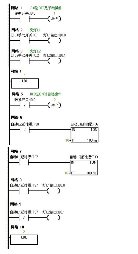
Use the jump instruction to control two lights L1 and L2, connected to Q0.0 and Q0.1, respectively, with switch positions I0.0 for control. The control switches for the two lights are I0.1 and I0.2. In manual mode, the two lights are controlled separately by their control switches. In automatic mode, the two lights alternate every second.
➤I/O Allocation Table
➤Ladder Diagram Program
➤Program Debugging and Result Analysis
➤I/O Allocation Table
➤Ladder Diagram Program
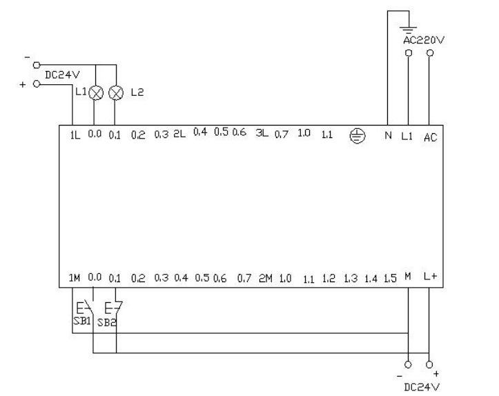
➤PLC Wiring Diagram
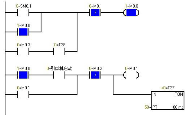
▲Program monitoring diagram when the PLC is powered on, blue indicates connection
➤Program Debugging and Result Analysis
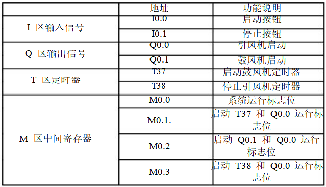
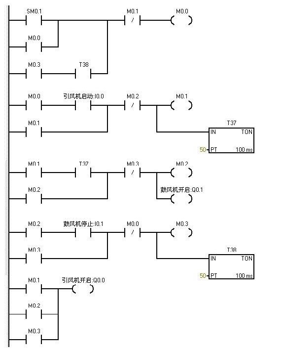
The characteristic of Sm0.1 is that it is activated during the first scanning cycle, and then it does not activate again. When the button I0.0f on the online control panel is pressed, I0.0 is activated, and Q0.0 outputs (i.e., the indicator light Q0.0 is on) and the inducer starts. At the same time, timer T37 is activated and starts timing, when timer T37 counts to 50 (i.e., indicator light Q0.1 is on) the blower starts. At this point, both fans are running.
When the button I0.1f on the online control panel is pressed, i.e. I0.1 is activated, the blower stops running (i.e., indicator light Q0.1 is off), and at the same time, timer T38 is activated and starts timing. After 5 seconds, the inducer stops running (i.e., indicator light Q0.0 is off).
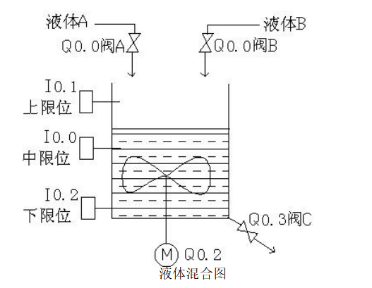
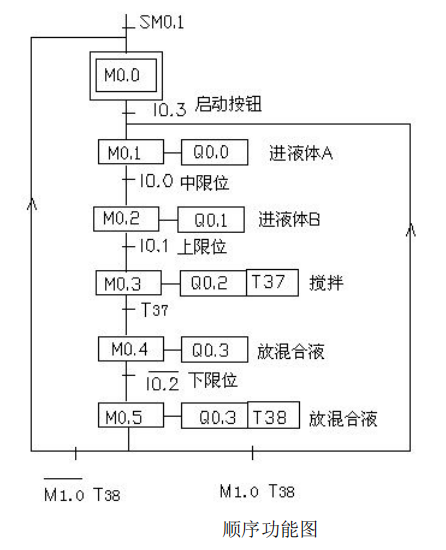
Use S7-200 to achieve automatic control of liquid mixing. When the start button is pressed, liquid valve A opens and liquid A flows into the mixer. When the liquid level reaches the middle limit, valve A closes, at the same time liquid valve B opens and liquid B flows into the mixer. When the liquid level reaches the upper limit, valve B closes, and at this point the motor starts to stir.
After stirring for one minute, the motor stops, and valve C opens, allowing the mixed liquid to flow out. When the liquid level reaches the lower limit, after 5 seconds, the container is emptied, and valve C closes. At the same time, valve A opens to inject liquid A. This cycle continues. If the stop button is pressed, the system must wait until a complete cycle is finished before stopping.

➤Ladder Diagram Program
➤PLC Wiring Diagram
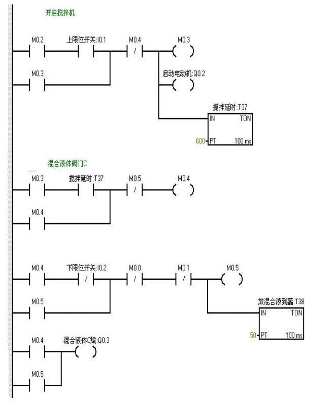
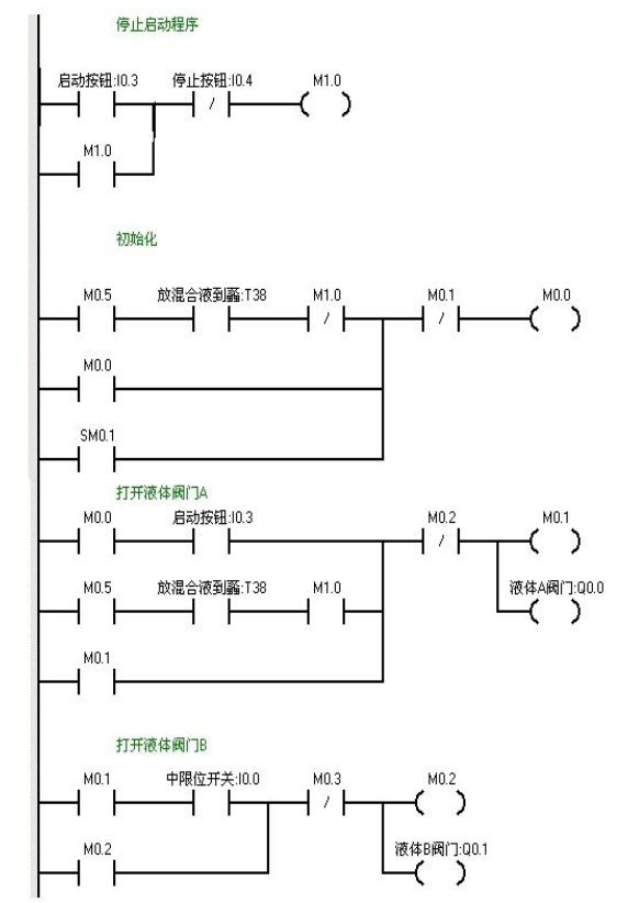
When the button I0.03f is pressed (i.e., I0.3 is closed), valve A opens (i.e., Q0.0 is on). When the button I0.0f (i.e., I0.0 middle limit is closed) is pressed, valve A closes, and valve B opens (i.e., Q0.0 is off, Q0.1 is on).
When the button I0.1f (i.e., upper limit I0.1 is closed) is pressed, valve B closes, and the motor starts, starting the stirring process (i.e., Q0.1 is off, Q0.2 is on). At this point, timer T37 starts timing for one minute. After one minute, the mixer stops stirring, and valve C opens (i.e., Q0.2 is off, Q0.3 is on). When the liquid level reaches the lower limit, valve C continues to open (i.e., Q0.3 is on), and timer T38 starts timing.
After 5 seconds, valve C closes, valve A opens (i.e., Q0.3 is off, Q0.0 is on), entering the next cycle. When the button I0.4f (indicating stop) is pressed, the system does not stop immediately but waits until a complete cycle is finished before stopping.
➤I/O Allocation Table
➤Ladder Diagram Program
➤Program Debugging and Result Analysis
When the button I0.03f is pressed (i.e., I0.3 is closed), valve A opens (i.e., Q0.0 is on). When the button I0.0f (i.e., I0.0 middle limit is closed) is pressed, valve A closes, and valve B opens (i.e., Q0.0 is off, Q0.1 is on).
When the button I0.1f (i.e., upper limit I0.1 is closed) is pressed, valve B closes, and the motor starts, starting the stirring process (i.e., Q0.1 is off, Q0.2 is on). At this point, timer T37 starts timing for one minute. After one minute, the mixer stops stirring, and valve C opens (i.e., Q0.2 is off, Q0.3 is on). When the liquid level reaches the lower limit, valve C continues to open (i.e., Q0.3 is on), and timer T38 starts timing.
After 5 seconds, valve C closes, valve A opens (i.e., Q0.3 is off, Q0.0 is on), entering the next cycle. When the button I0.4f (indicating stop) is pressed, the system does not stop immediately but waits until a complete cycle is finished before stopping.
➤Program Debugging and Result Analysis
When the button I0.03f is pressed (i.e., I0.3 is closed), valve A opens (i.e., Q0.0 is on). When the button I0.0f (i.e., I0.0 middle limit is closed) is pressed, valve A closes, and valve B opens (i.e., Q0.0 is off, Q0.1 is on).
When the button I0.1f (i.e., upper limit I0.1 is closed) is pressed, valve B closes, and the motor starts, starting the stirring process (i.e., Q0.1 is off, Q0.2 is on). At this point, timer T37 starts timing for one minute. After one minute, the mixer stops stirring, and valve C opens (i.e., Q0.2 is off, Q0.3 is on). When the liquid level reaches the lower limit, valve C continues to open (i.e., Q0.3 is on), and timer T38 starts timing.
After 5 seconds, valve C closes, valve A opens (i.e., Q0.3 is off, Q0.0 is on), entering the next cycle. When the button I0.4f (indicating stop) is pressed, the system does not stop immediately but waits until a complete cycle is finished before stopping.