Click the blue "Arm Selected" in the top left corner and select "Set as Favorite"Table of Contents
1. Why Use Cache?
When the ARM architecture was first developed, the clock speed of the processor was roughly similar to the memory access speed. Today’s processor cores are much more complex and can operate at clock frequencies several orders of magnitude faster. However, the frequency of external buses and storage devices has not reached the same level. Small on-chip SRAM blocks can be implemented to run at the same speed as the core, but this type of RAM is very expensive compared to standard DRAM blocks, which can be thousands of times larger in capacity. In many ARM-based systems, accessing external memory can take dozens or even hundreds of core cycles.
Cache is a small and fast memory block located between the core and main memory. It keeps copies of items in main memory. Accessing the cache is much faster than accessing main memory. Whenever the core reads or writes to a specific address, it first checks the cache. If it finds the address in the cache, it uses the data from the cache instead of accessing the main memory. This significantly improves the potential performance of the system by reducing the impact of slow external memory access times. It also lowers the system’s power consumption by avoiding the need to drive external signals.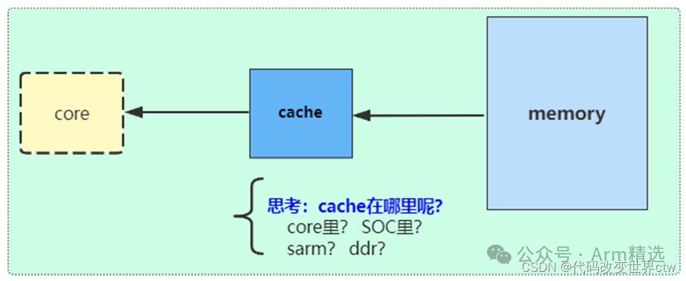
2. Background: Changes in Architecture?
-
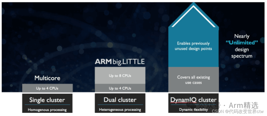
DynamIQ is a next-generation multi-core microarchitecture technology published by Arm in 2017, officially named DynamIQ big.LITTLE (hereinafter referred to as DynamIQ), replacing the long-used big.LITTLE technology.
-
The big.LITTLE technology divides multi-core processor IP into two clusters, each with a maximum of 4 cores, allowing for a total of 8 cores (4+4). In contrast, a DynamIQ cluster can support up to 8 cores.
-
In big.LITTLE, big and little cores must be placed in different clusters (e.g., 4 big + 4 little). In a DynamIQ cluster, big and little cores can coexist, achieving heterogeneous clusters, and can be configured flexibly, such as 1+3 or 1+7, which was not possible before.
-
In big.LITTLE, each cluster can only operate at one voltage, meaning that all cores within the same cluster have the same frequency. In DynamIQ, each CPU core can have different voltages and frequencies.
-
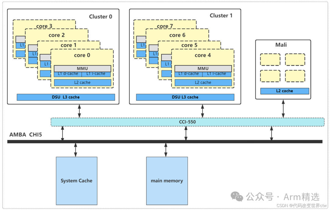
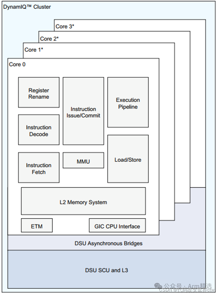
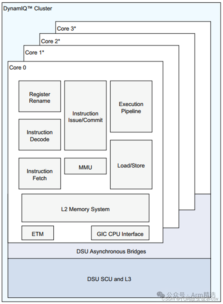
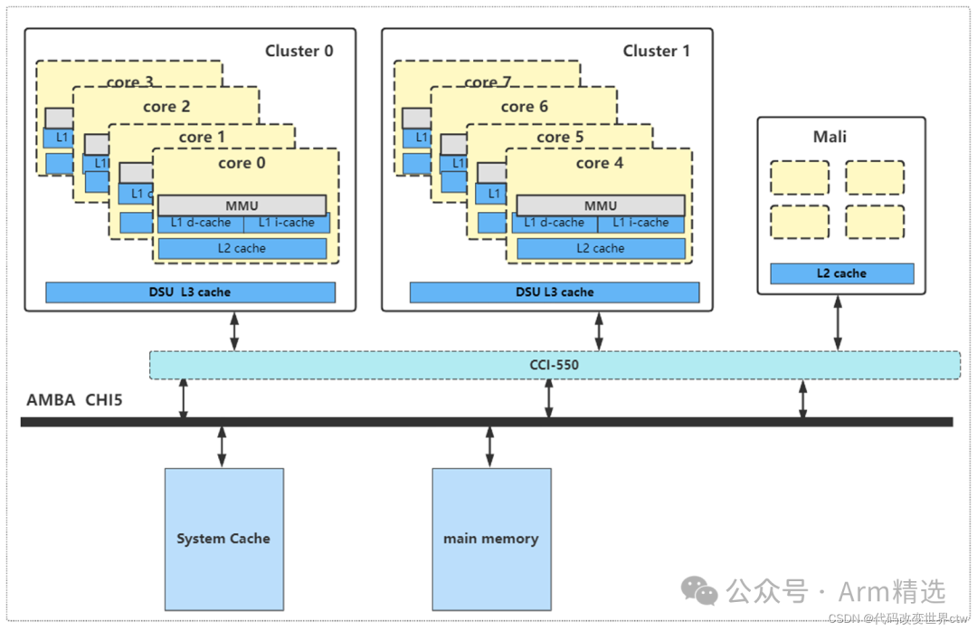
In big.LITTLE, the CPU cores in each cluster share the same L2 Cache, while in DynamIQ, each CPU core has its own L2 Cache while sharing the same L3 Cache. The sizes of L2 and L3 Cache are selectable, with dedicated L2 Cache ranging from 256KB to 512KB and shared L3 Cache ranging from 1MB to 4MB. This design significantly increases the speed of data exchange between cores. The L3 Cache is part of the DynamIQ Shared Unit (DSU).
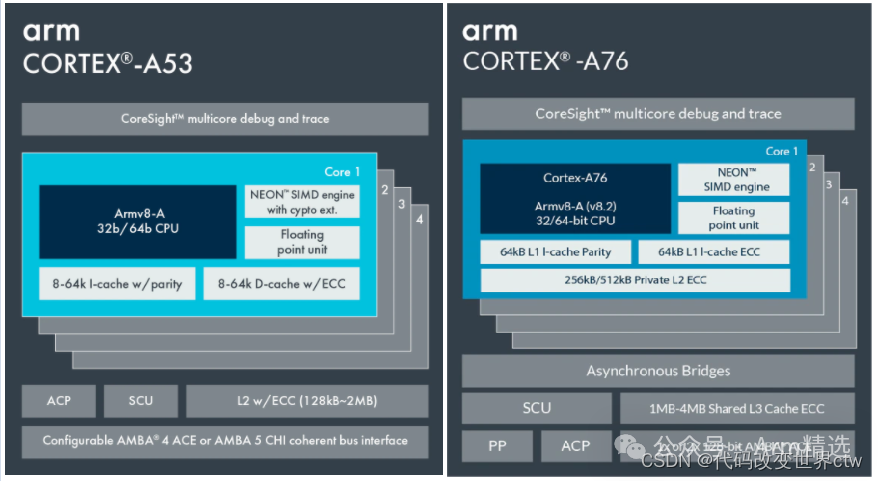
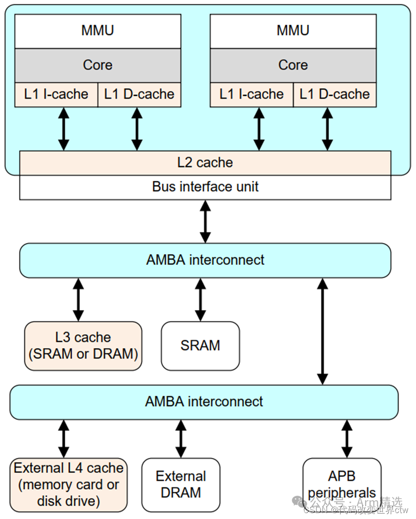
3. Cache Hierarchy – Big.LITTLE Architecture (Example: A53)
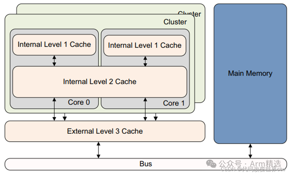
4. Cache Hierarchy – DynamIQ Architecture (Example: A76)
5. What Are the Sizes of L1/L2/L3 Cache?
Refer to ARM documentation; the cache size for each core is either fixed or configurable.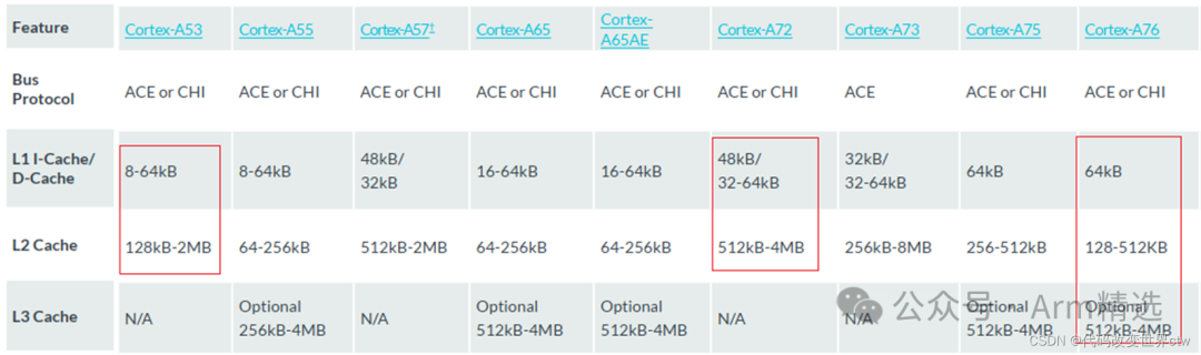
6. Introduction to Cache-Related Terminology
Consider: What are Set, Way, TAG, Index, Cache Line, Entry?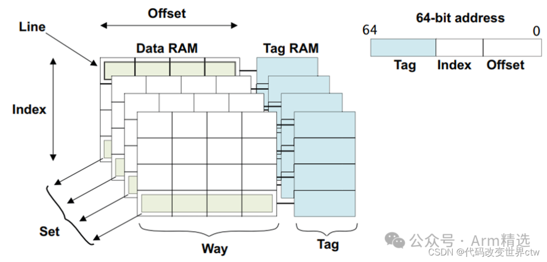
7. Cache Allocation Strategies (Allocation, Write-Through, Write-Back)
-
Read Allocation: When the CPU reads data and experiences a cache miss, a cache line is allocated to cache the data read from main memory. By default, caches support read allocation.
-
Write Allocation: When the CPU writes data and experiences a cache miss, write allocation strategies are considered. Without supporting write allocation, write instructions only update the main memory and stop there. When supporting write allocation, we first load data from main memory into the cache line (effectively performing a read allocation), then update the data in the cache line.
-
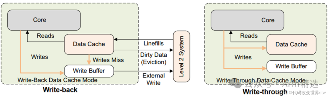
Write-Through: When the CPU executes a store instruction and hits the cache, we update the data in the cache and also update the data in main memory. The data in the cache and main memory remains consistent.
-
Write-Back: When the CPU executes a store instruction and hits the cache, we only update the data in the cache. Each cache line has a bit to indicate whether the data has been modified, known as the dirty bit. The dirty bit is set. The data in main memory is only updated when the cache line is replaced or explicitly cleaned. Thus, the data in main memory may be unmodified while the modified data resides in the cache, leading to potential inconsistency between cache and main memory.
8. Types of Memory in Architecture
9. Defined Cache Ranges in Architecture (Inner, Outer)
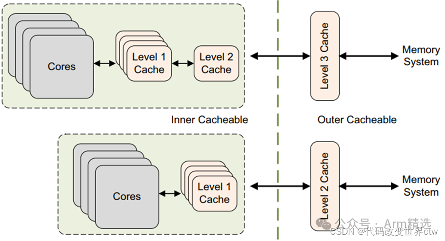
For cacheable attributes, inner and outer describe the definition or classification of the cache. For example, L1/L2 can be viewed as inner, while L3 can be viewed as outer.
Typically, integrated internal caches belong to inner cache, while caches on the external AMBA bus belong to outer cache. For example:
-
In the aforementioned big.LITTLE architecture (Example: A53), L1/L2 belong to inner cache, while if there is an L3 on the SoC, it belongs to outer cache.
-
In the aforementioned DynamIQ architecture (Example: A76), L1/L2/L3 belong to inner cache, while if there is a System cache (or other names) on the SoC, it belongs to outer cache.
We can configure attributes for each type of cache separately, such as:
-
Configuring inner Non-cacheable, Configuring inner Write-Through Cacheable, Configuring inner Write-back Cacheable.
-
Configuring outer Non-cacheable, Configuring outer Write-Through Cacheable, Configuring outer Write-back Cacheable.
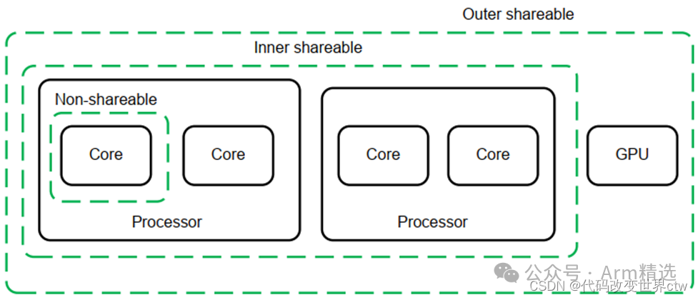
For the shareable attribute, inner and outer describe the range of the cache. For example, inner refers to the cache within the L1/L2 range, while outer refers to the cache within the L1/L2/L3 range.
Here’s a brief summary of Inner/Outer attributes:
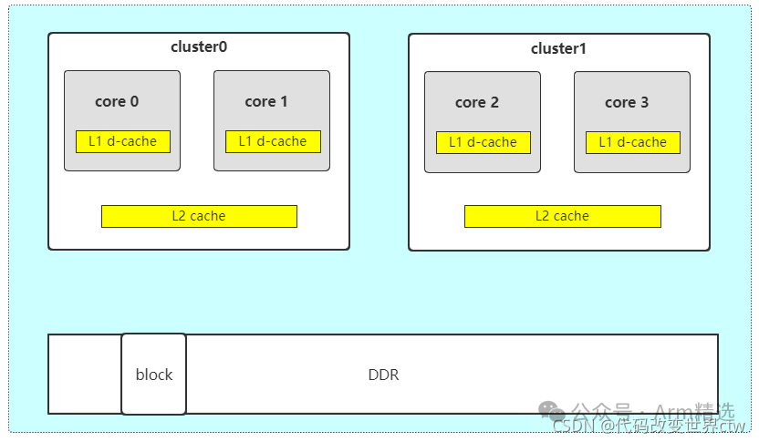
-
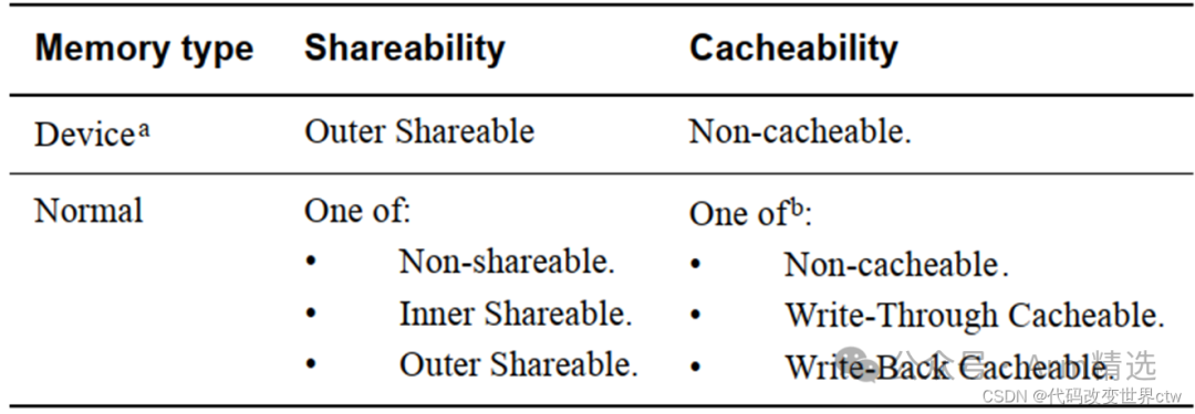
If the memory attribute of a block is configured as Non-cacheable, then the data will not be cached, ensuring that all observers see consistent memory, effectively making it Outer Shareable. The official documentation also states: In section B2.7.2, “Data accesses to memory locations are coherent for all observers in the system, and correspondingly are treated as being Outer Shareable.”
-
If the memory attribute of a block is configured as write-through cacheable or write-back cacheable, then the data will be cached.
-
If the memory attribute of a block is configured as non-shareable, then when core0 accesses that memory, the data will be cached in Core0’s L1 d-cache and cluster0’s L2 cache, but not in any other caches.
-
If the memory attribute of a block is configured as inner-shareable, then when core0 accesses that memory, the data will only be cached in core0 and core1’s L1 d-cache, and will also be cached in cluster0’s L2 cache, but not in any cache in cluster1.
-
If the memory attribute of a block is configured as outer-shareable, then when core0 accesses that memory, the data will be cached in all caches.
| Non-cacheable | Write-Through Cacheable | Write-Back Cacheable |
|---|---|---|
| Non-shareable | Data will not be cached. (For observers, this is effectively outer-shareable.) | When Core0 reads, data is cached in Core0’s L1 d-cache and cluster0’s L2 cache. If core0 and core1 have both read and written to that memory, and it is cached in both core0’s and core1’s L1 d-cache, then when core0 reads the data, core0’s L1 Dcache will update, but core1’s L1 Dcache will not update. |
| Inner-shareable | Data will not be cached. (For observers, this is effectively outer-shareable.) | When Core0 reads, data is cached in all caches of Cluster0. |
| Outer-shareable | Data will not be cached. (For observers, this is effectively outer-shareable.) | When Core0 reads, data is cached in all caches. |
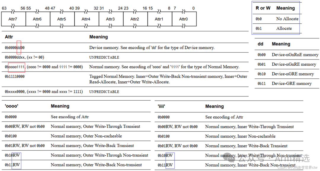
10. Types of Memory in Architecture (MAIR_ELx Register)
11. Types of Cache (VIVT, PIPT, VIPT)
MMU consists of TLB and Address Translation:
-
Translation Lookaside Buffer
-
Address Translation
 Cache can also be divided into:
-
PIPT
-
VIVT
-
VIPT

12. Inclusive and Exclusive Caches
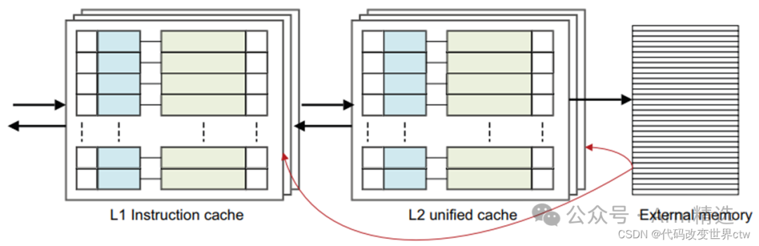 Let’s first discuss a simple memory read in a single-core setup. For example, LDR X0, [X1], where X1 points to main memory and is cacheable. (1) The core first checks the L1 cache for a read; if it hits, it directly returns the data to the core. (2) If it misses in L1, it checks the L2 cache; if it hits there, the data from L2 returns to the core, and this will cause the cache line to be replaced in L1. (3) If both L1 and L2 miss, the data will be read from memory, cached in both L1 and L2, and returned to the core.
Next, let’s look at a more complex multi-core system (not considering L3). (1) If it is an inclusive cache, the data will be cached in both L1 and L2. (2) If it is an exclusive cache, the data will only be cached in L1 and not in L2.
-
Strictly Inclusive: Any cache line present in an L1 cache will also be present in the L2.
-
Weakly Inclusive: Cache line will be allocated in L1 and L2 on a miss, but can later be evicted from L2.
-
Fully Exclusive: Any cache line present in an L1 cache will not be present in the L2.
13. Cache Query Process (Unofficial, Layman’s Terms)
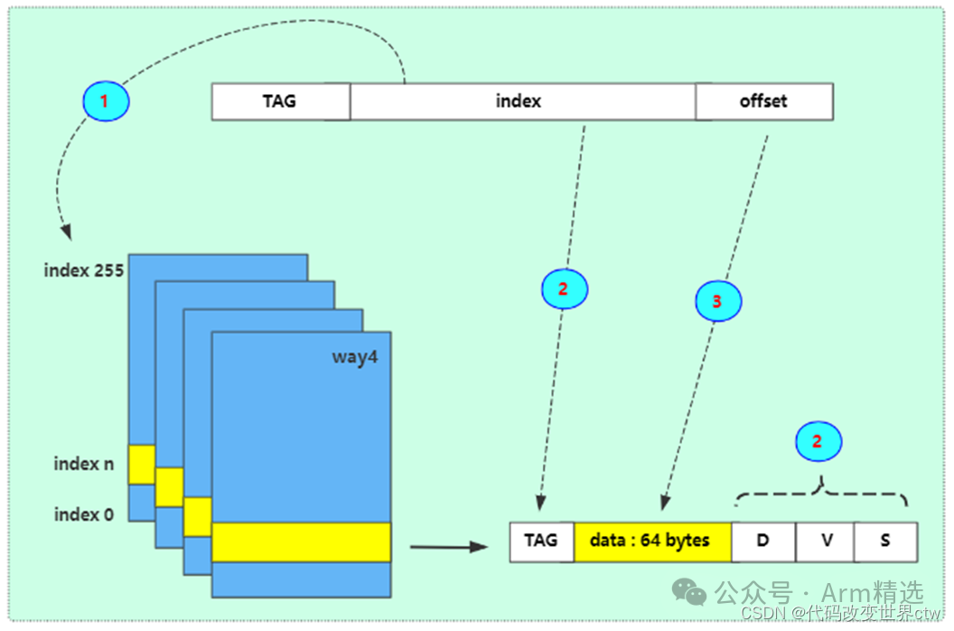 Assuming a 4-way set associative cache, size 64KB, cache line = 64bytes, then 1 way = 16KB, indexes = 16KB / 64bytes = 256 (Note: 0x4000 = 16KB, 0x40 = 64 bytes)
0x4000 – index 00x4040 – index 10x4080 – index 2…0x7fc0 – index 255
0x8000 – index 00x8040 – index 10x8080 – index 2…0xbfc0 – index 255
14. Cache Organization (Index, Way, Set)
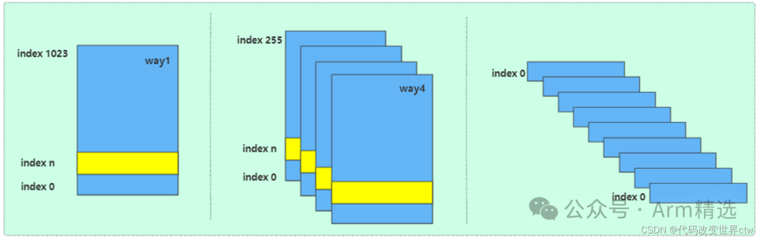
-
Fully Associative
-
Direct Mapped
-
4-Way Set Associative
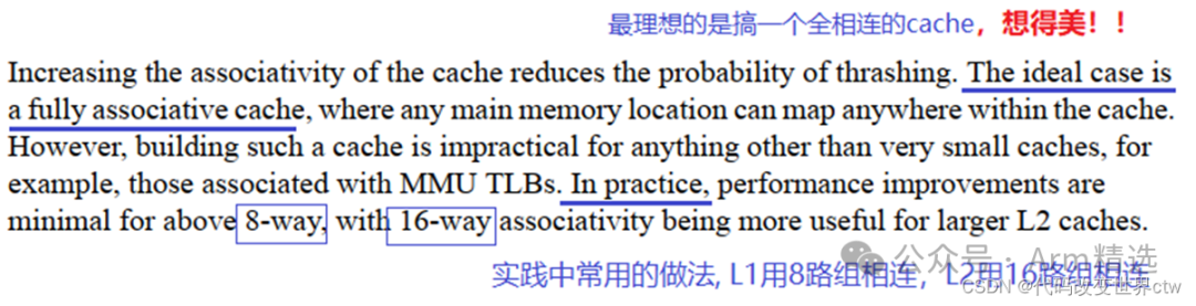
For example, A76
-
L1 i-cache: 64KB, 4-way 256 set associative, cache line is 64bytes.
-
L1 d-cache: 64KB, 4-way 256 set associative, cache line is 64bytes.
-
L2 cache: 8-way set associative cache, sizes selectable from 128KB, 256KB, or 512KB.
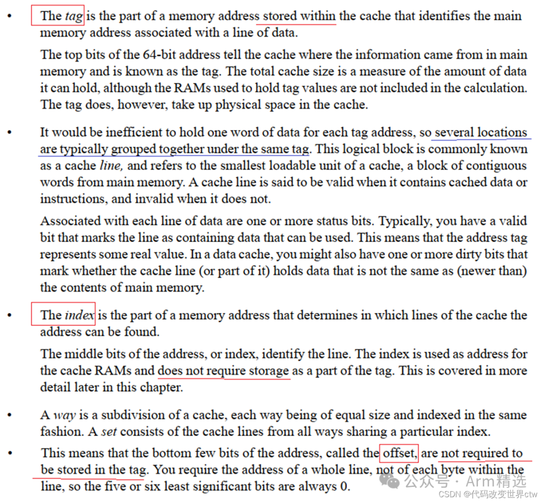
15. What’s Inside a Cache Line?

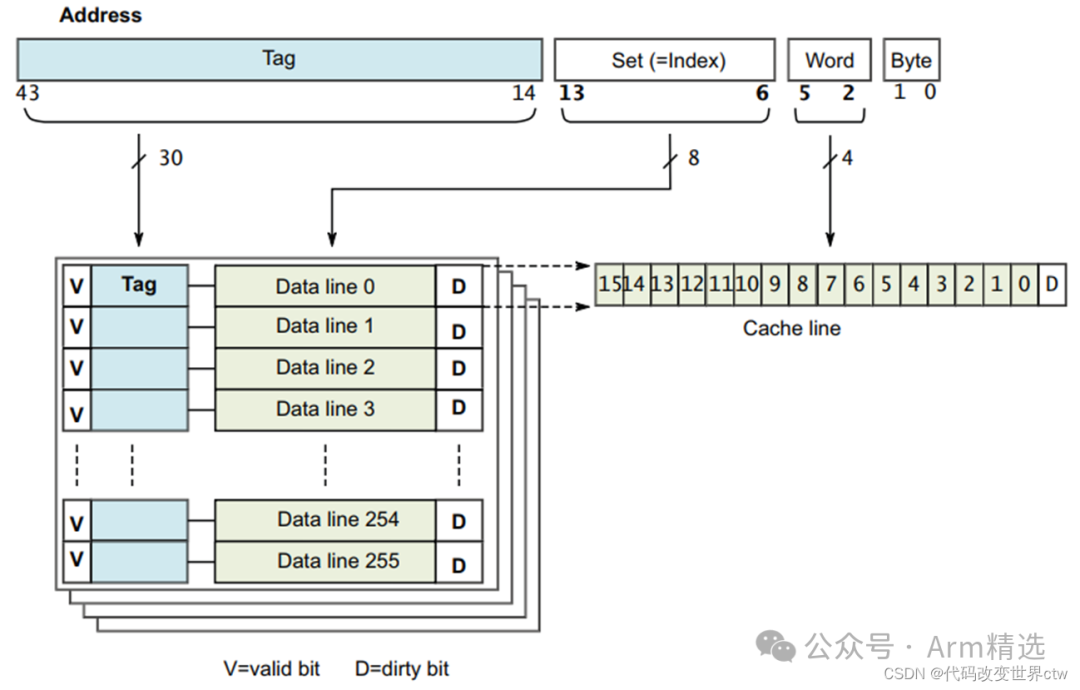
Each line in the cache includes: • A tag value from the associated Physical Address. • Valid bits to indicate whether the line exists in the cache, that is whether the tag is valid. Valid bits can also be state bits for MESI state if the cache is coherent across multiple cores. • Dirty data bits to indicate whether the data in the cache line is not coherent with external memory • data
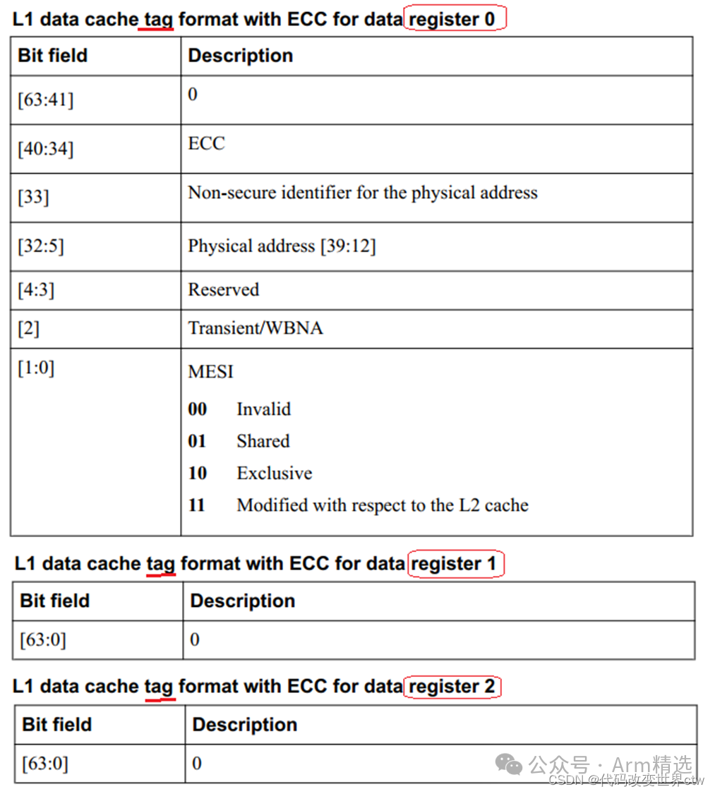
So what’s inside the TAG? (S13 will mention that the TAG here equals the TAG in the physical address) Below is an example showing what’s inside the TAG for A78:
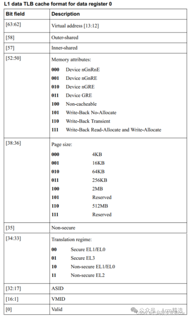
A little addition: What’s inside the TLB? Again, taking A78 as an example;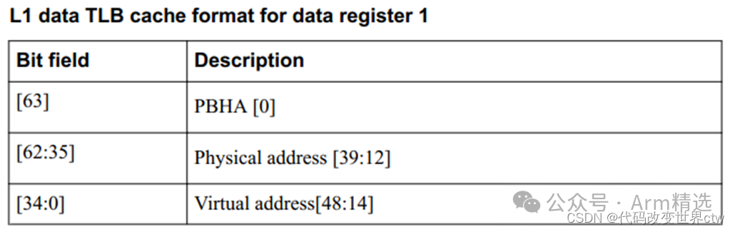
16. Cache Query Example
17. Principles of Cache Query
First, use the index to query the cache, then compare the TAG, checking the valid flag as well.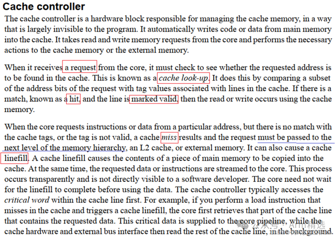
18. Cache Maintenance
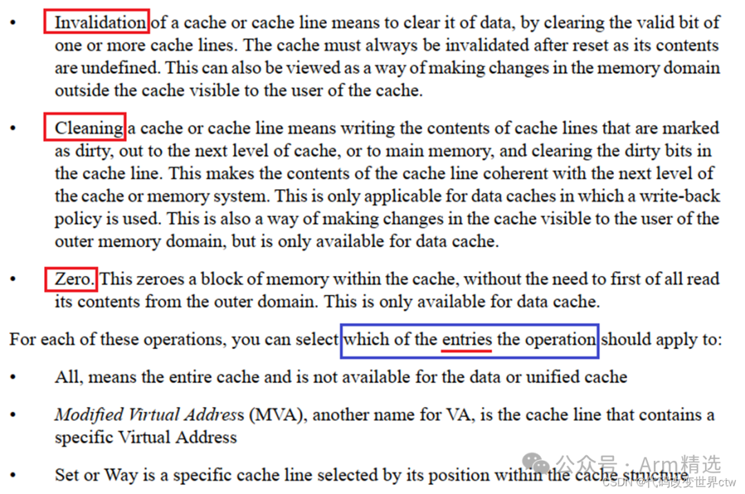 Software maintenance operations for cache have three types:
-
Invalidation: This modifies the valid bit, making the cache invalid, mainly for reads.
-
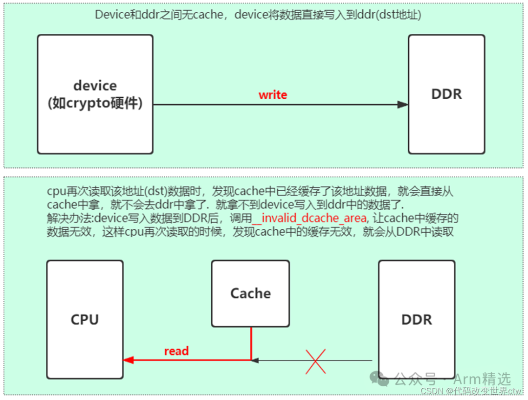
Cleaning: This is what we refer to as flush cache; it writes back the cache data to memory and clears the dirty flag.
-
Zero: This clears the data in the cache, which we refer to as clean cache.
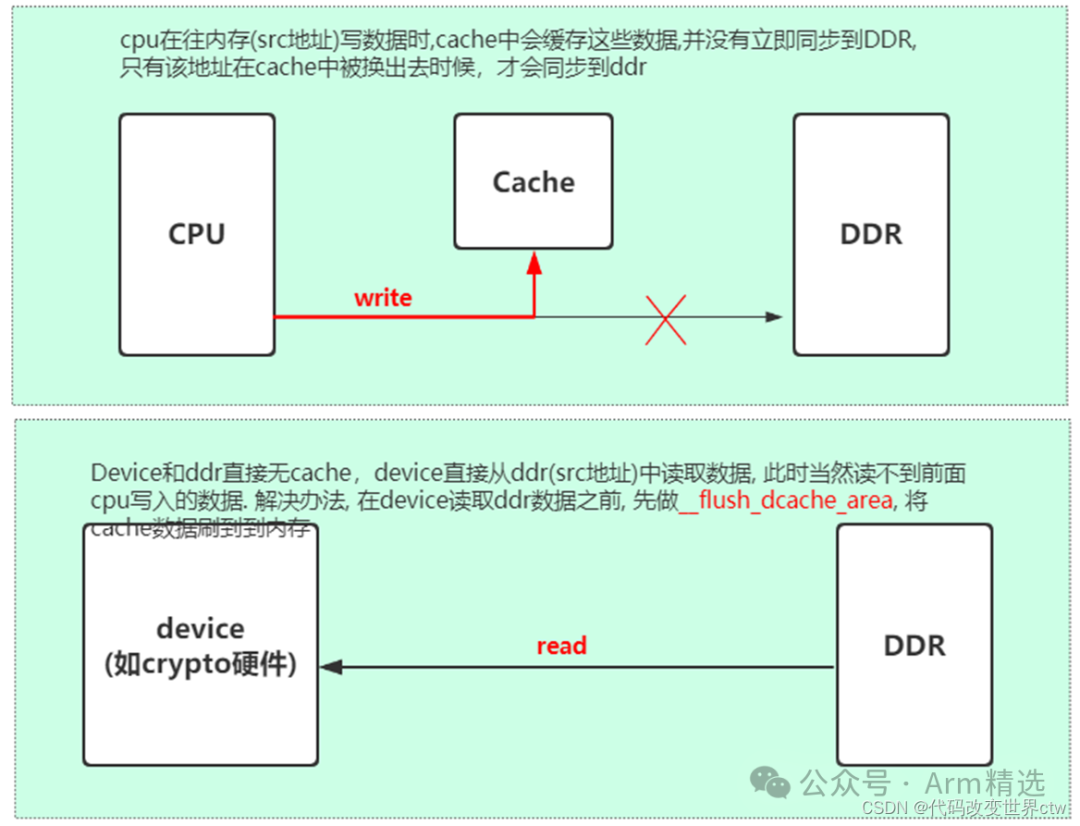
When is software maintenance of the cache needed? (1) When other masters change external memory, such as DMA operations. (2) When enabling or disabling the MMU for a whole region of memory access, such as enabling the MMU for REE and disabling it for TEE.
Regarding point (2), how does the cache relate to the MMU? This is because the enabling and disabling of the MMU affects memory permissions and cache policies.
19. Maintaining Memory Consistency in Software – Invalid Cache
20. Maintaining Memory Consistency in Software – Flush Cache
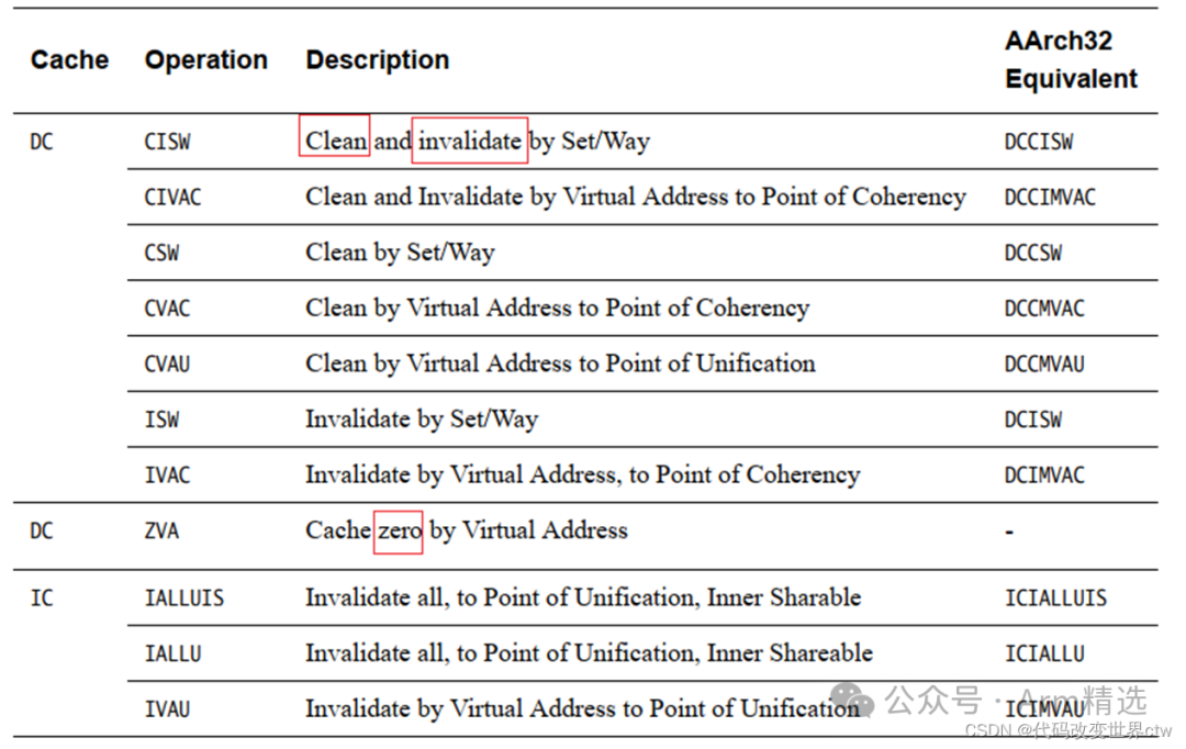
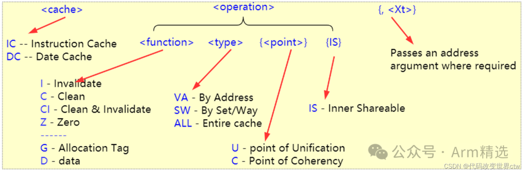
21. Introduction to Cache Consistency Instructions
<cache> <operation>{, <Xt>}
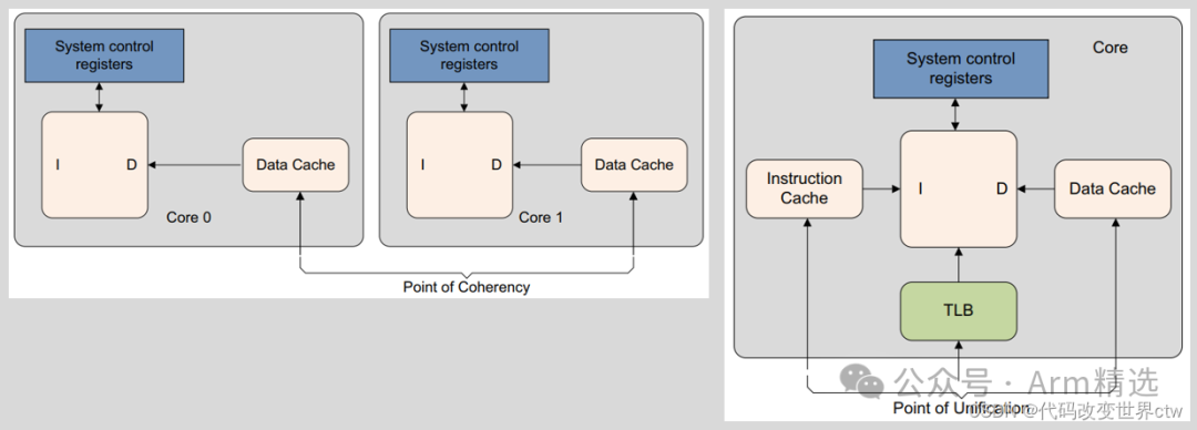
22. Introduction to PoC/PoU Points
-
PoC is the point at which all observers, such as cores, DSPs, or DMA engines, that can access memory, are guaranteed to see the same copy of a memory location.
-
PoU for a core is the point at which the instruction and data caches and translation table walks of the core are guaranteed to see the same copy of a memory location.
23. Summary of Cache Consistency Instructions
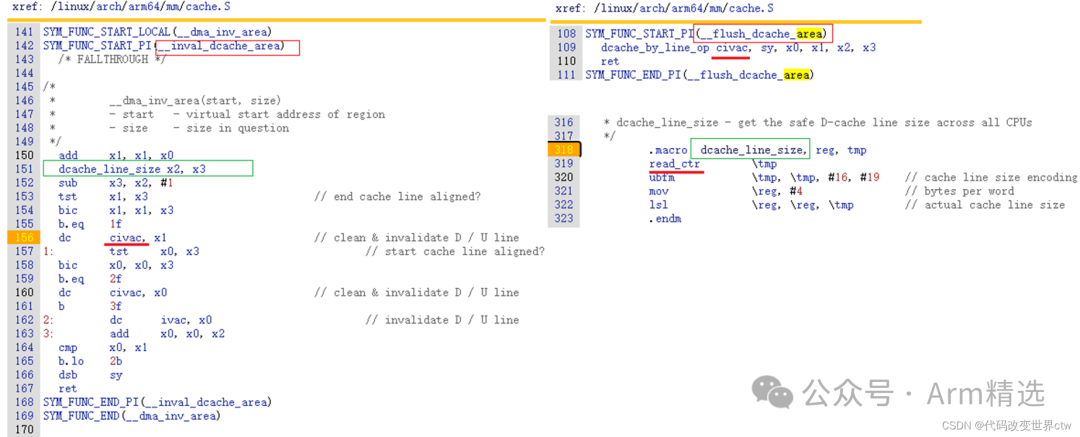
24. Examples of Using Cache Consistency Instructions in Kernel
25. Linux Kernel Cache API
linux/arch/arm64/mm/cache.S
linux/arch/arm64/include/asm/cacheflush.h

void __flush_icache_range(unsigned long start, unsigned long end);
int  invalidate_icache_range(unsigned long start, unsigned long end);
void __flush_dcache_area(void *addr, size_t len);
void __inval_dcache_area(void *addr, size_t len);
void __clean_dcache_area_poc(void *addr, size_t len);
void __clean_dcache_area_pop(void *addr, size_t len);
void __clean_dcache_area_pou(void *addr, size_t len);
long __flush_cache_user_range(unsigned long start, unsigned long end);
void sync_icache_aliases(void *kaddr, unsigned long len);
void flush_icache_range(unsigned long start, unsigned long end);
void __flush_icache_all(void)
26. Introduction to A76 Cache
A76
-
L1 i-cache: 64KB, 4-way 256 set associative, cache line is 64bytes.
-
L1 d-cache: 64KB, 4-way 256 set associative, cache line is 64bytes.
-
L2 cache: 8-way set associative cache, sizes selectable from 128KB, 256KB, or 512KB.
-
L1 TLB i-cache: 48 entries, fully associative, supports pages of 4KB, 16KB, 64KB, 2MB, and 32MB.
-
L1 TLB d-cache: 48 entries, fully associative, supports pages of 4KB, 16KB, 64KB, 2MB, and 512MB.
-
L2 TLB cache: 1280 entries, 5-way set associative.
-
L3 cache cache size options: 512KB, 1MB, 1.5MB, 2MB, or 4MB. cache line = 64bytes. 1.5MB cache is 12-way set associative; 512KB, 1MB, 2MB, and 4MB caches are 16-way set associative.
27. Introduction to A78 Cache
A78
-
L1 i-cache: 32 or 64KB, 4-way set associative, cache line is 64bytes, VIPT.
-
L1 d-cache: 32 or 64KB, 4-way set associative, cache line is 64bytes, VIPT.
-
L1 TLB i-cache: 32 entries, fully associative, supports pages of 4KB, 16KB, 64KB, 2MB, and 32MB.
-
L1 TLB d-cache: 32 entries, fully associative, supports pages of 4KB, 16KB, 64KB, 2MB, and 512MB.
-
L2 TLB cache: 1024 entries, 4-way set associative.
-
L3 cache cache size options: 512KB, 1MB, 1.5MB, 2MB, or 4MB. cache line = 64bytes. 1.5MB cache is 12-way set associative; 512KB, 1MB, 2MB, and 4MB caches are 16-way set associative.
28. System Registers Related to Cache in ARMv8/ARMv9
ID Register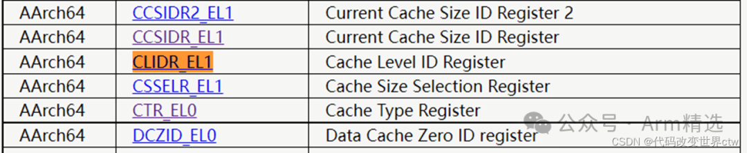 CTR_EL0, Cache Type Register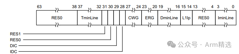
-
IminLine, bits [3:0] Log2 of the number of words in the smallest cache line of all the instruction caches that are controlled by the PE.
-
DminLine, bits [19:16] Log2 of the number of words in the smallest cache line of all the data caches and unified caches that are controlled by the PE.
29. Cache Consistency Between Cores
For Big.LITTLE architecture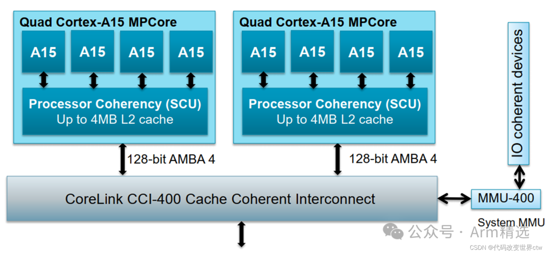
For DynamIQ architecture
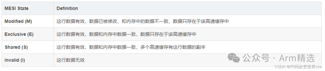
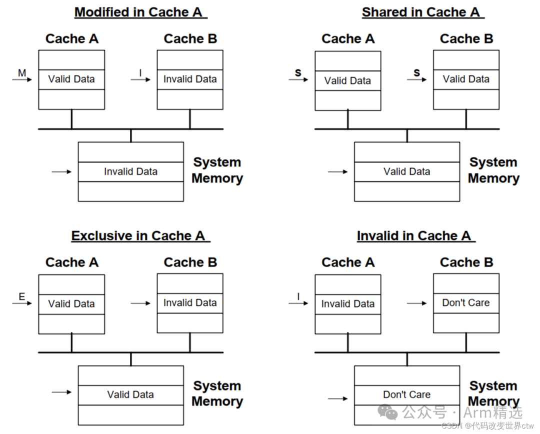
30. Introduction to MESI/MOESI
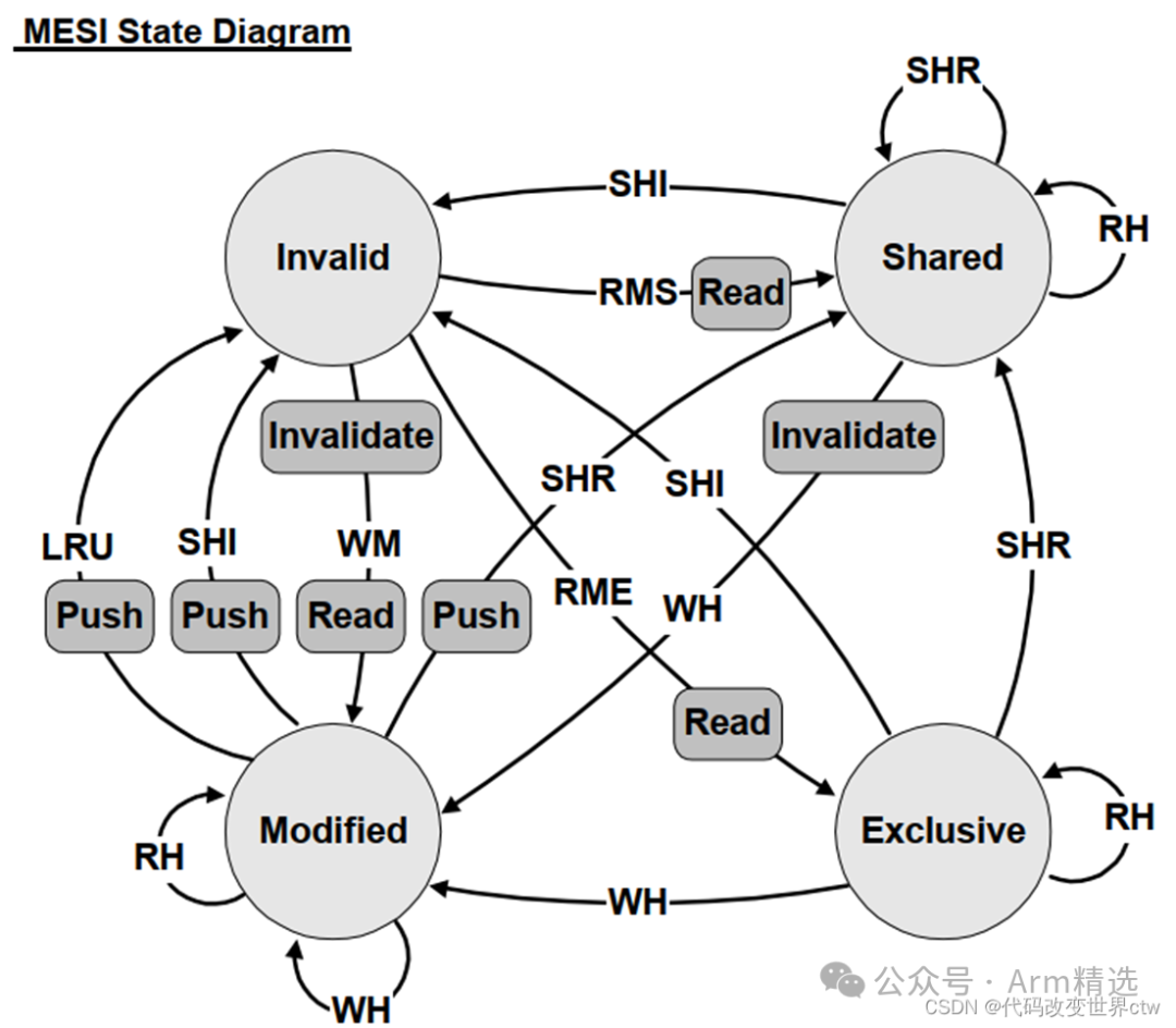 Events:
-
RH = Read Hit
-
RMS = Read miss, shared
-
RME = Read miss, exclusive
-
WH = Write hit
-
WM = Write miss
-
SHR = Snoop hit on read
-
SHI = Snoop hit on invalidate
-
LRU = LRU replacement
Bus Transactions:
-
Push = Write cache line back to memory
-
Invalidate = Broadcast invalidate
-
Read = Read cache line from memory

[Shop Address]

[Customer Service Consultation]