Table of Contents
1. Introduction to IGS
2. Main Functions of IGS
3. Sealing Methods of IGS
1. Introduction to IGS
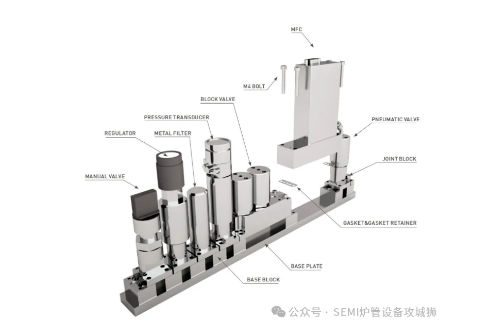
Many special gases used in FAB are toxic and corrosive, with high purity requirements, typically 5N or 6N. How can we ensure the safe and precise flow of these special gases into the process chamber? The answer lies in the use of IGS (Integrated Gas System). IGS consists of essential components such as valves (filters, diaphragm valves, pressure regulators, check valves, pneumatic valves, etc.), blocks, MFCs (mass flow controllers), and pressure transmitters.
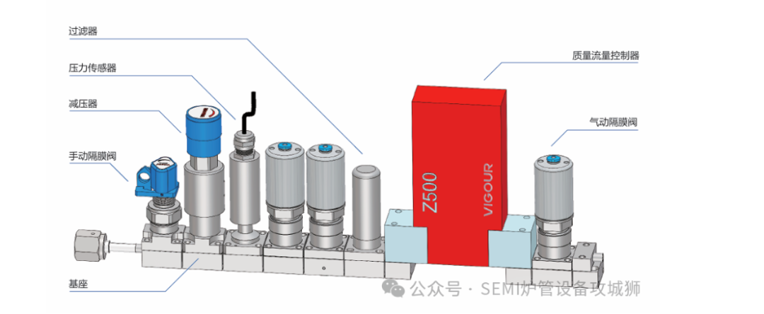
(IGS, Image Source: Internet)
2. Main Functions of IGS
1. Gas Flow Control: Change the gas flow direction through different configurations to meet the needs of various process steps.
2. Gas Filtration: Remove impurities and particles from the gas to ensure cleanliness, meeting the high purity gas requirements of semiconductor processes.
3. Pressure Regulation: Adjust the inlet and outlet pressure of the pipeline using pressure regulators to ensure stable gas supply during the process.
4. Flow Control: Precisely control gas flow using mass flow controllers (MFCs) to ensure stability and repeatability in the process.
5. Integrated Heating Module: Integrate heating components into a single module for easy installation and maintenance, while ensuring temperature control during gas delivery.
6. High Reliability and Sealing: Utilize sealing technologies such as W-seal and C-seal to ensure sealing performance in high vacuum and high-temperature environments, preventing gas leakage and impurities from entering the system.
3. Sealing Methods of IGS
IGS is classified into C-seal and W-seal based on the sealing method between the valve and the block, with C-seal being the mainstream, holding over 95% market share. Major suppliers include Swagelok, Compart, KiTz, and some domestic component manufacturers, while W-seal is primarily produced by some Japanese companies like Fujikin.
Both W and C seals are metal seals, with W-seal and C-seal gaskets made from 316L or 316L VAR stainless steel, suitable for ultra-high purity processes. The gaskets undergo electropolishing, with a surface roughness of Ra ≤ 0.13μm, meeting SEMI F19 UHP standards, and a sealing surface leakage rate of ≤ 1×10e-9 std·cm3/s.
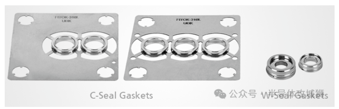
(C and W sealing gaskets, Image Source: WeChat Public Account: Semiconductor Engineer)
1. W-seal
The base of the W-seal is a floating structure. If there is a gap on one side after the lower surface of the valve body contacts the upper surface of the base, the floating base will automatically adjust when the screws are tightened, to some extent eliminating the gap and ensuring better contact of the sealing surface. The sealing mechanism is similar to a VCR joint, relying on the annular protrusion on the sealed component to compress the softer gasket. During installation, specialized tweezers can be used to ensure installation quality.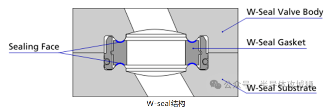
(Image Source: WeChat Public Account: Semiconductor Engineer)
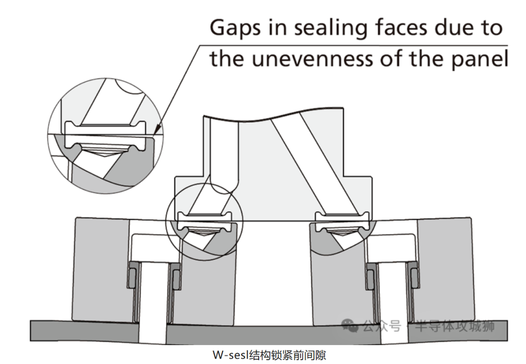
(Image Source: WeChat Public Account: Semiconductor Engineer)
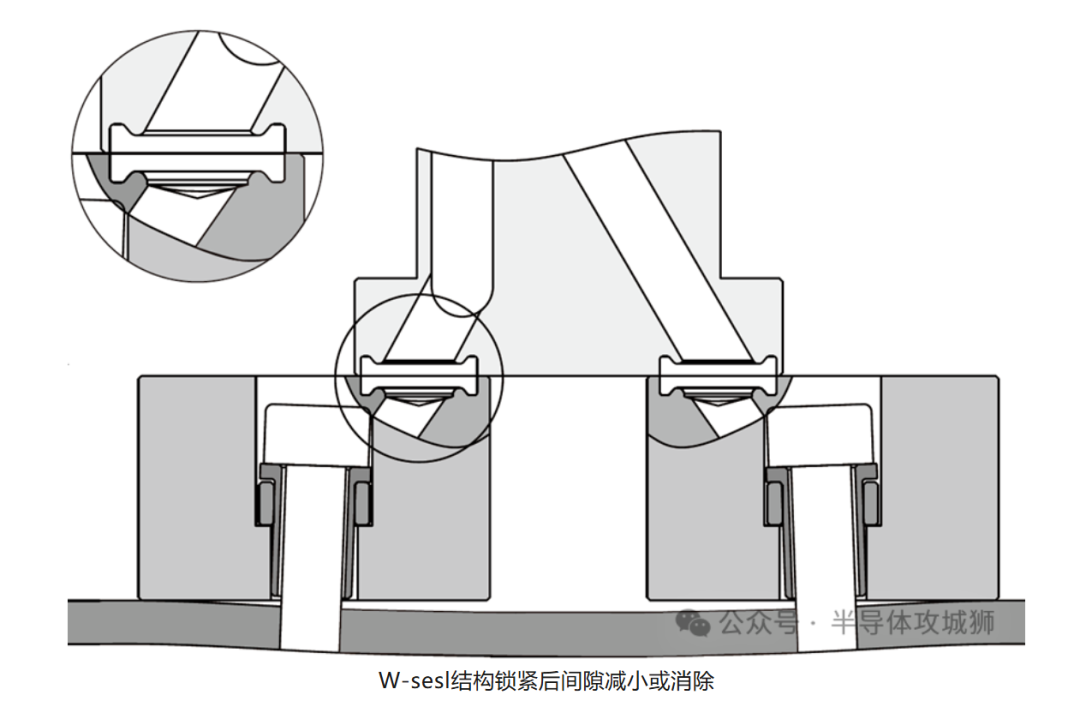
(Image Source: WeChat Public Account: Semiconductor Engineer)
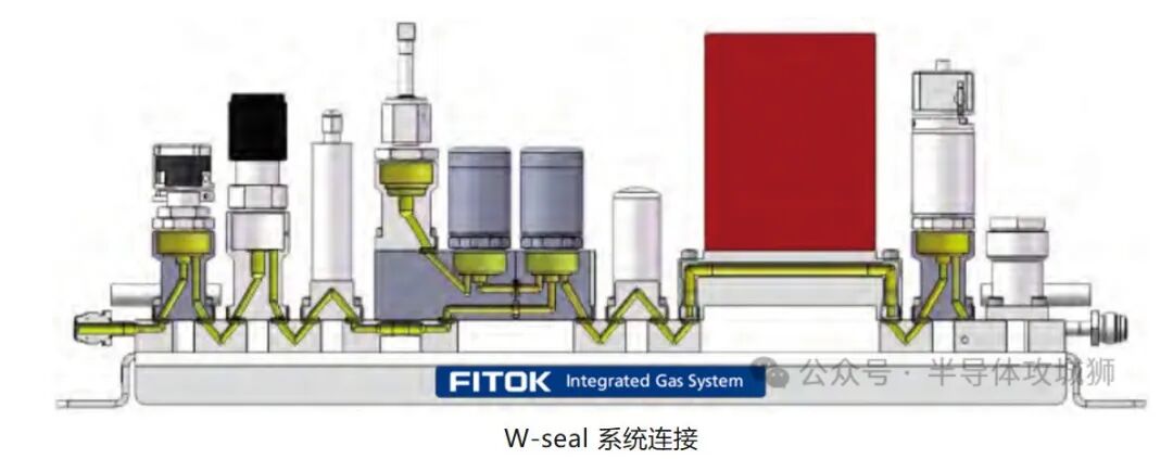
(Image Source: WeChat Public Account: Semiconductor Engineer)
2. C-seal
The C-seal gasket is shaped like the letter C, with flat protrusions at both ends (sealing surfaces). When properly installed, the upper and lower surfaces of the gasket contact the hardened surface of the valve body to form a seal. Additionally, the C-seal gasket’s bracket can help position multiple gaskets at once.
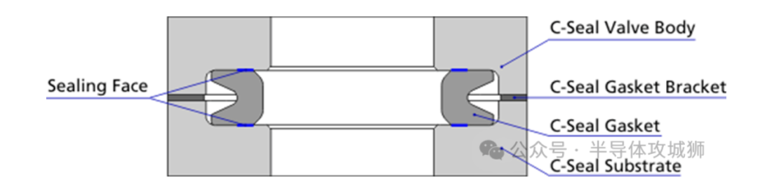
(C-seal structure, Image Source: WeChat Public Account: Semiconductor Engineer)
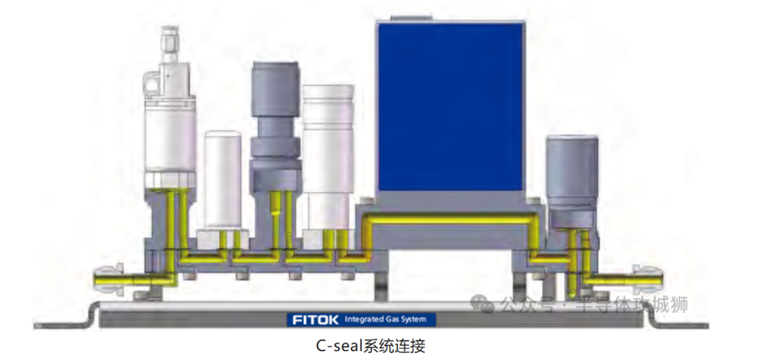
(Image Source: WeChat Public Account: Semiconductor Engineer)
Welcome to join the semiconductor equipment and process communication group~ Please add the editor and note your company + name + position.

Reference Article: Characteristics of W-seal and C-seal in IGS Gas Path Modules