For embedded developers, understanding assembly language and core registers is the foundation for a deeper understanding of the kernel. I never expected there would be so much content when I started writing, and I hope to convey many valuable insights. I would like to especially thank Teacher Wei Dongshan for his videos, which are absolutely full of useful information.-
1. ARM Core Registers
-
1.1 M3/M4 Core Registers
-
1.2 A7 Core Registers
-
1.3 The Value of PC Pointer in ARM
-
2. ARM Assembly Language
-
2.1 Basics of ARM Assembly
-
2.2 Assembly Pseudo Instructions
-
2.3 ARM Assembly Instruction Set
-
3. Code Disassembly Analysis
-
3.1 Disassembly with Different Compilers
-
3.2 Comparison Analysis of C and Assembly
Let’s start by looking at a few simple assembly instructions:
MOV R0, R1MOV PC, R14MOV instruction is used, but what are R0, R1, R14, and PC? Where do they come from? How are they used?|
|
|
|
|
|
|
|
|
|
|
|
|
|
|
|
|
|
|
|
|
|
|
|
1. ARM Core Registers
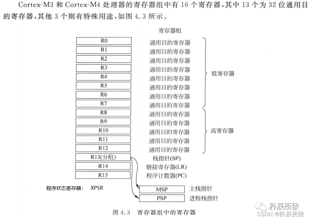
Cortex-M Registers, and here we will briefly explain again:1.1 M3/M4 Core Registers
-
R13 register stores the stack pointer, and the stack for M3/M4 grows downwards, meaning the address decreases when data is pushed onto the stack. -
The bare-metal program does not use PSP, only MSP, which is used when running RTOS. -
The stack is primarily manipulated using POP and PUSH instructions. When executing PUSH and POP operations, the SP address register is automatically adjusted.
-
LR is used to store the return address when calling a subroutine. For example, when using the BL (Branch with Link) instruction, LR’s value is automatically filled with the next instruction to execute after the function call, allowing for correct return and execution of the next instruction after the function exits. If another function is called within the function, LR will be overwritten, so it needs to be pushed onto the stack first.
-
It saves the return address of the subroutine. When using BL or BLX, the jump instruction automatically places the return address into r14; the subroutine returns by copying r14 to PC.
-
When an exception occurs, the r14 in exception mode is used to save the exception return address, allowing r14 to be pushed onto the stack to handle nested interrupts.
-
In Cortex-M3, the instruction has a 3-stage pipeline; for compatibility with Thumb code, reading PC returns the current instruction address + 4. -
The value returned when reading PC is the current instruction’s address + 4; the issue of PC values for M3, M4, and A7 needs to be explained separately.
1.2 A7 Core Registers
-
When reading PC, the returned value is the current instruction’s address + 8, and PC points to the addresses of the next two instructions. -
Since ARM instructions are always word-aligned, PC register bit[1:0] is always 00.
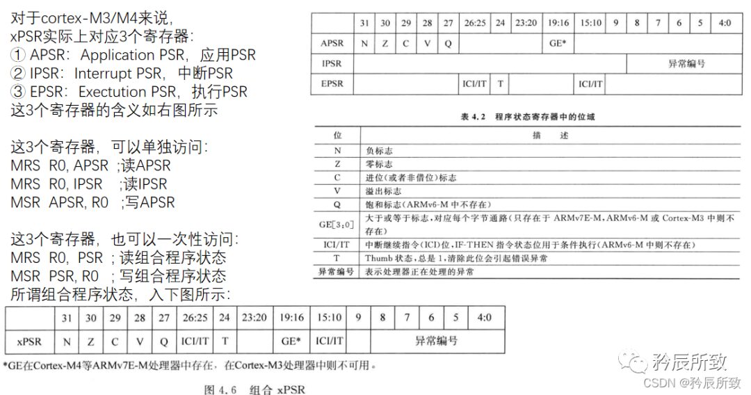
The program status register for the A7 core is CPSR: 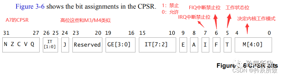
1.3 The Value of PC Pointer in ARM
Because ARM instructions use a three-stage pipeline mechanism, the value of the PC pointer is not the address value of the currently executing instruction:
-
The instruction at the current execution address A, -
Meanwhile, the next instruction is being decoded, -
And the instruction after that is being read: PC = A + 4 (Thumb/Thumb2 instruction set), PC = A + 8 (ARM instruction set)
In the document “ARM Architecture Reference Manual ARMv7-A and ARMv7-R edition”, there is a clear explanation of the PC value:  M3/M4/M0:
The value of PC = current address + 4;
Below is a disassembled program for STM32F103, where I found a segment of code with [pc, #0], making it easy to judge: 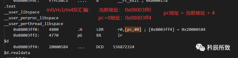
A7:
The value of PC = current address + 8; 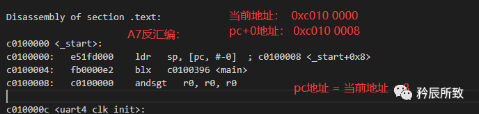
2. ARM Assembly Language
ARM chips belong to the Reduced Instruction Set Computing (RISC) architecture. The specific explanation has been mentioned in the summary of the following blog post:
Memory Management Related to STM32 (Memory Architecture, Memory Management, Map File Analysis)
2.1 Basics of ARM Assembly
2.1.1 ARM Instruction Set Description
Initially, ARM released two types of instruction sets:
-
The ARM instruction set, which is a 32-bit ARM instruction, occupies 32 bits per instruction, efficient but takes up too much space; -
The Thumb instruction set, which is a 16-bit Thumb instruction, occupies 16 bits per instruction, saving space;
For example: MOV R0, R1 can either be 16 bits or 32 bits.
So how do you switch between ARM instructions and Thumb instructions in assembly?
/*Switching between ARM and Thumb instructions*/

CODE16  ; (indicates that the following is a Thumb instruction)
...
...
; (calls the following function B)
bx  B_addr; (B's address B_addr's bit0 = 0 indicates a jump to execute ARM instructions)
;A function
...

CODE32  ; (indicates that the following is an ARM instruction)
...
...
;B function
; (return to the previous A function)
bx  A_addr + 1 ; (A's address A_addr's bit0 = 1 indicates a jump to execute Thumb instructions)
...

/**********************/
For A7, ARM7, and ARM9 cores, they support both 16-bit Thumb instruction set and 32-bit ARM instruction set.
For M3 and M4 cores, they support the Thumb2 instruction set, which allows mixed programming with 16-bit and 32-bit instructions.
For the core, whether to use the ARM instruction set or the Thumb instruction set is indicated in the XPSR and CPSR.
In M3/M4, the T (bit24) of the XPSR register indicates 1 for the Thumb instruction set. According to the above, M3 uses the Thumb2 instruction set, so T is always 1.
In A7, T (bit5) in CPSR indicates the instruction execution status, indicating whether the instruction is ARM or Thumb, usually together with J (bit24) to indicate the instruction type.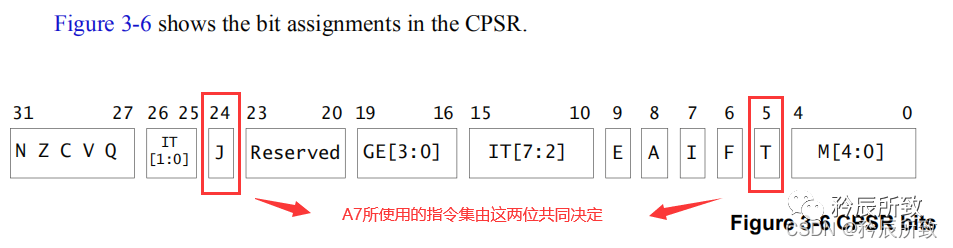
| J(bit24) | T(bit5) | Instruction Set |
|---|---|---|
| 0 | 0 | ARM |
| 0 | 1 | Thumb |
| 1 | 1 | ThumbEE — provides extensions from Thumb-2 that are particularly suitable for runtime code generation (e.g., just-in-time compilation). Thumb-2EE is designed for languages like Limbo, Java, C#, Perl, and Python, allowing real-time compilers to produce smaller code without sacrificing performance. |
| 1 | 0 | Jazelle |
Returning to the initial instruction MOV R0, R1
code 16  ; (indicates that the following instruction is a 16-bit Thumb instruction)
MOV R0, R1
code 32  ; (indicates that the following instruction is a 32-bit ARM instruction)
MOV R0, R1
Thumb    ; (the compiler will automatically identify whether it is a 32-bit or 16-bit Thumb2 instruction)
MOV R0, R1
2.1.2 ARM Assembly Format
Encoding Format:
The encoding formats of different instruction sets (taking LDR as an example) are excerpted from the “ARM Architecture Reference Manual ARMv7-A and ARMv7-R edition”:  For example, the UAL assembly format for “data processing” (other types include memory access, branch jumps, etc.) is:
  Operation indicates various assembly instructions, such as ADD, MOV; cond indicates the condition under which the instruction is executed, such as EQ, NE, etc.; S indicates whether the instruction will affect the value of the CPSR register; Rd is the destination register used to store the operation result; Rn is the first operand register; Operand2 is the second operand, which can have three sources: 1– immediate value, 2– register, 3– register shifted.
The instruction encoding format is as follows (32 bits):|bit 31-28 |27-25 |24-21 |20 |19-16 | 15-12 |11-0 |
|–|–|–|–|–|–|–|–|–|
|cond | 001 |Operation |S |Rn |Rd | Operand2 |
For example:
...
CMP R0, R2      ; Compare the values of R0 and R2
MOV EQ R0, R1  ; Add EQ, if the values of R0 and R2 are equal, then execute this statement
...
For the Operation in the “data processing” instructions, the instruction set is as follows: 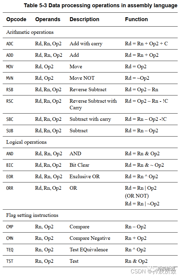 For the conditions cond, see below:
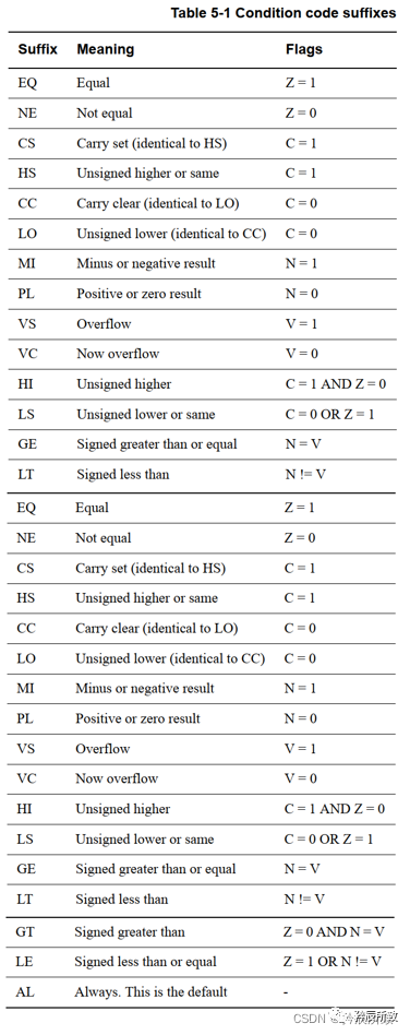
2.1.3 Immediate Values
In an ARM data processing instruction, in addition to including the data value to be processed, it must also indicate the ARM command name, control bits, registers, and other information. Therefore, the number of bits used to represent the data value to be processed in an ARM data processing instruction can only be less than 32 bits;
In the above ARM assembly format, we mentioned that ARM sets in the instruction format that only the low 12 bits of the instruction machine code can be used to represent the constant to be operated on. 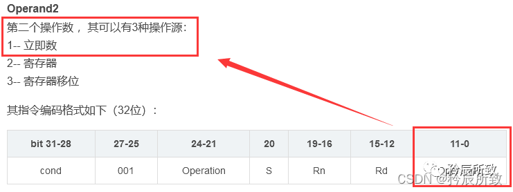
So for the instruction MOV R0, #value (store the value in R0 register), the value of value cannot be arbitrary; it must meet certain conditions. In the official document, the value must meet the following conditions: 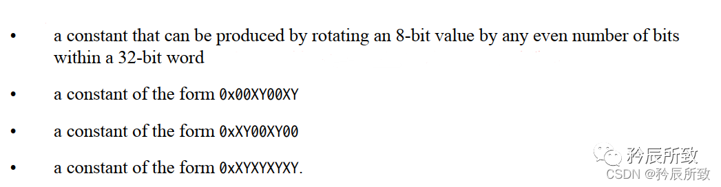 What is an Immediate Value?
The numbers that meet the conditions in the above image are called immediate values, which are numbers that conform to certain rules.
Immediate values are represented as follows: Each immediate value is obtained by rotating an 8-bit constant to the right by an even number of bits. The number of bits rotated is represented by a 4-bit binary multiplied by two.
Immediate Value = An 8-bit constant rotated by an even number of bits
An 8-bit constant rotated right (Y*2 = {0,2,4,6,8, …,26, 28, 30}) will yield an immediate value;(Why is it from 0 to 30 for even numbers explained below)
If you want to understand immediate values more deeply, I recommend a blog post: Deep Understanding –>> Immediate Values
ARM processors handle data in 32-bit units, and to extend to 32 bits, a construction method is used, whereby in the 12 bits, 8 bits represent the basic data value and 4 bits represent the shift value. By rotating the 8-bit basic data value to the right by the shift value * 2, the constant to be operated on can be represented.
It is important to emphasize that the final number of rotations is determined by the 4-bit shift value multiplied by 2, so the final number of rotations must be an even number. Why multiply by 2? Essentially, it is due to insufficient range; a 4-bit representation of the shift value can only indicate a maximum of 15 rotations (a shift of 0 means no rotation). Adding the 8-bit data is still not enough for 32 bits, so the internal structure of the ALU is designed to multiply the 4-bit shift value by 2, allowing the 12 bits to represent a 32-bit constant.
Therefore, the 12-bit data storage format is as follows: |bit 11-8 |7-0 |
|–|–|–|–|–|–|–|–|–|
|Shift 1111b (0~15) | 8-bit constant |
However, determining whether a number is an immediate value is quite cumbersome. So how can we assign any value to the R0 register? This is where pseudo instructions come into play, and next, we will discuss what pseudo instructions are.
2.2 Assembly Pseudo Instructions
Assembly language is divided into two parts: the standard instruction set and the non-standard instruction set. Pseudo instructions belong to the non-standard instruction set.
What are Pseudo Instructions?
They are similar to macros, allowing complex operations that require multiple instructions to be completed through new label definitions. This is what pseudo instructions do.
They are similar to preprocessing in C language, where during preprocessing, a set of macros is defined and transformed into actual C language code. Similarly, pseudo instructions are defined and then assembled, translating into standard assembly instructions. A simple pseudo instruction may translate into many standard assembly instructions, which is the most important function of pseudo instructions.
The CODE16 CODE32 mentioned earlier are also pseudo instructions used to specify the format of the following code.
What is the Function of Pseudo Instructions?
Basic instructions can perform various operations, but they can be too cumbersome. Pseudo instructions define some parameterized macros that can better implement the logic of assembly programs. (For example, if I want to set a value to register R0, but later I modify register R0 and need to read the previous value again, I would need to temporarily save the value to SPSR, CPSR, and keep switching.)
Pseudo instructions only work before the assembler; once assembled, they translate into standard assembly instructions.
The categories of pseudo instructions can be divided into ARM assembly pseudo instructions and GNU assembly pseudo instructions.
ARM assembly pseudo instructions are from ARM, while GNU assembly pseudo instructions are from the GNU platform. They have their own assemblers, and the syntax explanations for different assemblers can be set differently.
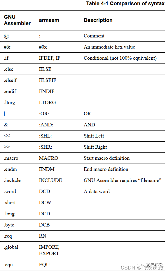
2.2.1 GNU Assembly Pseudo Instructions
Here are some pseudo instructions and explanations. For specific pseudo instructions, you can analyze them along with ARM assembly pseudo instructions:
| bit 11-8 | 7-0 |
|---|---|
| .word | Allocate a 4-byte space |
| .byte | Define single-byte data |
| .short | Define double-byte data |
| .long | Define a 4-byte data |
| .equ | Assignment statement: .equ a, 0x11 |
| .align | Data byte alignment: .align 4 (4-byte alignment) |
| .global | Define global symbol: .global Default_Handler |
| .end | End of source file |
2.2.2 ARM Assembly Pseudo Instructions
In another blog post of mine: The Startup Process of STM32 (Analysis of startup_xxxx.s file)
Some explanations of pseudo instructions have been provided there, and here are some parts of the explanation:
AREA:
Used to define a code segment or data segment. The attribute field indicates the related attributes of the code segment (or data segment), with multiple attributes separated by commas. 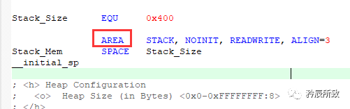 If the segment name starts with a digit, it must be enclosed in ” | “:
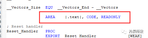
ALIGN:
ALIGN pseudo instruction can align the current position to meet certain alignment requirements by adding padding bytes. The value of the expression is used to specify the alignment, with possible values being powers of 2, such as 1, 2, 4, 8, 16, etc. 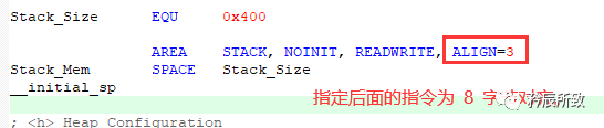 If no expression is specified, the current position will be aligned to the next word’s position.
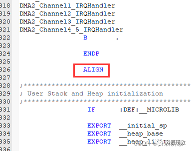
CODE16 and CODE32:
Specify whether the following instructions are ARM instructions or Thumb instructions, as mentioned earlier.
ENTRY:
Used to specify the entry point of the assembly program. In a complete assembly program, there must be at least one ENTRY (there can be multiple, but when there are multiple, the actual entry point of the program is specified by the linker), but in a source file, there can be at most one ENTRY.
In startup_stm32f103xg.s, there is none.
END:
Used to inform the compiler that it has reached the end of the source program. 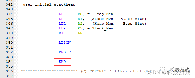 IMPORT and EXPORT:
IMPORT defines that this is a label for an external variable not defined in this program. EXPORT indicates that the variable used in this program is provided for other modules to call. 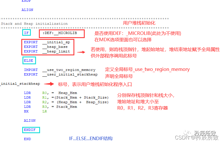
2.2.3 LDR and ADR
LDR Pseudo Instruction:
Having briefly introduced the basics of pseudo instructions, returning to the question left in the previous section: how do we copy any value to R0? We use the pseudo instruction: LDR R0, =value
The compiler will replace the “pseudo instruction” with the actual instruction:
LDR R0, =0x12 0x12 is an immediate value, so it is replaced with: MOV R0, #0x12
LDR R0, =0x12345678 0x12345678 is not an immediate value, so it is replaced with: LDR R0, [PC, #offset] // 2. Use Load Register to read memory instruction to read the value, offset is determined at link time.
……Label DCD 0x12345678 // 1. The compiler saves this value somewhere in the program
ADR Pseudo Instruction:
ADR means address, used to read the address of a certain label: ADR{cond} Rd, label
ADR  R0,  Loop
...
Loop
    ADD  R0, R0, #1

    ;(It is a "pseudo instruction" that will be converted into a real instruction, such as:)
ADD R0, PC, #val   ; the address of loop equals the current PC value plus or minus the value of val, the value of val is determined at link time,
...
Loop
    ADD  R0, R0, #1
2.3 ARM Assembly Instruction Set
In the article “Authoritative Guide to ARM Cortex-M3 and Cortex-M4”, there is a detailed description of the instruction set in Chapter 5: 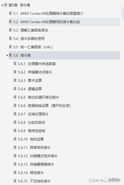 Assembly instructions can be divided into several categories: data processing, memory access, jumps, saturation operations, and other instructions.
Data Transfer Command MOV
The MOV instruction is used to copy data from one register to another or to transfer an immediate value to a register.
The format of the MOV instruction is: MOV{condition}{S} destination register, source operand
MOV R0, R1     ;@ Transfer data from register R1 to R0, i.e., R0=R1
MOV R0, #0X12  ;@ Transfer immediate value 0X12 to R0 register, i.e., R0=0X12
Status Register Access MRS and MSR
The MRS instruction is used to transfer data from special registers (such as CPSR and SPSR) to general-purpose registers.
The MSR instruction, conversely, is used to transfer data from general-purpose registers to special registers.
;M3/M4
MRS  R0, APSR  ; Read APSR separately
MRS  R0,  PSR  ; Read combined program status

;A7
MRS  R0, CPSR  ; Read combined program status

...
MSR CPSR,R0   ; Transfer the content of R0 to CPSR
Memory Access LDR and STR
LDR:
LDR instruction is used to transfer a 32-bit word data from memory to the destination register. This instruction is typically used to read 32-bit word data from memory into a general-purpose register, followed by data processing.
The format of the instruction is: LDR{condition} destination register, <memory address>
When the program counter PC is used as the destination register, the data read from memory is treated as the destination address, allowing for program flow jumps.
LDRB: byte operation
LDRH: half-word operation
LDR Rd, [Rn , #offset] ; Read data from memory at Rn+offset into Rd.
...
LDR R0, =0X02077004 ; Pseudo instruction, load register address 0X02077004 into R0, i.e., R0=0X02077004
LDR R1, [R0]        ; Read data from address 0X02077004 into R1 register.
...
LDR  R0,[R1,R2]      ; Read word data from memory address R1+R2 into register R0.
LDR  R0,[R1,#8]     ; Read word data from memory address R1+8 into register R0.
...
LDR  R0,[R1,R2,LSL#2]! ; Read word data from memory address R1+R2×4 into register R0, and write the new address R1+R2×4 into R1.
LDR  R0,[R1],R2,LSL#2  ; Read word data from memory address R1 into register R0, and write the new address R1+R2×4 into R1.
...
LDRH  R0,[R1]      ; Read half-word data from memory address R1 into register R0, and clear the high 16 bits of R0.
STR:
STR instruction is used to transfer a 32-bit word data from the source register to memory. This instruction is commonly used in program design and has flexible addressing modes similar to LDR.
The format of the instruction is: STR{condition} source register, <memory address>
STRB: byte operation, transfers an 8-bit byte data from the source register to memory. The byte data is the low 8 bits of the source register.
STRH: half-word operation, transfers a 16-bit half-word data from the source register to memory. The half-word data is the low 16 bits of the source register.
STR Rd, [Rn, #offset] ; Write data in Rd to memory at Rn+offset.
...
LDR R0, =0X02077004 ; Load register address 0X02077004 into R0, i.e., R0=0X02077004
LDR R1, =0X2000060c ; R1 saves the value to be written to the register, i.e., R1=0X2000060c
STR R1, [R0]        ; Write the value in R1 to the address saved in R0.
...
STR R0,[R1],#8  ; Write the word data in R0 to memory at the address of R1, and write the new address R1+8 into R1.
STR R0,[R1,#8]  ; Write the word data in R0 to memory at the address of R1+8.
...
Push and Pop Stack PUSH and POP
PUSH :
Pushes the contents of registers onto memory pointed to by the stack pointer, saving the register list onto the stack.
PUSH < reg list >
POP :
Pops the register list from the stack.
POP < reg list >
push {R0, R1}   ; Save R0, R1
push {R0~R3,R12} ; Save R0~R3 and R12 onto the stack
pop {R0~R3}       ; Restore R0 to R3 from the stack
Taking the M3 core as an example:
Assuming the current MSP value is 0x20002480; the value of register R0 is 0x34343434; the value of register R1 is 0x00001212; the value of register R2 is 0x00000000.
After executing push {R0, R1, R2},
The memory address data will be: 0x20002474 holds the value: 0x34343434 (R0’s value) 0x20002478 holds the value: 0x00001212 (R1’s value) 0x2000247C holds the value: 0x00000000 (R2’s value) MSP changes to 0x20002474.
Higher-order registers are saved to higher addresses, pushed onto the stack first; if it is POP, the data is popped to lower-order registers first.
Jump Instructions B and BL
B :
The ARM processor will immediately jump to the specified target address without returning to the original address.
The format of the B instruction is: B{condition} target address
Note that the actual value stored in the jump instruction is an offset relative to the current PC value, not an absolute address; the value is calculated by the assembler.
//Set the stack pointer and jump to C language
_start:
ldr sp,=0X80200000  ; Set the stack pointer
b main          ; Jump to main function
BL :
The BL jump instruction saves the current PC register value in the LR (R14) register before jumping, so it can continue running from the code before the jump by reloading the value in the LR register back into the PC. This is a common method for subroutine calls.
BL loop ; Jump to the label loop while saving the current PC value in R14
BLX:
This jump instruction is used when the subroutine uses the Thumb instruction set while the caller uses the ARM instruction set.
The BLX instruction jumps from the ARM instruction set to the address specified in the instruction, and switches the processor’s state from ARM to Thumb. This instruction also saves the current content of the PC into register R14.
BX:
The BX instruction jumps to the address specified in the instruction, which can be either an ARM instruction or a Thumb instruction.
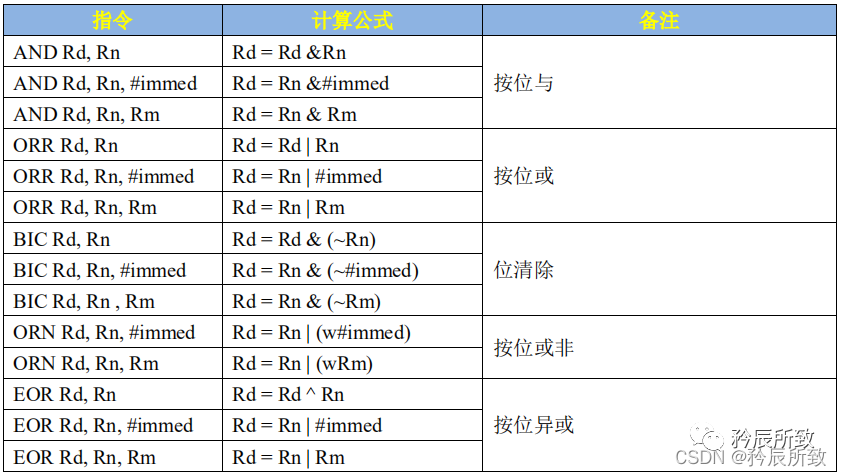
Arithmetic Operation Instructions
The arithmetic operation instructions and the logic operation instructions table are excerpted from the “[Zhengdian Atom] I.MX6U Embedded Linux Driver Development Guide” 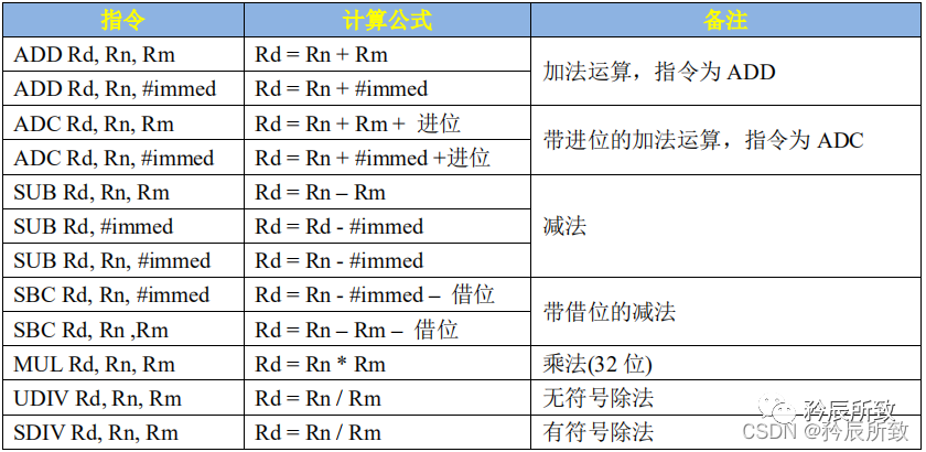
Logical Operation Instructions
3. Code Disassembly Analysis
-
Assembly: The assembly file is converted into a target file (which contains machine code, and the machine code is what the CPU uses; the code burned and saved in Flash memory is machine code). -
Disassembly: The executable file (target file, which contains machine code) is converted into an assembly file.
3.1 Disassembly with Different Compilers
3.1.1 Generating Disassembly Files with Keil
fromelf –text -a -c –output=(change to your desired disassembly name, usually the project name).dis (fill in the path where you generate the axf file based on your project).axf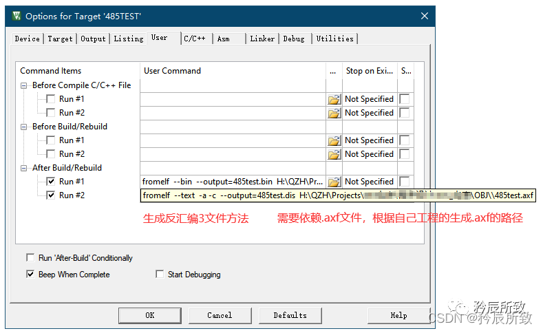 After setting it up, compiling will generate a disassembly .dis file:
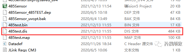
Open it as shown below: 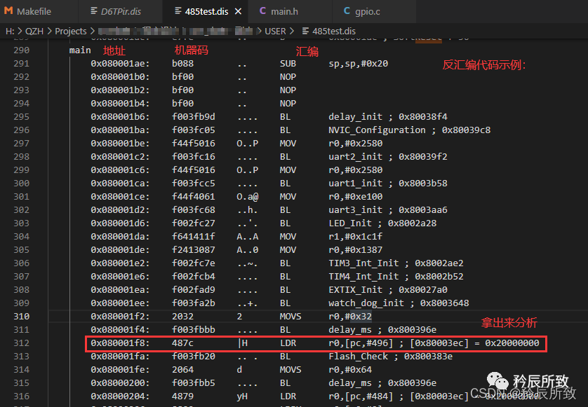 For the statements circled in red in the image above, we can analyze them based on the introduction in the second chapter of this article about the ARM assembly format:
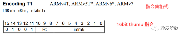
Simple analysis is as follows (I won’t analyze the immediate values = =!): 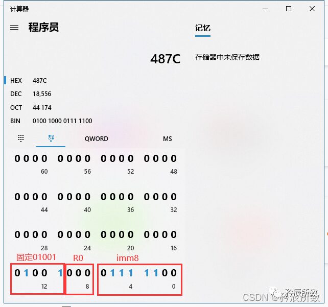
3.1.2 Generating Disassembly Files with GCC
There are two ways to generate ARM architecture assembly code on an X86 architecture computer:
-
Using a cross-compilation toolchain, specifying the -S option can generate an assembly intermediate file. e.g., gcc -S test.c -
Using objdump to disassemble the ARM binary file.
The differences between the above two methods are:
(1) Disassembly can generate ARM instruction opcodes, while the -S generated assembly does not include opcodes.
(2) The disassembled code is optimized by the compiler.
(3) The disassembled code volume is quite large.
For the ARM Cortex-M, the command used is arm-none-eabi-objdump, with common commands as follows:
-
arm-none-eabi-objdump -d -S(省略) a1.o View the disassembled executable segment code of a1.o -
arm-none-eabi-objdump -D -S(省略) a1.o View all disassembled code segments of a1.o -
arm-none-eabi-objdump -D -b binary -m arm ab.bin View all disassembled code segments of ab.bin
For kernels using the arm-none-eabi-gcc toolchain (with STM32CubeMX), use the following method to generate a disassembly file:
$(OBJDUMP) -D -b binary -m arm (the required elf file, usually the project name).elf > (change to your desired disassembly name, usually the project name).dis # OBJDUMP = arm-none-eabi-objdump
-D indicates disassembling all files, -b indicates binary, -m indicates instruction set architecture.
Makefile modification as follows:
...
TARGET = D6TPir
#######################################
# paths
#######################################
# Build path
BUILD_DIR = build
...
PREFIX = arm-none-eabi-
...
OBJDUMP = $(PREFIX)objdump

dis:
 $(OBJDUMP) -D -b binary -m arm $(BUILD_DIR)/$(TARGET).elf > $(BUILD_DIR)/$(TARGET).dis
# $(OBJDUMP) -D -b binary -m arm $(BUILD_DIR)/$(TARGET).bin > $(BUILD_DIR)/$(TARGET).dis
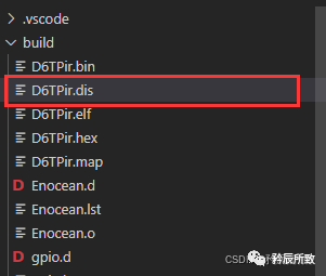
Executing make dis will generate the .dis file: 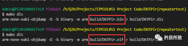
 Open the file to check, and you will find that this assembly language looks a bit different:
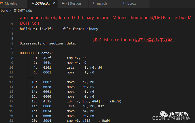
 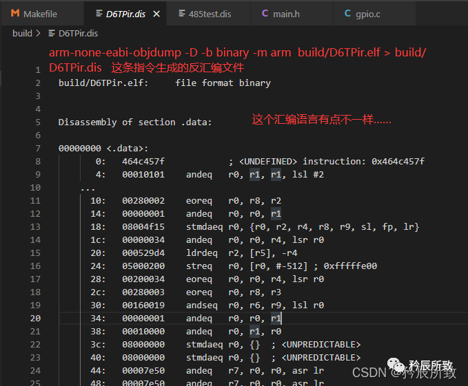 After some research, adding
 -M force-thumb made it look a bit better: 
There are various references online, but I have tested them all and have not found a suitable way to generate completely standard assembly code; the parameters after -M cannot be added randomly and must be based on your cross-compiler. Here, using arm-none-eabi-gcc, you can check the available commands and parameters by using arm-none-eabi-objdump --help: 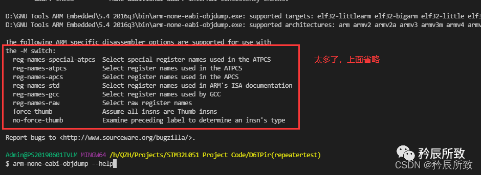 Since I am not very familiar with the assembly under the gcc toolchain, let’s compare the disassembly files with C language for explanation.
3.2 Comparison Analysis of C and Assembly
Having introduced so much, let’s compare a simple program’s disassembly with the assembly language obtained from C language to deepen our understanding, treating it as a practical summary.
Based on STM32L051 (Cortex-M0) core, the purpose is to compare C and assembly, using the simplest program for analysis, without using task peripherals. The program is as follows:
//Previous omitted...
void delay(u32 count)
{
 while(count--);
}

u32 add(u16 val1,u16 val2)
{
 u32 add_val;

 add_val = val1 + val2;

 return add_val;
}
 int main(void)
 {
 u16 a,b;
 u32 c;
 a = 12345;
 b = 45678;
 c = add(a,b);
 while(1)
 {
   c--;
   delay(200000);
  }
}
The corresponding disassembled code is as follows (as it is based on the hardware platform, other exceptions, interrupts, stacks, and some others have assembly code, which are omitted here):
;Omitted previous...
delay
        0x080001ae:    bf00        ..      NOP
        0x080001b0:    1e01        ..      SUBS     r1,r0,#0
        0x080001b2:    f1a00001    ....    SUB      r0,r0,#1
        0x080001b6:    d1fb        ..      BNE      0x80001b0 ; delay + 2
        0x080001b8:    4770        pG      BX       lr
add
        0x080001ba:    4602        .F      MOV      r2,r0
        0x080001bc:    1850        P.      ADDS     r0,r2,r1
        0x080001be:    4770        pG      BX       lr
main
        0x080001c0:    f2430439    C.9.    MOV      r4,#0x3039
        0x080001c4:    f24b256e    K.n%    MOV      r5,#0xb26e
        0x080001c8:    4629        )F      MOV      r1,r5
        0x080001ca:    4620         F      MOV      r0,r4
        0x080001cc:    f7fffff5    ....    BL       add ; 0x80001ba
        0x080001d0:    4606        .F      MOV      r6,r0
        0x080001d2:    e003        ..      B        0x80001dc ; main + 28
        0x080001d4:    1e76        v.      SUBS     r6,r6,#1
        0x080001d6:    4804        .H      LDR      r0,[pc,#16] ; [0x80001e8] = 0x30d40
        0x080001d8:    f7ffffe9    ....    BL       delay ; 0x80001ae
        0x080001dc:    e7fa        ..      B        0x80001d4 ; main + 20
$d
        0x080001de:    0000        ..      DCW    0
        0x080001e0:    e000ed0c    ....    DCD    3758157068
        0x080001e4:    05fa0000    ....    DCD    100270080
        0x080001e8:    00030d40    @...    DCD    200000
;Omitted later
In analyzing this code, the first line in the main function:
0x080001c0: f2430439 C.9. MOV r4,#0x3039
Raises a big question, MOV r4,#0x3039 is not an immediate value (according to the explanation of immediate values in the second chapter), including the next 0xb26e is also not an immediate value, how can it be used directly with mov?
As for this question, I found a relevant article after a simple search online: The Question of Immediate Values in ARM Assembly, which mentions that there is a paragraph in the ARM assembly explanation on the Keil company website:
Syntax
MOV{cond} Rd, #imm16
where: imm16 is any value in the range 0-65535.
So in Keil, can ARM assembly use 16-bit immediate values?
To verify, I slightly modified the program, assigning a value to a that exceeds 16 bits (of course, the function definitions must also be modified accordingly, testing code where a is defined as an unsigned 16-bit integer), and tested it.
If a is set to 65535, the result is as follows (65535 is not an immediate value, and it can be used directly with mov):
0x080001c0: f64f75ff O..u MOV r5,#0xffff
If a is set to 65536, the result is as follows (65536 is an immediate value, and it can be used directly with mov):
0x080001c0: f44f3580 O..5 MOV r5,#0x10000
If a is assigned a value greater than 16 bits, which is not an immediate value, like: 0x1FFFF :
0x080001c0: 4d08 .M LDR r5,[pc,#32] ; [0x80001e4] = 0x1ffff
Indeed, when a exceeds 16 bits and is not an immediate value, it uses the pseudo instruction LDR. Thus, we can conclude:
In Keil’s ARM assembly, numbers within 16 bits (including 16 bits) can be directly assigned using MOV; for values greater than 16 bits, if they are immediate values, they can be assigned directly with MOV, but if they are not immediate values, LDR is used (the method for judging immediate values is still as explained earlier).
3.2.2 Disassembly File Analysis
For the assembly code of the above example program, a simple analysis is as follows: 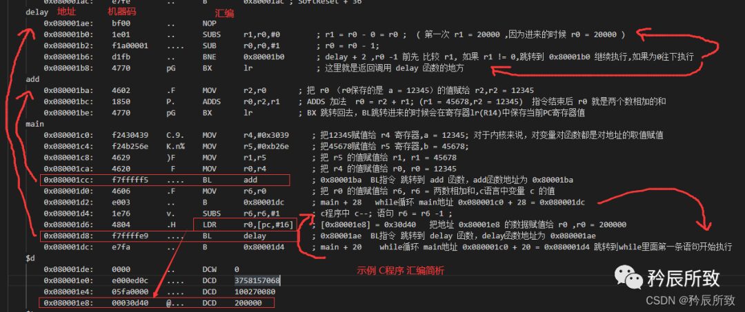 Adding an interesting test for the
 delay function, the above image shows the code for while(count--); changed to while(--count);:
For the add function’s assembly code, the following is the result:
 add
        0x080001ba:    b530        0.      PUSH     {r4,r5,lr}   ; Save the values of r4, r5, lr onto the stack
        0x080001bc:    4603        .F      MOV      r3,r0
        0x080001be:    460c        .F      MOV      r4,r1
        0x080001c0:    191d        ..      ADDS     r5,r3,r4
        0x080001c2:    200a        .       MOVS     r0,#0xa
        0x080001c4:    f7fffff3    ....    BL       delay ; 0x80001ae
        0x080001c8:    4628        (F      MOV      r0,r5
        0x080001ca:    bd30        0.      POP      {r4,r5,pc}  ; Restore the values of r4, r5, lr from the stack
(The assembly shows that instructions with an S at the end, like MOVS, ADDS, indicate that they will affect the value in the xPSR register).
As can be seen, due to the multiple calls of functions, the main function calls the add function, and the add function calls the delay function. Therefore, before executing the add function, the values of r4, r5, and lr are saved onto the stack using push, and after the program execution ends (the function call finishes), the values of r4, r5, and lr are restored.
Although the above program is simple, comparing our C program with the assembly program allows us to gain a deeper understanding of assembly language.