
This article introduces traditional methods for synchronizing distributed data acquisition systems based on SAR ADCs and sigma-delta (Σ-Δ) ADCs, and discusses the differences between these two architectures. We will also explore typical inconveniences encountered when synchronizing multiple Σ-Δ ADCs. Finally, we propose an innovative synchronization method based on the AD7770 sample rate converter (SRC), demonstrating how to achieve synchronization in Σ-Δ ADC-based systems without interrupting the data flow..

Long press to learn more about the AD7770
We live in an interconnected world where everything is synchronized—from bank servers to smartphone alerts. The difference lies in the scale or complexity of the problems to be solved in various specific situations, the synchronization of different systems, and the required precision (or tolerance), or the scale of the systems to be synchronized.
Distributed Systems
In independent designs, the local clock or oscillator used is synchronized by itself. However, when independent designs need to be integrated into a broader system (which we call a distributed system), the perspective of the problem changes, and independent systems should also be designed according to use cases.
To calculate the instantaneous power of an appliance in a system, both current and voltage must be measured simultaneously.Through quick analysis, you can address the problem using three different methods:
-
Using two synchronized single-channel ADCs to measure current and voltage.
-
Using a multi-channel synchronous sampling ADC, where each channel may have an ADC, or each channel has a sample-and-hold circuit.
-
Using a multiplexed ADC and inserting measurement values to compensate for the time shift between voltage and current measurements.
At this point, you may have a reliable solution to the problem. However, if we expand the system requirements from a single appliance to the entire application, what if we need to measure the power of every AC power outlet in the entire factory? Now, your original instantaneous power design must be distributed across the entire factory, ensuring that its design can simultaneously measure and calculate the power of each AC power outlet.
You are now facing a distributed system composed of a set of mutually independent but closely related subsystems. Each subsystem needs to provide sampled data at the same point in time to calculate the instantaneous total power of the factory.
Finally, if we continue to expand the hypothetical application example, imagine if you need to integrate your original design into the power grid. Now, you are detecting millions of watts of power, and any issue in a single link could lead to terrible consequences, such as line damage due to stress, which in turn could cause power outages, resulting in dire outcomes like fires or hospital outages.
Therefore, all systems must be accurately synchronized, meaning that the data captured across the entire power grid must be captured at the same moment, regardless of the geographical situation of the data, as shown in Figure 1.

Figure 1. Power Grid Synchronization
In these cases, you can view it as a critical distributed system, and continuous, fully synchronized data streams must be obtained from each sensing node.
Similar requirements apply to many other critical distributed system examples in aerospace or industrial markets.
Nyquist ADC and Oversampling ADC
Before explaining how to synchronize the sampling moments of multiple ADCs, it is best to understand how each ADC topology determines when to sample the analog input signal, as well as the advantages and disadvantages of each architecture.
-
Nyquist or SAR ADC: The maximum input frequency of this converter is determined by the Nyquist or half-sampling frequency.
-
Oversampling or Σ-Δ ADC: The maximum input frequency is generally proportional to the maximum sampling frequency, typically around 0.3.
On one hand, the input signal sampling moments of the SAR ADC are controlled by applying an external pulse to the conversion start pin. As shown in Figure 2, applying a common conversion start signal to each SAR ADC in the synchronized system will trigger sampling simultaneously at the edge of the conversion start signal. As long as it is ensured that there is no significant delay between the signals, i.e., the conversion start pulse reaches each SAR ADC in a timely manner at the same moment, system synchronization can be easily achieved. Note that the propagation delay between the pulse arriving at the conversion start pin and the actual sampling moment cannot differ by device; this delay is not significant in precision ADCs with relatively slow sampling speeds.
After applying the conversion start pulse, at some time (also known as conversion time), the conversion results will be displayed through the digital interfaces of all ADCs.
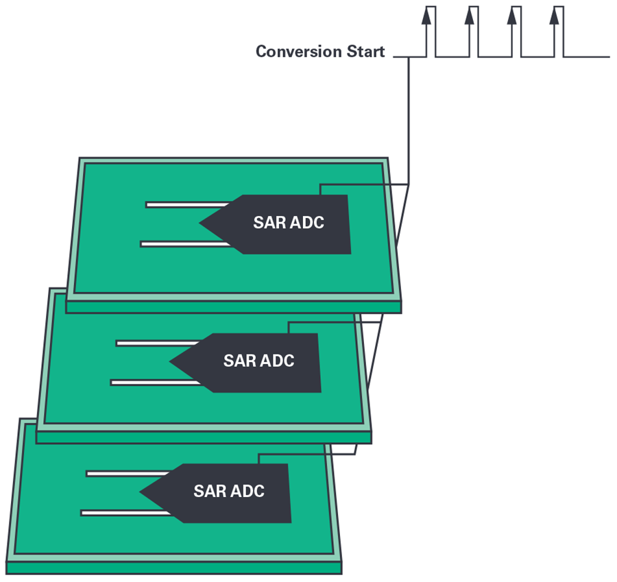
Figure 2. Synchronization of a Distributed System Based on SAR ADCs.
On the other hand, due to the different architecture, the operation of Σ-Δ ADCs is also slightly different. In this type of converter, the internal core (i.e., the modulator) samples the input signal at a frequency (modulator frequency, fMOD) that is higher than the minimum frequency specified by Nyquist, hence it is called an oversampling ADC.
By sampling at a frequency that is strictly higher than required, more samples can be collected. The data from all ADCs is then post-processed using an averaging filter for two reasons:
-
Every 4 averaged samples reduce noise by 1 bit.
-
The averaging filter transfer function is a low-pass filter. When the Σ-Δ architecture pushes its quantization noise to high frequencies, the averaging filter transfer function should be removed, as shown in Figure 3. Therefore, this filtering is accomplished by this averaging filter.
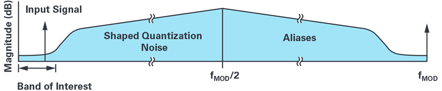
Figure 3. Σ-Δ Noise Shaping.
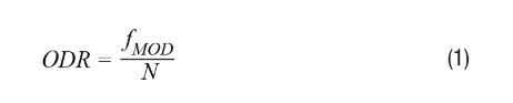
The number of samples averaged, i.e., the extraction rate (N), will determine the output data rate (ODR), which is the rate at which the ADC provides conversion results, measured in samples per second, as shown in Formula 1. The extraction rate is usually an integer with a set of predefined values that can be discretely programmed on the digital filter (i.e., N = 32, 64, 128, etc.). Therefore, by keeping fMOD constant, ODR will be configured based on the value of N within the predefined value set.
The averaging process is typically implemented internally by a sinc filter, and the analog conversion start pulse of the modulator is also generated internally, so the conversion process is not triggered from external control. This type of converter actually continuously samples, tracks the input signal, and processes the obtained data. Once this process (sampling and averaging) is complete, the converter generates a data ready signal, indicating to the controller that the data can be read back through the digital interface. As shown in Figure 4, the workflow of the Σ-Δ can be summarized in four main steps:
-
The modulator samples the signal at frequency fMOD.
-
The samples are averaged through a sinc digital filter.
-
Offset and gain corrections are applied to the data provided by the sinc filter.
-
The data ready pin toggles, indicating that the conversion result is ready to be read by the controller.
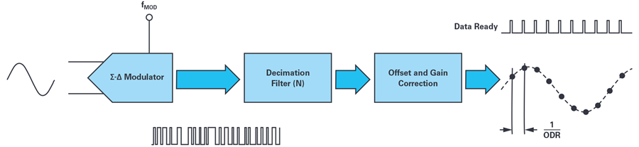
Figure 4. Workflow Diagram of Σ-Δ ADC.
Since there is no external control over when to trigger internal sampling, if you want to synchronize multiple Σ-Δ ADCs in a distributed system, you must simultaneously reset all digital filters, as the averaging conversion start is controlled by the digital filter.
Figure 5 shows the impact of synchronization when all Σ-Δ ADCs use the same ODR and fMOD.
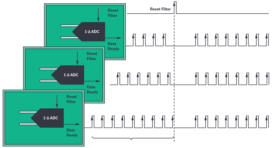
Figure 5. Σ-Δ System Reset Synchronization
As with SAR ADC-based systems, it is essential to ensure that the reset filter pulse reaches each subsystem simultaneously.
However, note that every time the digital filter is reset, the data flow is interrupted because the filter must be reinitialized. In this case, the duration of the data interruption is determined by the order of the digital filter, fMOD, and the extraction rate. In the example shown in Figure 6, the LPF characteristics of the filter will delay the time until valid output is generated.
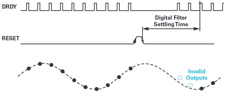
Figure 6. Data Interruption Due to the Establishment Time of the Digital Filter.
Insights on Synchronizing Sampling in Distributed Systems
In distributed systems, a global synchronization signal (which we call Global_SYNC) is shared among all modules/subsystems.This synchronization signal can be generated by the main system or a third-party system (e.g., GPS 1 pps), as shown in Figure 1.
Upon receiving the Global_SYNC signal, each module must resynchronize the instantaneous sampling of each converter (likely its local clock) to ensure simultaneity.In distributed systems based on SAR ADCs, resynchronization is essentially straightforward, as described in the previous section: the local clock (managing the conversion start signal) matches again with the Global_SYNC signal, after which the synchronized signal is obtained.
This means generating frequency scatter, as during synchronization, samples are collected at different times and distances, as highlighted in the blue section of Figure 7. In distributed applications, these scatters may be acceptable, while interrupting the data flow is indeed critical in certain applications, such as power line monitoring mentioned earlier.
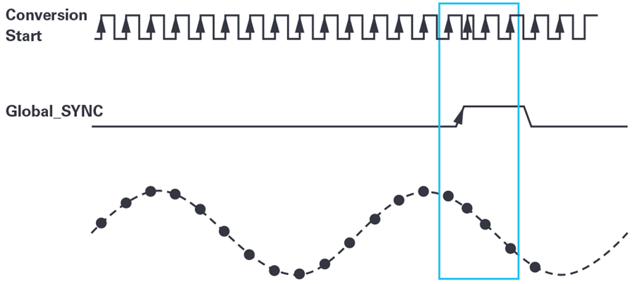
Figure 7. Adjusting the SAR ADC Conversion Process to Match the Global Synchronization Signal.
In Σ-Δ based distributed systems, the process of resynchronizing with the Global_SYNC signal is slightly more complex because the modulator continuously samples the analog input signal, and the conversion process is not externally controlled like the SAR ADC.
To implement synchronization across multiple Σ-Δ based distributed systems, a simple method is to reset the digital filters: discard all modulator samples collected and stored for use in the averaging filter, and clear the digital filter. This means that, depending on the order of the digital filter, it will take some time to determine its output again, as shown in Figures 5 and 6.
Once the digital filter is set up, it will again provide valid conversion data, but considering the time spent on setup, the data interruptions caused by resetting the digital filter on Σ-Δ ADCs may be unacceptable. The higher the frequency at which the distributed system needs to resynchronize, the more interruptions in the data flow will occur, and due to these continuous data flow interruptions, Σ-Δ ADCs may not be applicable in critical distributed systems.
The traditional method used to minimize data interruptions is to use a tunable clock, such as a PLL, which can reduce the error between the global synchronization frequency and the fMOD frequency.Upon receiving the Global_SYNC pulse, a process similar to the following can be adopted to calculate the uncertainty between the conversion start and the Global_SYNC pulse for the Σ-Δ ADC:
-
The controller calculates the sampling moment (by understanding the group delay and calculating backward from the data ready signal, as shown in Figure 8) and the time difference between it and the Global_SYNC pulse. Group delay is a specification in the data sheet that indicates the time interval from sampling the input to the data ready pin toggling (indicating that the sample is ready to be read).
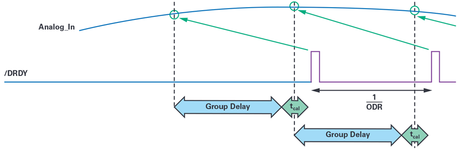
Figure 8. Time Delay Between Sampled Analog Input and Data Ready Toggle.
-
If there is a time difference between the sampling moment and Global_SYNC, the local controller quantifies this time difference (tahead or tdelayed), as shown in Figure 9.
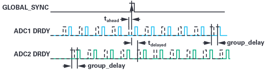
Figure 9. Quantifying the Time Difference Between Each ADC’s Sampling Moment (Assuming Group Delay is Known) and the Global Synchronization Signal.
-
If there is a difference, the Σ-Δ filter can be reset, or the fMOD can be modified to adjust the Σ-Δ sampling over several sampling periods. In either case, a few samples may be missed. Note that by changing the local clock frequency (fMOD), the Σ-Δ ADC will change its output data rate (ODR = fMOD/N), thus the ADC will slow down or speed up the sampling rate of the analog input in an attempt to synchronize with the remaining ADCs and Global_SYNC in the system.
-
If fMOD is updated, then after synchronization, the main clock frequency will return to its original frequency to revert to the previous ODR, while the subsystems will synchronize from that moment.
The process of changing fMOD over time is shown in Figure 10.
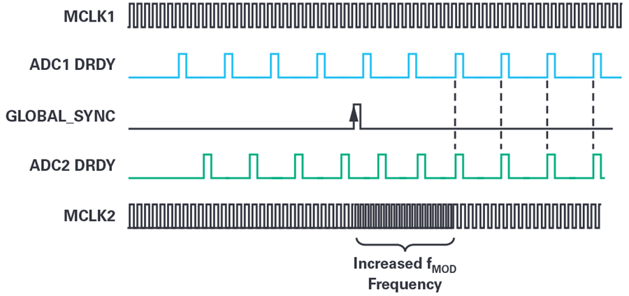
Figure 10. Synchronization Method Using PLL to Tune the Modulator Frequency.
This method may not be applicable in certain cases, as there are several details to consider:
-
Changing the modulator frequency to a non-integer multiple value may be impractical.
-
If frequency can be fine-tuned, the step size of the changed frequency must be very small; otherwise, the digital filter may exceed its limits, resulting in longer synchronization implementation times.
-
If the required ODR changes significantly, it can be addressed by changing the extraction rate (N) instead of changing the modulator frequency (fMOD), but this also means that some samples will be lost.
-
Using PLL means that in addition to its own establishment time, extra power will be consumed before reaching the desired modulator frequency.
In general, the complexity and cost of the entire system increase with the scale of the system, especially compared to SAR ADCs, for which simply adjusting the conversion start to match the Global_SYNC signal easily resolves the issue. Moreover, in many cases, due to the aforementioned system limitations, Σ-Δ ADCs cannot be used.
Seamless Resynchronization of Σ-Δ ADCs Without Data Interruption
The AD7770 series (including AD7770, AD7771, and AD7779) features a built-in SRC. With the introduction of this new architecture, the limitations caused by fixed extraction rates (N) will no longer exist.
The SRC allows you to use decimal numbers (not just integers) as extraction rates (N), so you can adopt any desired output data rate. In previous synchronization methods, since N was fixed, it was necessary to change the external clock to adjust fMOD before implementing synchronization.
With the AD7770 series, N becomes flexibly programmable, and values can be programmed at any time, so there is no need to change fMOD or interrupt data to program the ODR.This new method of resynchronizing Σ-Δ based subsystems utilizes the SRC to simplify the resynchronization process, minimizing the complexity mentioned in previous sections.
The new method is as follows:
-
Upon receiving the Global_SYNC signal, each subsystem checks whether the sampling is synchronized, using the data ready signal as a reference, and utilizes group delay to find the actual sampling moment.
-
If there is a time difference between the sampling moment and the time the Global_SYNC signal was received, the local controller quantifies this time difference (tahead or tdelayed), as shown in Figure 9.
-
At this point, a new ODR is programmed to change the extraction rate (N) through the SRC, temporarily generating a faster or slower ODR. The entire resynchronization operation generally uses 4 samples (6 if the sinc5 filter is enabled on the AD7771), but since these samples are still valid and fully set, they do not cause data flow interruptions.
-
Once the required number of DRDY signals is received, the extraction factor is reset to return to the desired ODR, ensuring that the Σ-Δ ADC remains synchronized with the rest of the subsystems, as shown in Figure 11, without causing data interruptions.
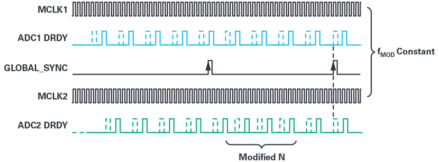
Figure 11. Sample Rate Converter Dynamically Adjusting ODR to Resynchronize Sampling Across All Devices.
Conclusion
Critical distributed systems require all subsystems to synchronize conversions while maintaining continuous data flow. SAR converters provide an intuitive resynchronization sampling method: by readjusting the conversion start signal to match the Global_SYNC pulse.
In applications requiring high dynamic range (DR) or signal-to-noise ratio (SNR), SAR cannot be used, but traditional Σ-Δ converters also become difficult to use because these converters lack the flexibility to readjust without interrupting the data flow.
As demonstrated, the SRC provides a seamless synchronization routine, with lower latency, cost, and complexity compared to other solutions.
The SRC can excel in many applications. Similar to the power line monitoring example, any frequency changes in the line can be compensated by immediately dynamically changing the extraction rate. This ensures that the sampling frequency of the power line remains consistent. As shown in this article, the SRC can also be used for efficient resynchronization in critical distributed systems without causing data flow interruptions and without the need for additional components, such as PLLs.
The AD7770 addresses the traditional issues of synchronizing distributed systems based on Σ-Δ ADCs without losing samples and without the additional costs and complexities associated with PLL-based methods.
👇 Click to Explore the ADI “Chip” World
··