In-Depth Analysis of Linux NVMe Driver: From Principles to Practice
1 NVMe Protocol Basics: Why a New Generation Storage Protocol is Needed
In traditional storage technology, the AHCI protocol for SAS and SATA interfaces has long been the mainstream standard for hard disk communication. However, with the rapid development of flash memory technology, these interface protocols designed for mechanical hard drives can no longer fully leverage the low latency and high concurrency performance potential of flash storage. NVMe (Non-Volatile Memory Express) has emerged as an efficient and scalable host controller interface specifically designed for flash and next-generation non-volatile memory.
1.1 Comparison of NVMe and Traditional Protocols
Compared to AHCI, the NVMe protocol has several significant advantages, as shown in the table below:
Table: Key Feature Comparison between NVMe and AHCI Protocols
| Feature | AHCI | NVMe | Advantage Explanation |
|---|---|---|---|
| Queue Depth | 1 command queue, depth 32 | Up to 65535 queues, each with depth 65535 | NVMe supports massive concurrent operations |
| Interrupt Handling | Global interrupts | Fine-grained interrupt control | Reduces CPU overhead, improves efficiency |
| Data Addressing | Based on PRD | PRP/SGL | More efficient memory page alignment |
| Parallel Processing | Limited parallelism | Extreme parallelism | Fully utilizes multi-core CPU performance |
| Applicable Scenarios | Mechanical hard drives | Flash/new storage | Adapts to future storage demand development |
Life Analogy: Imagine storage devices as warehouses; AHCI is like a warehouse with only one loading and unloading window, where all goods must queue for processing; NVMe, on the other hand, is like a modern warehouse with tens of thousands of intelligent robots, capable of simultaneously handling countless goods, resulting in vastly different efficiency.
1.2 Core Concept System of NVMe
The NVMe protocol is built on a carefully designed core concept system, understanding these concepts is fundamental to mastering how NVMe works:
- • Controller: The control unit of NVMe storage devices, responsible for processing commands issued by the host and managing data transfer. Each controller has a unique identifier, including vendor ID, device ID, and serial number.
- • Namespace: Similar to partitions in traditional hard drives, but more flexible. A namespace is a collection of a certain number of logical blocks, each namespace has an independent ID (NSID) and can be configured with different logical block sizes and characteristics. The host can access multiple namespaces simultaneously, achieving resource isolation and management.
- • Queue Mechanism: The core innovation of NVMe, using dedicated submission queues (SQ) and completion queues (CQ) to manage command execution. The host places commands into SQ, the controller retrieves commands from SQ for execution, and then places the completion status into CQ. NVMe supports strict queue arbitration mechanisms to ensure critical tasks are prioritized.
- • Logical Block Addressing: The smallest read/write unit of NVMe devices is called a logical block (LB), which can be 2KB, 4KB, etc., identified by LBA (Logical Block Address).
- • Doorbell Register: A simple communication mechanism between the host and the controller. The host notifies the controller of new commands to be processed by writing to the doorbell register, and the controller updates the completion command status through the doorbell.
1.3 NVMe over PCIe and NVMe over Fabrics
The NVMe over PCIe protocol defines the scope of NVMe usage, instruction set, and register configuration specifications. The PCIe bus provides a high-speed data transmission channel for NVMe, and its layered structure (physical layer, data link layer, processing layer) provides a lower-level abstraction for NVMe. NVMe SSDs, as PCIe endpoint devices (EP), connect to the host via the PCIe bus.
Key Insight: NVMe is essentially an application layer protocol that fully utilizes the low latency and high bandwidth characteristics provided by PCIe, releasing the performance potential of flash storage through a streamlined command set and efficient queue mechanism.
With technological advancements, NVMe over Fabrics further extends the application range of NVMe, allowing NVMe commands to be transmitted over network technologies such as RDMA and Fibre Channel. This extension enables the advantages of NVMe to extend from local storage systems to network storage environments, providing extremely high performance for data centers.
2 Linux NVMe Driver Architecture: A Deep Dive into the Code
The NVMe driver in the Linux kernel adopts a layered architecture design, with clear responsibilities among modules, working together to provide complete and efficient access to NVMe devices for upper-layer applications.
2.1 Driver Layered Architecture
The layered architecture of the NVMe driver reflects the typical design philosophy of Linux kernel device drivers. The following diagram illustrates the collaboration between various modules:
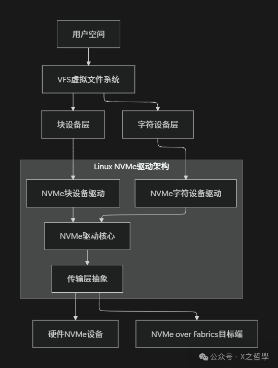
- • Block Device Layer: Provides block device access interfaces through device files like
<span>/dev/nvme0n1</span>, supporting regular file system operations. This layer converts upper-layer file system requests into block requests and hands them over to the NVMe block device driver for processing. - • Character Device Layer: Provides direct user space access through device files like
<span>/dev/nvme0</span>, used for managing commands and I/O. This interface bypasses the traditional block device layer, allowing applications to interact directly with NVMe devices, suitable for specific high-performance scenarios. - • Core Layer: Implements shared core logic, including device initialization, queue management, command processing, etc. The core layer abstracts the basic operations of the NVMe protocol, providing a unified interface for upper layers while isolating the implementation details of different transport layers.
- • Transport Layer: Abstracts the implementation of different physical transports, including PCIe, RDMA, TCP, etc. This design allows the NVMe driver to flexibly support various physical connection methods, whether local PCIe devices or network storage devices.
2.2 Core Data Structure Relationships
There are complex relationships between the core data structures of the NVMe driver, which together form the skeleton of the driver program:
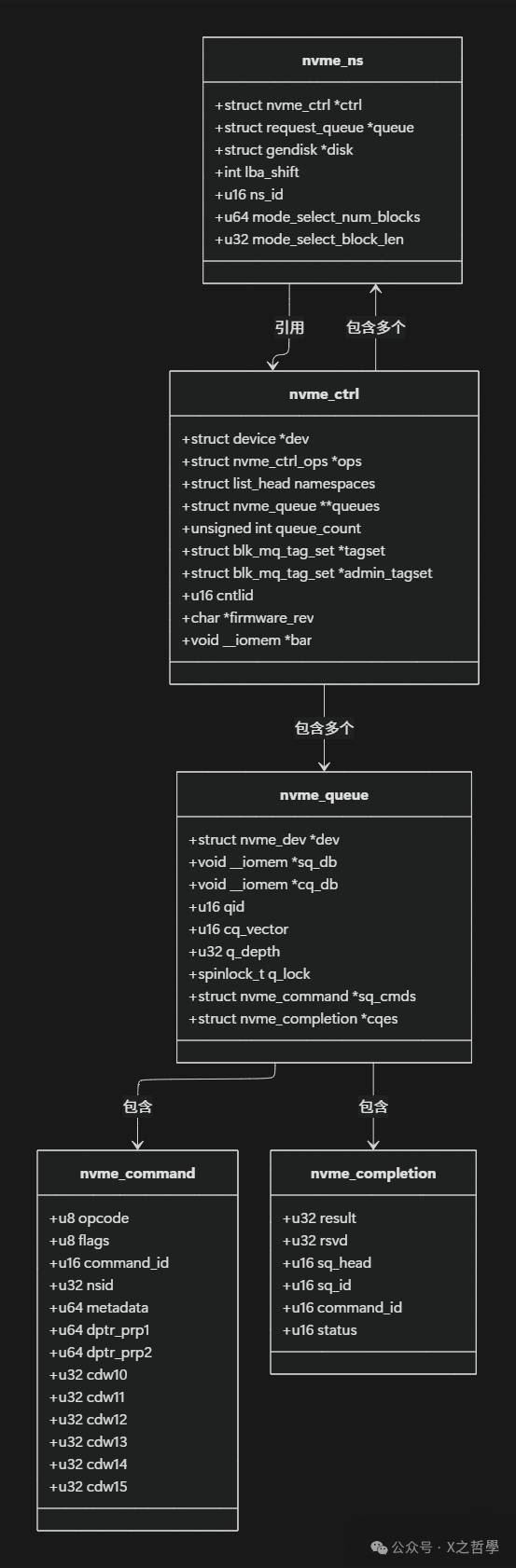
Key Data Structure Analysis:
- •
<span>nvme_ctrl</span>: Represents an NVMe controller, one of the most important data structures in the driver. It maintains the controller’s state information, manages queues, I/O queue collections, and related namespace lists. Each NVMe device has at least one controller instance. - •
<span>nvme_ns</span>: Corresponds to the NVMe namespace, containing configuration information, capacity size, and association with the block device layer. It connects to the kernel block device layer through the<span>struct gendisk *disk</span>member, allowing the namespace to appear as a standard block device. - •
<span>nvme_queue</span>: Encapsulates the queue functionality of NVMe, including submission queues and completion queues. The<span>qid</span>identifies the queue ID, 0 for the management queue, others for I/O queues. The queue lock<span>q_lock</span>protects concurrent access to the queue, ensuring data consistency in a multi-threaded environment. - •
<span>nvme_command</span>and<span>nvme_completion</span>: Represent the command and completion status data structures, following the NVMe protocol standard format. These structures are strictly defined according to NVMe specifications to ensure correct interaction with hardware.
2.3 Device Initialization Process
The initialization of NVMe devices is a complex process involving the collaboration of multiple steps:
- 1. Detection and Identification: After the PCI subsystem discovers the NVMe device, it calls the driver’s probe function to identify the device’s basic information.
- 2. Mapping Register Space: Maps the PCI BAR (Base Address Register) space to the kernel virtual address space for accessing the NVMe controller’s registers.
- 3. Controller Initialization: Configures the controller’s basic parameters, such as queue depth, memory page size, etc., set through the CC (Controller Configuration) register.
- 4. Management Queue Establishment: Creates the administrator submission queue and completion queue for sending management commands.
- 5. Controller Identification: Obtains detailed information and capabilities of the controller through the Identify command.
- 6. I/O Queue Creation: Creates an appropriate number of I/O queues based on the number of CPU cores and system configuration.
- 7. Namespace Enumeration: Identifies all available namespaces and creates corresponding block devices for each namespace.
- 8. Interrupt Configuration: Sets up interrupt mechanisms such as MSI-X for handling command completion notifications.
Code Example: Below is a key code snippet for initialization (simplified based on <span>drivers/nvme/host/core.c</span>):
static int nvme_probe(struct pci_dev *pdev, const struct pci_device_id *id)
{
    struct nvme_ctrl *ctrl;
    int ret;

    // Enable PCI device
    ret = pci_enable_device_mem(pdev);
    if (ret)
        return ret;

    // Map register space
    ctrl->regs = pci_ioremap_bar(pdev, 0);
    if (!ctrl->regs) {
        ret = -ENOMEM;
        goto disable_device;
    }

    // Initialize controller
    ret = nvme_init_ctrl(ctrl, &pdev->dev, &nvme_pci_ctrl_ops);
    if (ret)
        goto unmap;

    // Start reset process
    ret = nvme_reset_ctrl(ctrl);
    if (ret)
        goto uninit;

    return 0;

uninit:
    nvme_uninit_ctrl(ctrl);
unmap:
    iounmap(ctrl->regs);
disable_device:
    pci_disable_device(pdev);
    return ret;
}
3 In-Depth Analysis of I/O Path: From User Call to Hardware Processing
When an application initiates an I/O request, this request must go through multiple software layers before reaching the NVMe hardware device. Understanding this complete path is crucial for performance optimization and troubleshooting.
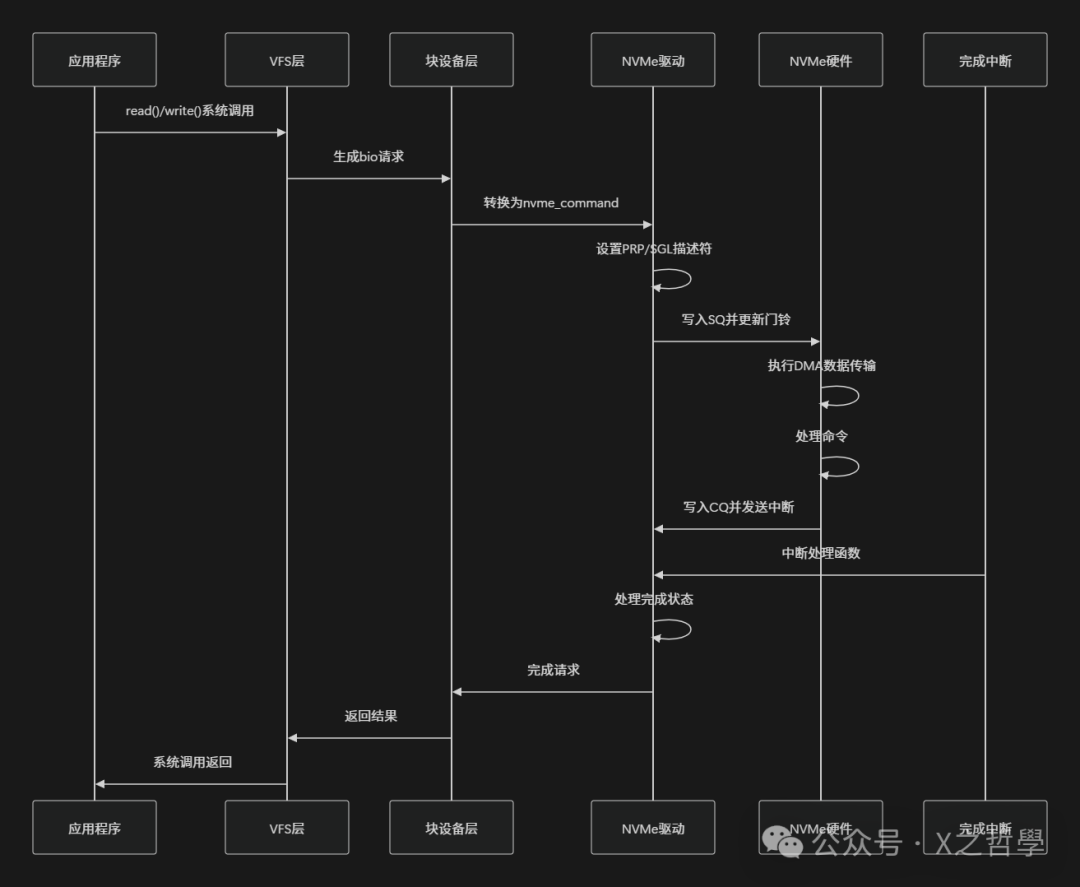
3.1 Command Submission Process
The command submission process involves a complex transformation from user space to kernel space and then to the hardware device:
- 1. User Space Initiates I/O: The application initiates an I/O request through
<span>read</span>/<span>write</span>system calls, and the VFS layer routes the call to the NVMe block device driver. - 2. Block Layer Request Processing: The block device layer encapsulates the request into a
<span>struct bio</span>structure, then converts it into a<span>struct request</span>, inserting it into the request queue. - 3. NVMe Driver Processing: The queue processing function of the NVMe driver retrieves the request from the request queue and converts it into NVMe command format.
- 4. Command Submission: Places the formatted NVMe command into the corresponding submission queue and updates the doorbell register to notify the controller.
Life Analogy: This process is like a delivery system. After the user places an order (system call), the order is assigned to a regional distribution center (block layer), then assigned to a specific courier (NVMe driver), who loads the package (submission queue) and finally rings the doorbell to notify the recipient (doorbell register).
3.2 Data Addressing and Transmission
NVMe supports two main data addressing methods to describe the location of data in host memory:
- • PRP (Physical Region Page): A simple page-based addressing mechanism defined by the NVMe protocol. PRP is a 64-bit physical address pointer, with the last two bits being 0, indicating four-byte alignment. PRP addressing has two methods: direct PRP pointer addressing or PRP List addressing.
- • SGL (Scatter Gather List): A more flexible scatter-gather list mechanism that can describe data buffers in non-contiguous memory areas. SGL supports various segment types, including data blocks, segment bitmaps, and key-value data.
The processing flow of the PRP mechanism is as follows:
// Simplified PRP setup process
static void nvme_setup_prp(struct nvme_command *cmnd, dma_addr_t dma_addr, size_t data_len)
{
    // For small data transfers (<= memory page size), use PRP1 to point directly to data
    if (data_len <= PAGE_SIZE) {
        cmnd->dptr.prp1 = cpu_to_le64(dma_addr);
        return;
    }

    // For large data transfers, need PRP List to describe scattered memory pages
    struct nvme_prp_list *prp_list = dma_alloc_coherent(...);

    // Fill PRP List entries
    for (int i = 0; i < pages; i++) {
        prp_list->prp_entries[i] = cpu_to_le64(page_dma_addrs[i]);
    }

    cmnd->dptr.prp1 = cpu_to_le64(dma_addr);
    cmnd->dptr.prp2 = cpu_to_le64(prp_list_dma_addr);
}
3.3 Command Execution and Completion Handling
After the NVMe controller retrieves the command from the submission queue, it executes the corresponding operation and notifies the host through the completion queue:
- 1. Command Retrieval: The controller periodically checks the doorbell register updates of the submission queue, and upon discovering a new command, retrieves the command content from host memory.
- 2. Command Execution: The controller parses the command type and parameters, executing the corresponding data read/write or other operations.
- 3. Completion Notification: After command execution is complete, the controller writes the completion status to the completion queue and sends an interrupt signal.
- 4. Interrupt Handling: The host’s interrupt handler receives the interrupt, reads entries from the completion queue, and confirms the command execution result.
- 5. Resource Release: The host processes the completion status, releases resources associated with the command, and updates the doorbell register.
The following flowchart illustrates the complete I/O path:
3.4 Error Handling and Timeout Mechanism
In actual deployment, error handling and timeout mechanisms are crucial for system stability:
- • Timeout Detection: The NVMe driver sets a timeout timer for each command, with a default I/O command timeout of 30 seconds and a management command timeout of 60 seconds.
- • Error Recovery: When a command timeout or controller unresponsiveness is detected, the driver attempts to reset the controller or the entire device.
- • Health Status Monitoring: The NVMe driver regularly checks the health status of the controller, including temperature, media wear, and reliability metrics.
4 User Space Tools and Debugging Methods
Mastering NVMe user space tools and debugging methods is crucial for system management and troubleshooting.
4.1 Common NVMe Command Line Tools
NVMe CLI is the official user space tool that can directly interact with NVMe devices, executing management commands and diagnostic operations:
# List all NVMe devices
nvme list

# View controller details
nvme id-ctrl /dev/nvme0 -H

# View namespace information
nvme id-ns /dev/nvme0n1

# View SMART log
nvme smart-log /dev/nvme0

# Execute read test
nvme read /dev/nvme0n1 -s 0 -z 4096 -d output.bin

# Execute write test
nvme write /dev/nvme0n1 -s 0 -z 4096 -d input.bin

# Refresh controller firmware
nvme fw-download /dev/nvme0 --fw=image.bin
nvme fw-commit /dev/nvme0 --action=1

# Create namespace
nvme create-ns /dev/nvme0 --nsze=0x100000 --nscap=0x100000 --flbas=0

# Attach namespace to controller
nvme attach-ns /dev/nvme0 --namespace-id=1 --controllers=0
4.2 System Debugging and Monitoring
The Linux system provides various tools to monitor and debug NVMe devices:
# View PCI device information
lspci -v | grep -i nvme

# View kernel messages
dmesg | grep -i nvme

# Monitor block device I/O statistics
iostat -x /dev/nvme0n1 1

# View NVMe specific statistics
cat /sys/block/nvme0n1/queue/scheduler
cat /sys/block/nvme0n1/device/model
cat /sys/class/nvme/nvme0/queue_count

# Adjust driver parameters
echo 0 > /sys/module/nvme/parameters/default_ps_max_latency_us
4.3 Kernel Debugging and Tracing
For developers and advanced users, the debugging mechanisms provided by the kernel can help deeply analyze NVMe driver behavior:
- • Dynamic Debugging: Enable dynamic debug output for the NVMe driver to view detailed function call paths.
echo 'module nvme +p' > /sys/kernel/debug/dynamic_debug/control- • Event Tracing: Use ftrace to trace events of the NVMe driver, analyzing I/O latency and queue behavior.
echo 1 > /sys/kernel/debug/tracing/events/nvme/enable
cat /sys/kernel/debug/tracing/trace_pipe- • Performance Profiling: Combine the perf tool to profile the NVMe driver, identifying performance bottlenecks.
Table: Summary of NVMe Debugging Tools
| Tool Category | Tool Name | Main Purpose | Applicable Scenarios |
|---|---|---|---|
| Device Management | nvme-cli | Device identification, formatting, firmware updates | Daily management, troubleshooting |
| System Monitoring | iostat, smartctl | I/O statistics, health status monitoring | Performance analysis, preventive maintenance |
| Kernel Debugging | dmesg, dynamic_debug | Driver logs, error tracking | Development debugging, problem diagnosis |
| Performance Analysis | perf, ftrace | Performance profiling, latency analysis | Performance optimization, bottleneck identification |
5 Simple Implementation Example: Directly Using NVMe Character Device
To gain a deeper understanding of how NVMe works, we can bypass the traditional block device layer and directly use the NVMe character device for I/O operations. The following example demonstrates how to send a read command directly through the NVMe character device interface.
5.1 Initialization and Setup
First, we need to open the NVMe character device and set the necessary parameters:
#include <linux/nvme_ioctl.h>
#include <sys/ioctl.h>
#include <fcntl.h>
#include <stdio.h>
#include <stdlib.h>
#include <string.h>
#include <unistd.h>

#define NVME_CHAR_DEV "/dev/nvme0"

int main() {
    int fd;
    int ret;

    // Open NVMe character device
    fd = open(NVME_CHAR_DEV, O_RDWR);
    if (fd < 0) {
        perror("Failed to open NVMe char device");
        return -1;
    }

    // Get device information
    struct nvme_id_ctrl ctrl;
    ret = ioctl(fd, NVME_IOCTL_ID, &ctrl);
    if (ret < 0) {
        perror("NVME_IOCTL_ID failed");
        close(fd);
        return -1;
    }

    printf("Controller: %.20s\n", ctrl.mn);
    printf("Firmware: %.8s\n", ctrl.fr);
    printf("Serial: %.20s\n", ctrl.sn);

    // Continue with other operations...

    close(fd);
    return 0;
}
5.2 Constructing and Submitting NVMe Commands
Next, we construct a specific NVMe read command and submit it to the device:
// Construct NVMe read command
int nvme_read_cmd(int fd, uint32_t nsid, uint64_t slba,
                  uint32_t nlb, void *buffer, size_t buffer_size)
{
    struct nvme_user_io io;
    int ret;

    memset(&io, 0, sizeof(io));
    io.opcode = nvme_cmd_read;    // Read opcode
    io.flags = 0;
    io.control = 0;
    io.metadata = 0;
    io.addr = (unsigned long)buffer;
    io.slba = slba;               // Starting logical block address
    io.nblocks = nlb - 1;         // Number of blocks (0-based)
    io.dsmgmt = 0;
    io.reftag = 0;
    io.apptag = 0;
    io.appmask = 0;
    io.nsid = nsid;               // Namespace ID

    // Submit I/O command
    ret = ioctl(fd, NVME_IOCTL_SUBMIT_IO, &io);
    if (ret < 0) {
        perror("NVME_IOCTL_SUBMIT_IO failed");
        return -1;
    }

    printf("Read command submitted: SLBA=%lu, nblocks=%u\n",
           slba, nlb);

    return 0;
}
5.3 Complete Example Program
Below is a complete example program demonstrating how to read data using the NVMe character device:
#include <linux/nvme_ioctl.h>
#include <sys/ioctl.h>
#include <fcntl.h>
#include <stdio.h>
#include <stdlib.h>
#include <string.h>
#include <unistd.h>
#include <stdint.h>

#define NVME_CHAR_DEV "/dev/nvme0"
#define BLOCK_SIZE 4096
#define BLOCK_COUNT 8

int main() {
    int fd;
    int ret;
    uint32_t nsid = 1; // Default namespace ID
    uint64_t slba = 0; // Start reading from LBA 0
    uint32_t nlb = BLOCK_COUNT; // Number of blocks to read

    // Allocate aligned memory buffer
    void *buffer;
    ret = posix_memalign(&buffer, getpagesize(), BLOCK_SIZE * BLOCK_COUNT);
    if (ret != 0) {
        fprintf(stderr, "Failed to allocate aligned memory\n");
        return -1;
    }

    memset(buffer, 0, BLOCK_SIZE * BLOCK_COUNT);

    // Open NVMe character device
    fd = open(NVME_CHAR_DEV, O_RDWR);
    if (fd < 0) {
        perror("Failed to open NVMe char device");
        free(buffer);
        return -1;
    }

    printf("Successfully opened %s\n", NVME_CHAR_DEV);

    // Get namespace identifier
    struct nvme_id_ns ns;
    ret = ioctl(fd, NVME_IOCTL_ID, &ns);
    if (ret == 0) {
        nsid = le32_to_cpu(ns.ns_id);
        printf("Using namespace ID: %u\n", nsid);
    }

    // Execute read command
    struct nvme_user_io io;
    memset(&io, 0, sizeof(io));
    io.opcode = nvme_cmd_read;
    io.flags = 0;
    io.control = 0;
    io.metadata = 0;
    io.addr = (unsigned long)buffer;
    io.slba = slba;
    io.nblocks = nlb - 1; // 0-based
    io.dsmgmt = 0;
    io.reftag = 0;
    io.apptag = 0;
    io.appmask = 0;
    io.nsid = nsid;

    ret = ioctl(fd, NVME_IOCTL_SUBMIT_IO, &io);
    if (ret < 0) {
        perror("NVME_IOCTL_SUBMIT_IO failed");
    } else {
        printf("Successfully read %u blocks from LBA %lu\n", nlb, slba);

        // Print the first 16 bytes as an example
        printf("First 16 bytes: ");
        for (int i = 0; i < 16; i++) {
            printf("%02x ", ((unsigned char*)buffer)[i]);
        }
        printf("\n");
    }

    close(fd);
    free(buffer);
    return 0;
}
5.4 Compilation and Execution
Compile and run the above example program:
# Compile the program
gcc -o nvme_read_example nvme_read_example.c

# Run the program
sudo ./nvme_read_exampleNotes:
- • Root privileges are required to directly access the NVMe character device.
- • Ensure the NVMe character device exists (check
<span>/dev/nvme*</span>device files). - • In actual production environments, block device interfaces are typically used; character devices are mainly for management and debugging.
6 Conclusion
The NVMe driver in the Linux kernel adopts a carefully designed layered architecture, with the core layer abstracting general NVMe protocol operations, and the transport layer supporting various connection methods. The block device layer and character device layer meet different application scenario needs. Key data structures such as <span>nvme_ctrl</span>, <span>nvme_ns</span>, and <span>nvme_queue</span> closely collaborate to manage the controller’s state, namespace configuration, and queue operations.
From the perspective of the I/O path, NVMe commands undergo a complete lifecycle from user space system calls, to request encapsulation in the block device layer, to command conversion in the NVMe driver, and finally notifying the hardware to execute through the doorbell register. The PRP/SGL data addressing mechanism, completion queue interrupt handling, and error recovery mechanisms in this process all reflect the efficiency and reliability of NVMe design.