The buzzer is a common device, which can be divided into passive and active types. Choose different types of buzzers based on project requirements. In a recent project, we used an active buzzer. As usual, we first designed the circuit board and then proceeded to programming.
The schematic in the project is as follows:
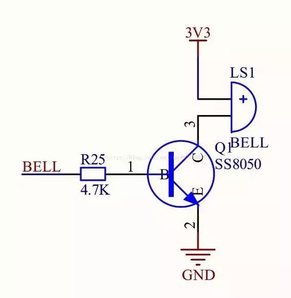
If the I/O output performance cannot be guaranteed, pull-up or pull-down resistors can be added as needed.
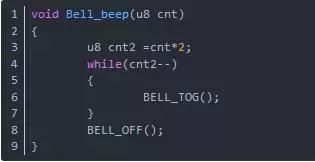
To get to the point: in the program, the driver for this buzzer is just a high-low level drive. When the high level turns on the transistor, the buzzer sounds; when the low level turns off the transistor, the buzzer does not sound. This is indeed very simple, and initially, I wrote the program like this:
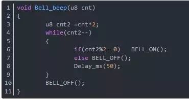
Of course, if the microcontroller does not have a good I/O toggle function, it can be modified like this:
Here is a brief explanation:
1)
Functionality: Buzzer sound driver
Parameters: Number of times the buzzer should sound
2)
The input count parameter needs to be doubled within the function. This is because the parameter passed is intended to make the buzzer sound cnt times continuously. However, the buzzer also has times when it does not sound. In other words, the buzzer needs to be turned off after each sound; without the off operation, it will not sound a few times but will continuously sound once, which is easy to deduce.
3)
After the while loop, a buzzer off operation needs to be added.
If the parameter passed is 2, the goal is to make the buzzer sound twice. Based on the execution steps of the program:
cnt2 becomes 4.
1st while(4) buzzer on, cnt decrements to 3
2nd while(3) buzzer off, cnt decrements to 2
3rd while(2) buzzer on, cnt decrements to 1
4th while(1) buzzer off, cnt decrements to 0
5th while(0) exits the while loop
It can be seen that after the while loop, the buzzer is already in the off state, but for safety, we ensure that after the function is called, the buzzer is in the off state. For instance, the first function’s I/O toggle needs to be more secure, as the code only shows the toggle, not the state after the toggle.
Thus, a simple buzzer circuit and driver program have been reviewed, and now for the practical part:
When writing programs, efficiency is often emphasized. For example, in this buzzer driver, the driving process may reduce efficiency. Those skilled can quickly notice this, which is the issue of delay. However, as mentioned above, not using delays is also not feasible. Therefore, in pursuit of efficiency, I tried a different method to drive the buzzer.
The code is as follows:
Implementation is also quite simple; let’s briefly explain the principle:
1) First, provide the I/O configuration for driving the buzzer,
2) Next, configure the timer
3) Finally, implement the timer interrupt function
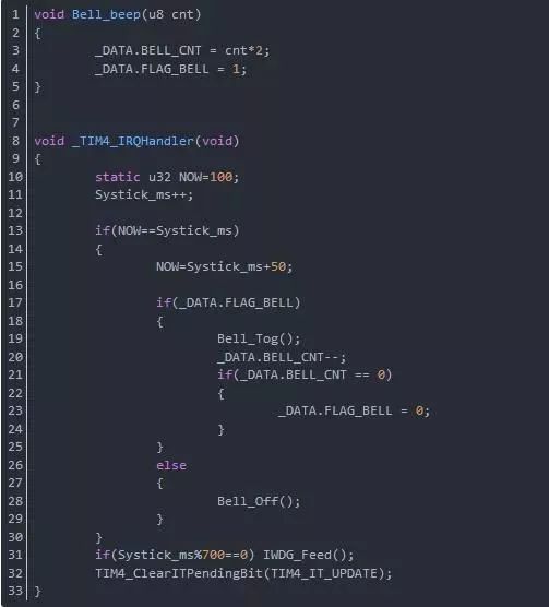
The timer I chose is the simplest one in the project’s microcontroller, configured for a 1ms interrupt, capable of providing overflow interrupts. In fact, I often use this timer for counting system running time Systick_ms. However, this project does not utilize this system time, so I will use this timer.
Implementation method:
1. Similarly, when calling the buzzer driver function, the interface remains the same, with the input parameter still being the number of times the buzzer should sound.
2. The function body has changed; here, it has been modified to assign two variables. The first BELL_CNT corresponds to cnt2 in the ordinary method, which will not be detailed further here. The second is FLAG_BELL, which is used to save the state variable indicating whether the buzzer needs to be driven. Therefore, since this is a driving function call, this variable must be true.
3. In the timer interrupt function, a static variable NOW has been added, which serves to create a 50ms time slice with Systick_ms, for what? It’s definitely for the delay between the buzzer’s on and off. It simulates software delay. Now let’s analyze this segment of code:
1) First, this NOW and Systick_ms must be assigned unconditionally to ensure a 50ms time slice. The corresponding code is NOW=Systick_ms+50;
2) Check if the buzzer driving state variable is true; if it is not true, turn off the buzzer, which is also unconditional.
3) If the state variable is true: the buzzer first toggles Bell_Tog(); of course, if there is no toggle function, the above method of checking cnt can also be used; I won’t elaborate as they are the same. At the same time, the count decrements BELL_CNT–; and check if it has decremented to 0; if it has, it means it has finished sounding, so the state variable is set to false. When re-entering, regardless of whether the buzzer is on or off, it will execute the off operation, which is similar to the safety mentioned above.
4) Finally, these two variables are global variables presented in the form of a structure, as in many situations these two functions may not be in the same C file. If they must be written in one C file, this point can be ignored.


To help everyone learn better, Changxue Electronics Network has specially added a WeChat public account for microcontrollers and EDA, pushing relevant knowledge every day, hoping to assist you in your studies!