(This article is adapted from electronicdesign)
Digital feedback control is widely used to manage various devices, collectively referred to as controlled devices (DUC), such as motors, temperature systems, servo actuators, system pressure regulators, and flow controllers. The goal of digital feedback control design is to establish the performance standards required for the Analog-to-Digital Converter (ADC) of the sensors and the Digital-to-Analog Converter (DAC) of the controllers.
In traditional analog controllers (as shown in Figure 1), signals are processed as proportional voltages by circuits based on operational amplifiers, which implement the core control loop functions, namely gain/multiplication, summation/addition, differential/subtraction, differentiation, and integration. In contrast, digital controllers perform control calculations on digital data streams, with their control algorithms implemented through digital logic hardware or running on code in microcontrollers (MCUs) or programmable logic controllers (PLCs).
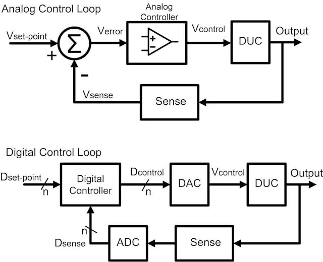
Figure 1: Traditional analog control typically employs proportional voltages throughout the system. In contrast, digital control loops using data streams allow for easy modification of control algorithms through code-based methods.
Digital controllers simulate the behavior of these analog controllers through appropriate digital hardware and software. They require ADCs and DACs to have sufficient performance to capture and regulate the behavior of the controlled devices (DUC) with appropriate time and amplitude resolution.
Transitioning to Digital Controllers
Although many integrated circuits still use analog feedback in specific applications, such as bias control, voltage regulation, phase-locked loops (PLLs), or automatic gain control (AGC), general-purpose embedded controllers and industrial controllers have shifted to digital implementations for greater flexibility and integration. The simulation of analog functions by digital systems means that digital systems must adequately replicate analog functionality, with ADCs and DACs forming the critical interface between the digital controller and the real world.
In practical industrial environments, most digital controllers do not strictly rely on the mathematical methods of classical control theory but instead use Proportional-Integral-Derivative (PID) control units, whose parameter tuning is often done empirically. MCUs and PLCs typically can perform complete digital PID implementations internally, making them cost-effective, efficient, and easy to tune through software parameter modifications.
Several key factors must be considered in digital control design:
-
The output accuracy required from the controlled device (DUC)
-
The required DAC resolution, clock frequency, and ripple performance
-
The sensor accuracy, ADC resolution, and sampling rate
-
The precision of digital computations
While the first two considerations apply to both analog and digital systems, the specific performance of ADCs and DACs is particularly critical in digital implementations. The sensor accuracy should exceed the required output accuracy of the controlled device (DUC), and the computational precision of the control algorithm should surpass the performance of the DAC to avoid introducing new errors.
The continuous-time signals of the controlled device (DUC) (as shown in Figure 2) are sampled in time and quantized in amplitude by the ADC, generating a digital data stream input to the digital controller. Therefore, the sampling rate and resolution of the ADC will limit the perception and control accuracy of the controlled device (DUC). Estimating an appropriate ADC sampling rate typically requires examining the time-domain step response of the controlled device (DUC)—the higher the amplitude resolution of the ADC and the more samples taken per unit time, the finer the control achievable by the digital system.
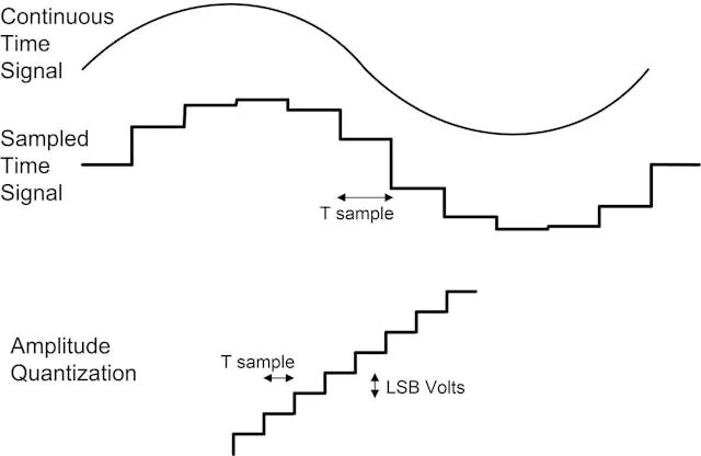
Figure 2: The signals used in digital control are both sampled in time and quantized in amplitude. To accurately represent these signals, both the sampling rate and amplitude resolution must be determined.
Testing Setup for DUC
In control system design, the stability of the controlled device (DUC) is a key characteristic. Feedback control loops can improve the stability of the controlled device, but this improvement is only effective within its bandwidth range. High-frequency variations in the controlled device that exceed the bandwidth of the control system cannot be compensated.
Figure 3 illustrates a testing setup: in a stable and disturbance-free environment (e.g., no load or temperature changes), a fixed input should produce a fixed output from the controlled device, with a voltage-controlled oscillator (VCO) being an example. Even if the input analog signal is stable, its inherent phase noise and frequency jitter may cause variations in the output frequency.
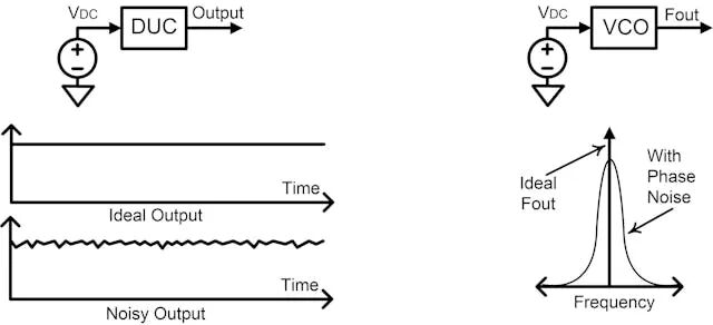
Figure 3: The stability of the controlled device (DUC) should be checked. Control loops can improve the stability of the DUC, but this improvement is limited to the bandwidth of the loop. High-frequency instability can pose problems.
The DC transfer function of the DUC describes the relationship between the input (e.g., voltage) and output (e.g., frequency), determining the required DAC resolution (as shown in Figure 4). By mapping the required output accuracy range of the system to the corresponding DAC input value range, the minimum step size required for the DAC (i.e., the least significant bit, LSB) can be determined. For robust design, it is recommended to include at least 8 or more DAC LSB step sizes within the required accuracy window.
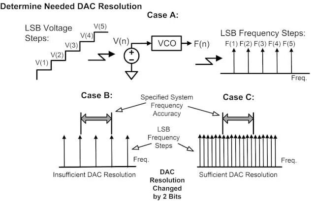
Figure 4: The least significant bit (LSB) resolution of the DAC should be small enough to ensure that the outputs generated by multiple LSB steps fall within the accuracy requirements set by the system.
One testing setup (Case A) is to input a series of voltage step signals to the controlled device (DUC) and measure the output frequency. The input signal should come from a low-noise DC power supply to completely isolate and test only the performance of the DUC. If the initial resolution is insufficient (as shown in Case B), increasing the bit count of the DAC can improve performance, as illustrated in Case C of Figure 4.
If the system’s accuracy range includes multiple DAC LSB steps, design margin is created, which protects the design from minor errors or drift. However, if the DAC resolution is inadequate, the control system may not achieve the required accuracy of the controlled device (DUC) during closed-loop operation.
As shown in Figure 5, for a fixed digital input, the output of the DAC should ideally remain stable. Some DACs (especially those using Pulse Width Modulation (PWM)) may produce ripple, and if the output deviation exceeds the DAC’s LSB, the LSB resolution becomes irrelevant.
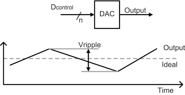
Figure 5: The non-ideal performance of the control DAC should also be examined. Ideally, a fixed digital input should produce a fixed voltage output. However, output deviation (commonly referred to as “voltage ripple”) may exist. This is a common issue with PWM DACs.
The Role of ADC
The role of the ADC is to digitize the output of the sensor circuit of the controlled device (DUC), with its resolution, repeatability, and accuracy needing to exceed the overall accuracy requirements of the system. Using the same approach as determining DAC resolution, the resolution of the ADC should be set higher than the expected DUC output resolution.
Determining the sampling rate of the ADC requires extra caution. While control engineering textbooks may relate the ADC sampling rate to the bandwidth of the control loop, in practical applications, referencing the step response of the DUC (as shown in Figure 6) is an effective method.
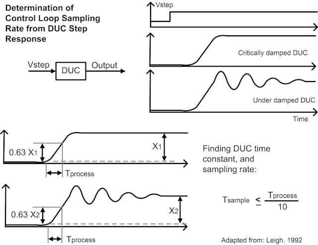
Figure 6: The speed of the controlled device (DUC) response to step inputs determines the required sampling rate for the control loop. A rapidly responding DUC requires a higher number of samples per second than a slower device to provide appropriate feedback data.
The open-loop step response reflects the DUC’s reaction to sudden input changes, revealing critical time constants (i.e., process time, Tprocess). A practical guideline is to set the sampling period (Tsample) to collect at least 10 samples within the process time (Tprocess). This ensures that the controller accurately perceives the system dynamics and responds appropriately.
Applying step inputs within the midpoint operating range of the DUC ensures meaningful characteristic analysis results. For example, for a DUC with an input range of 0 to 1V, applying a step signal from 450mV to 550mV avoids potential non-linear issues at the extremes.
Once the minimum bit depth and sampling rate of the ADC are determined, suitable converters can be selected, aiming for performance that meets or exceeds the calculated requirements. The maximum sampling rate of the selected ADC will determine the operating rate of the loop. Subsequently, a DAC with matching or superior resolution and speed can be chosen to support the output side’s operation.
These methods enable designers to determine the performance of ADCs and DACs in digital control loops, thereby supporting a variety of possible control algorithms—from PID to more complex or custom algorithms.
END