MAKER:DIY GUY Chris/Translated by: 趣无尽
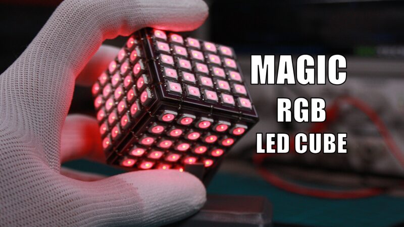
The six faces of this colorful glowing cube are made up of a 5 X 5 WS2812 LED matrix, with each face connected through reserved soldering points. Each matrix plane is driven by an RP2040 chip, and theoretically, you can enlarge this cube and increase the number of cubes to create larger and more complex polyhedra. Through this project, you can learn the following: 1. Understand the basic circuit operation of the RP2040 MCU. 2. Skills in assembling electronic devices. 3. Skills in using WS28xx LEDs to achieve colorful matrix displays.
If you can gain more creative inspiration from this project and create your own unique works, that would be fantastic!

Component List
RP2040 Microcontroller × Several Solder Pads × 1 Soldering Iron × 1 Low-temperature Solder Paste × 1 Scraper × 1
Design the Circuit
 First, choose the appropriate components to design the circuit. I am using the RP2040 MCU from the Raspberry Pi Foundation: https://datasheets.raspberrypi.com/rp2040/hardware-design-with-rp2040.pdf
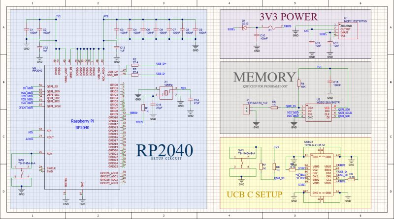
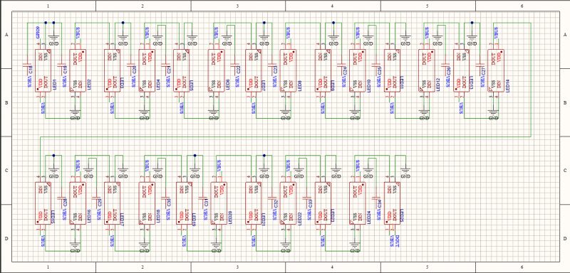 As shown, create a circuit design in Altium Designer and then upload the circuit schematic. The schematic is divided into four main blocks:
 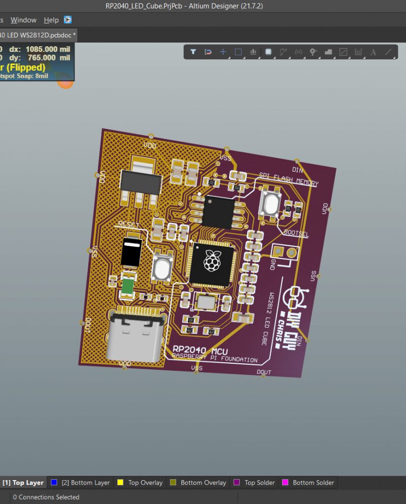 1. The RP2040 chip visualizes the components required around the microcontroller. It is strongly recommended not to overlook the decoupling capacitors for the MCU power lines, and to place them closer to the power pins in the PCB design, with a suggested capacitor value of 100nF for each power pin. 2. For memory chips, I used a QSPI storage chip to load program code, recommending the W25Q128JVS. 3. Voltage Regulator
 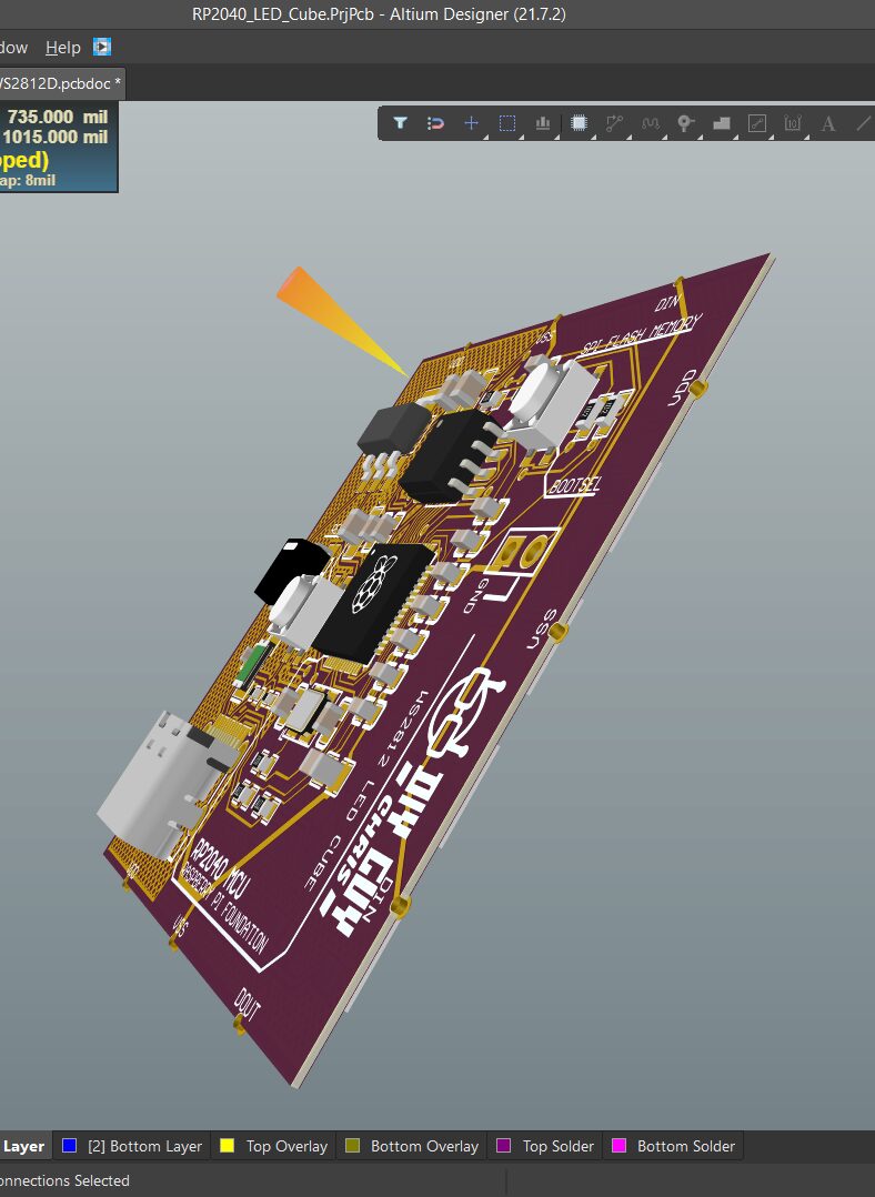 As shown, the MCU requires a voltage of 1.1V generated internally and a voltage of 3.3V supplied externally by the regulator. 4. USB C Interface
 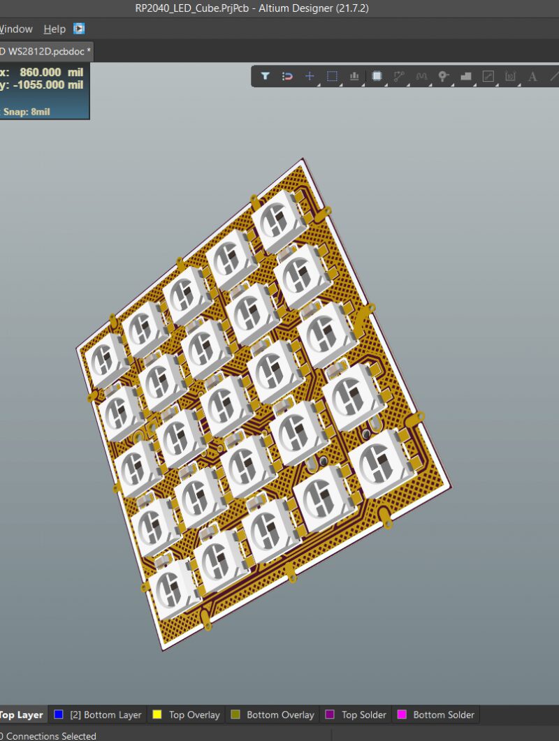 As shown, I used Type C as the connector. I connected 25 WS2812 RGB LEDs in series, equipped with some 100nF decoupling capacitors. Regarding PCB design, you can choose your own shape. In my project, it is a 40mm x 40mm cube shape. The PCB design GERBER files can be downloaded from the project file library: https://make.quwj.com/project/428
Assemble the PCB Mainboard
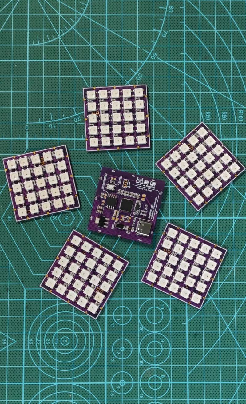
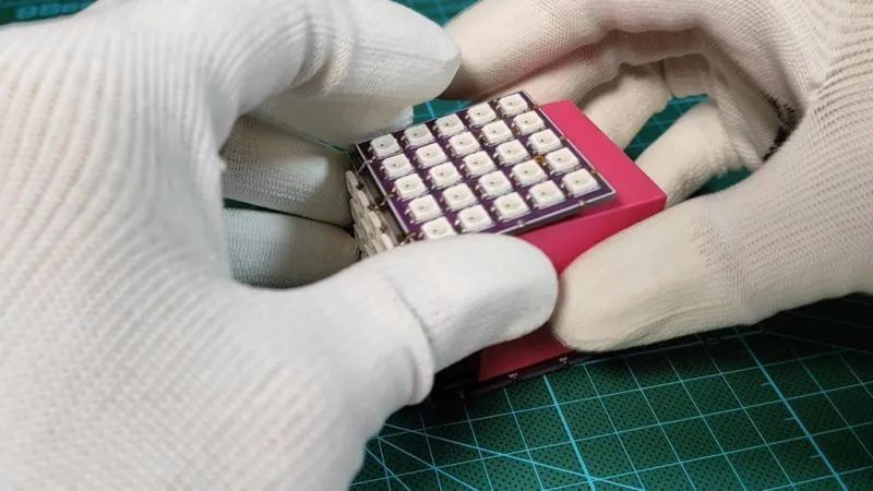
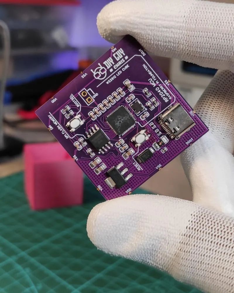 1. Solder the electronic components on the top and bottom one by one, then solder the five RGB LED panels on the bottom, forming a cube with a total of six faces. Ensure that the solder paste is evenly distributed during soldering.
 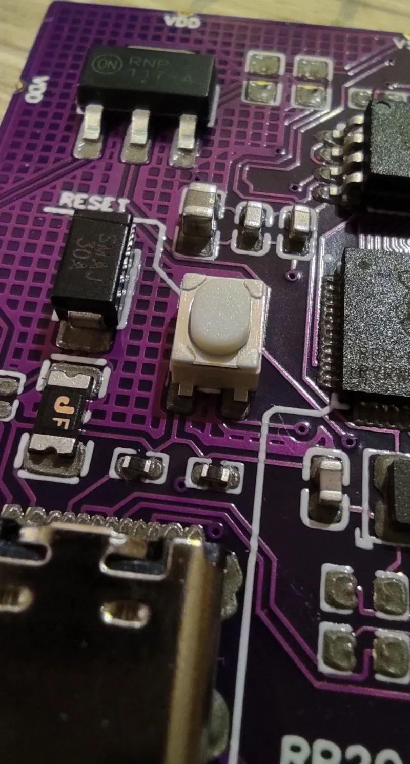 2. Those unfamiliar with PCB soldering can refer to the GERBER files, especially the BOM and P&P files. The materials can be found in the project file library.
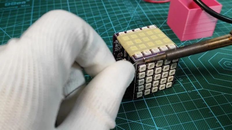
 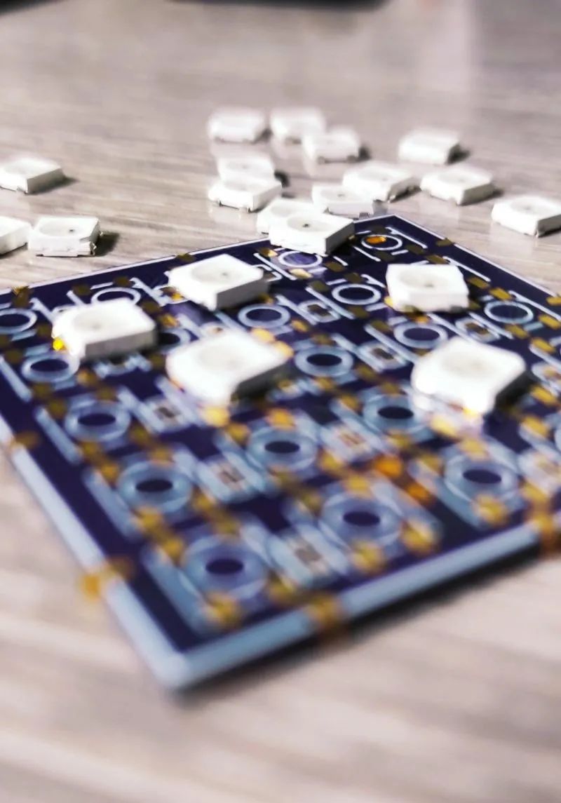 3. Use a hot plate to assemble the cube components. Since my hot plate temperature is low, I used low-temperature solder paste.
 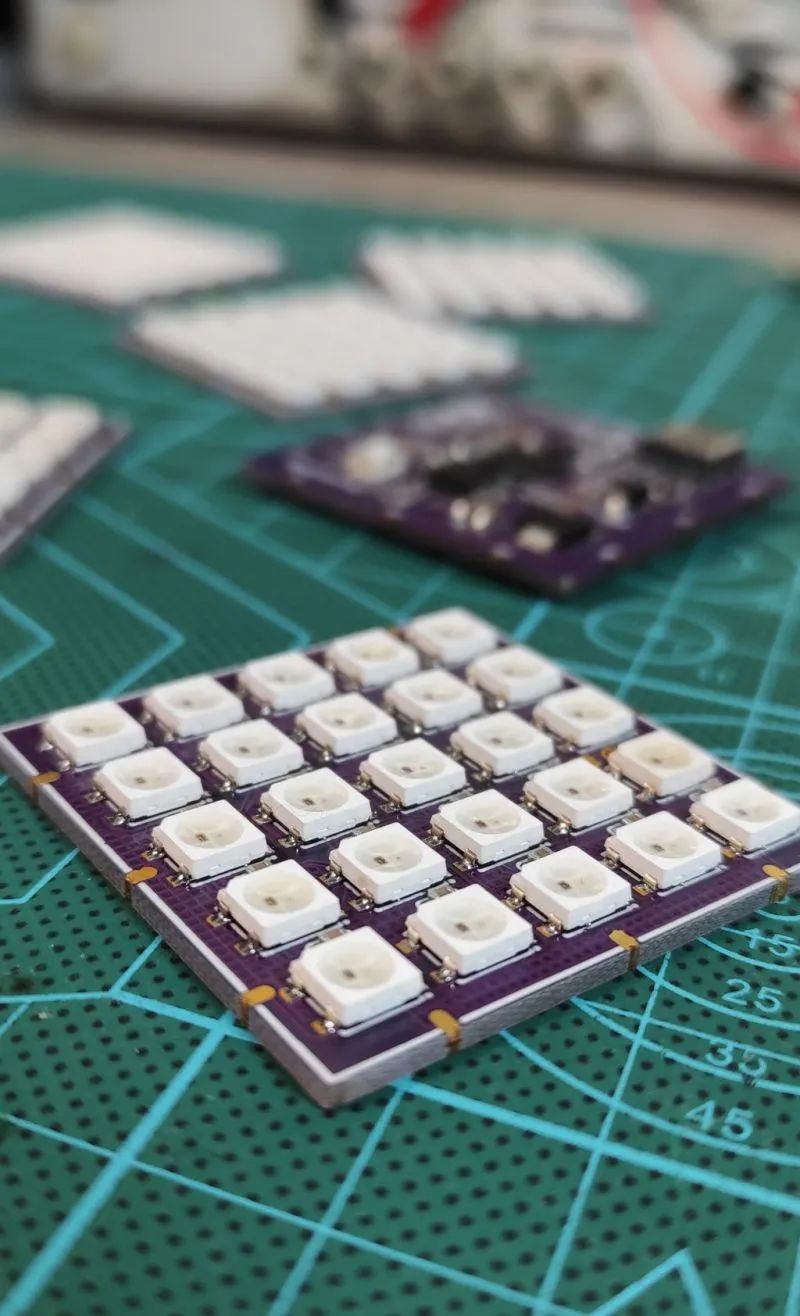 Note: After assembly, do not forget to clean the flux residue from the assembly board.
Burn the Code
Program it using Arduino IDE, preset APIs in the Neopixel library and control the WS2812 LEDs through an output pin. This is the advantage of this type of RGB LED, as we can connect them in series and control them through one output. In this project, one pin controls 150 LEDs. I sorted its functions using animations, then added the Pico board to the IDE in the board manager. Note: On the first run, when you connect the mainboard via USB, it will not appear in the Arduino port list, but simply click upload after accepting the code, and it will appear in the port list. The cube code can be downloaded from the project file library: https://make.quwj.com/project/428
3D Print the CAD Shell
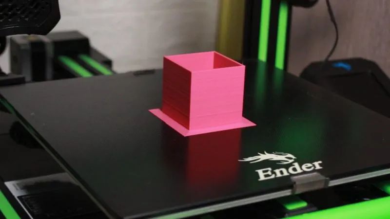
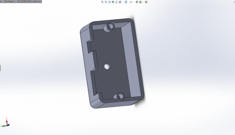
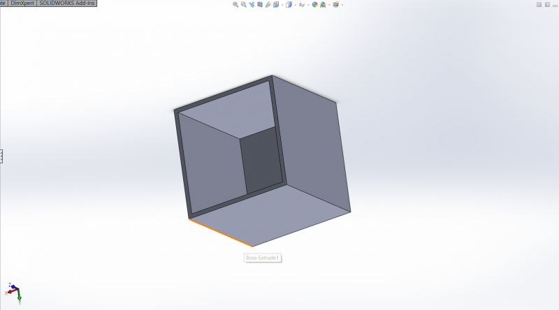
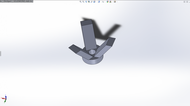 As shown, you can now 3D print the shell. In the shell, I designed a nice bracket using Solidworks that can be used to hold the cube.
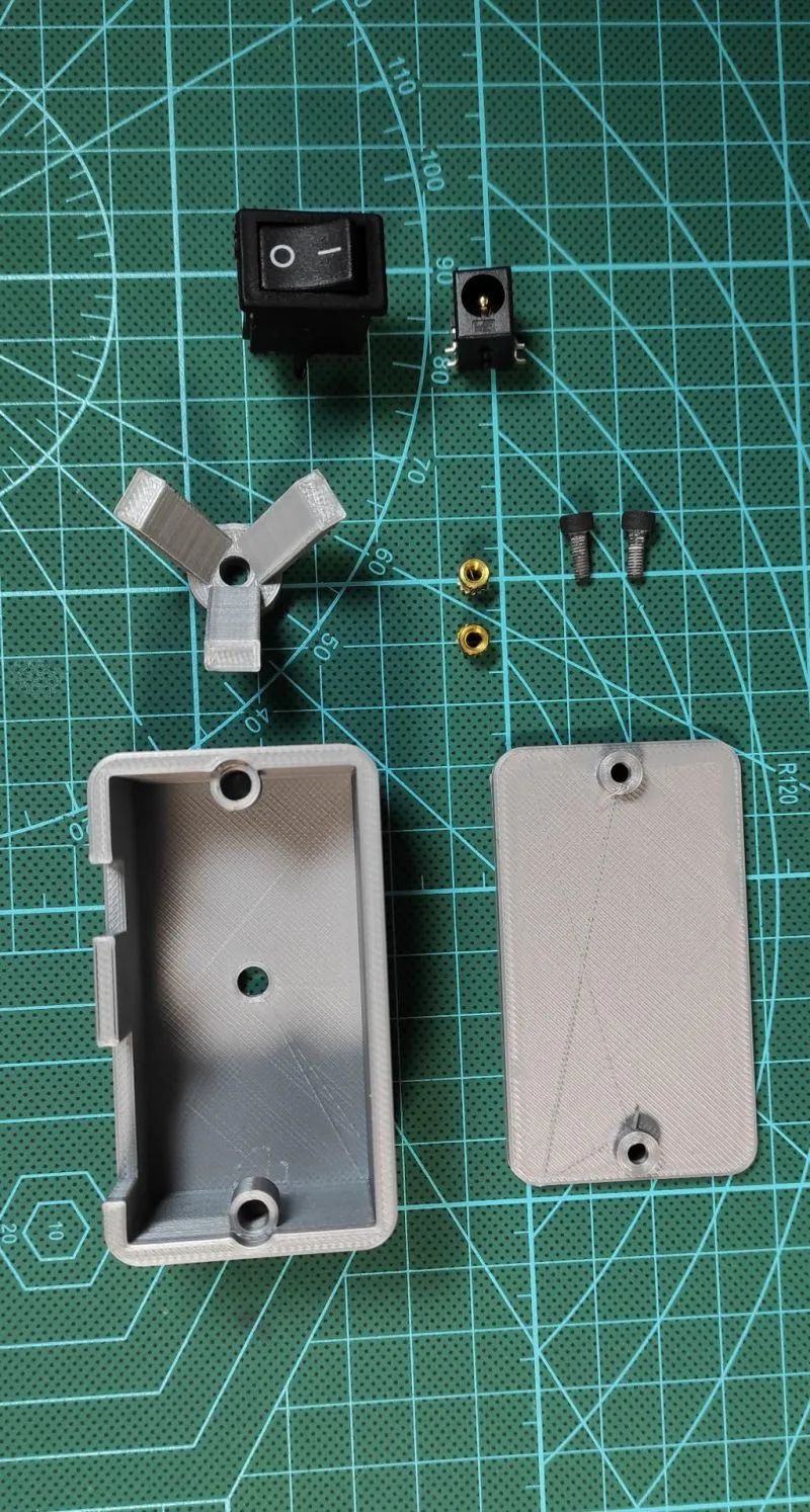
All STL files can be downloaded from the project file library: https://make.quwj.com/project/428
Final Assembly and Testing
 Design the PCB to connect the side pins to VDD, VSS, Din, and Dout, as follows: First Block —> Second BlockVDD —> VDDVSS —> VSSDout —> Din
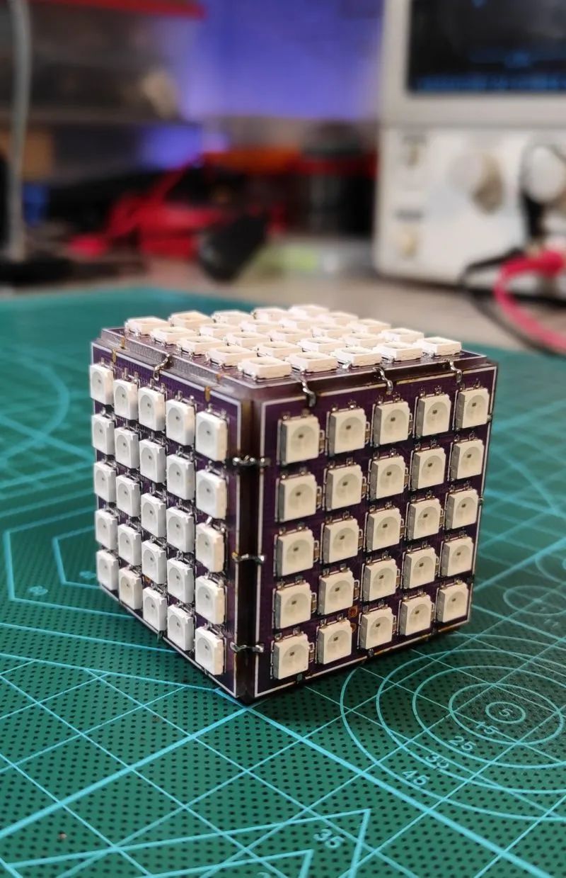 Then connect the next block’s Din side to the Dout side of the previous block, and continue this way.Note that the first block starts with the one containing the microcontroller board.
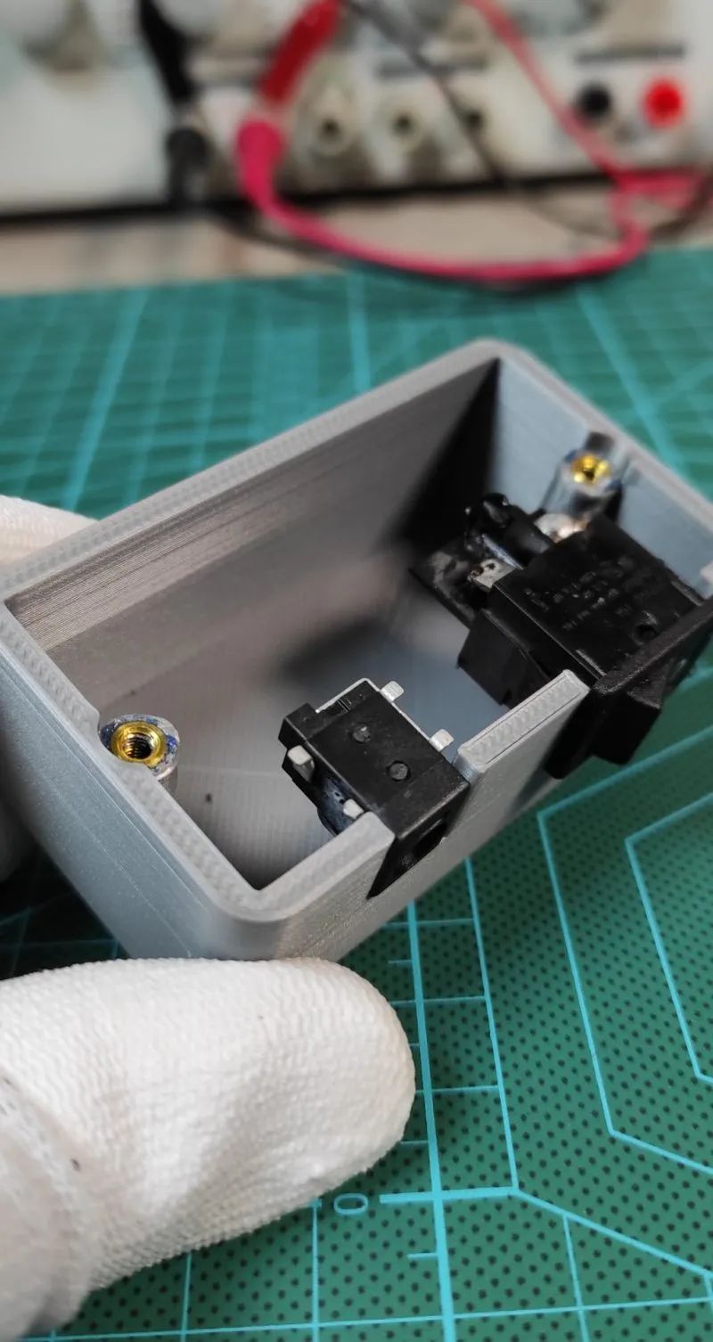
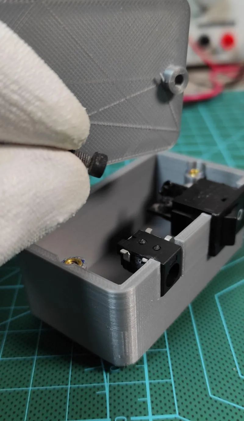
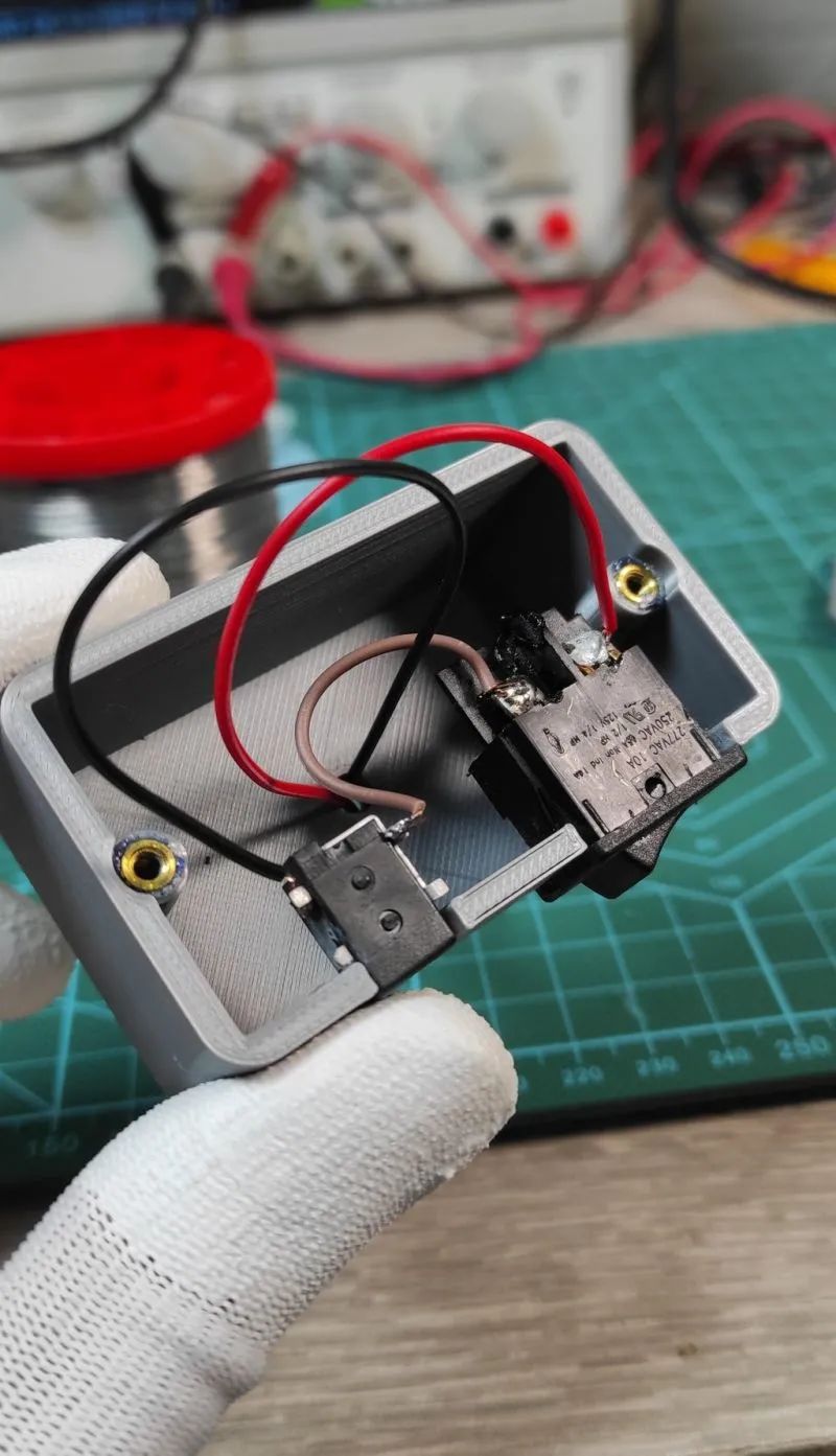
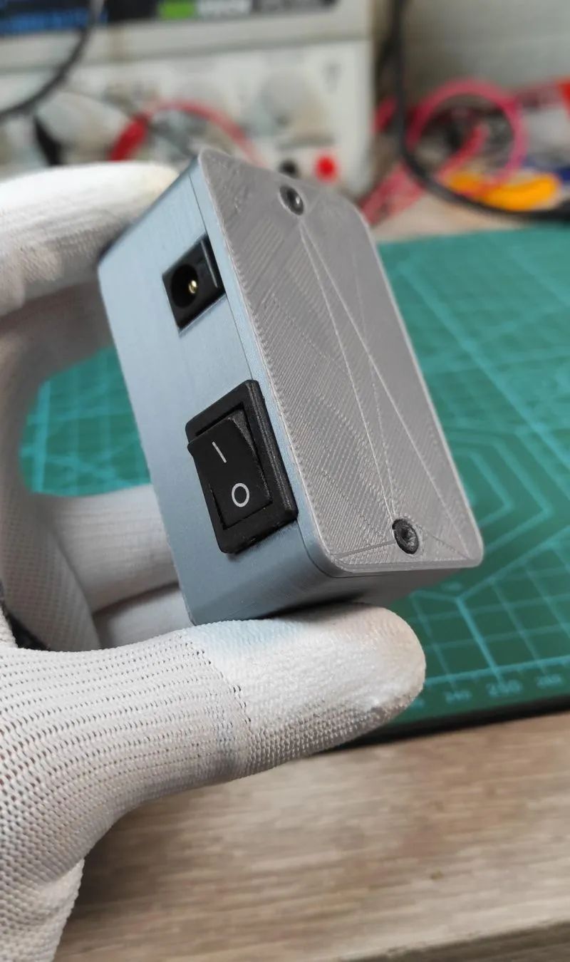 After completion, add the power switch and power connector to the 3D printed bracket, and connect the power line to the cube’s VDD and VSS.
 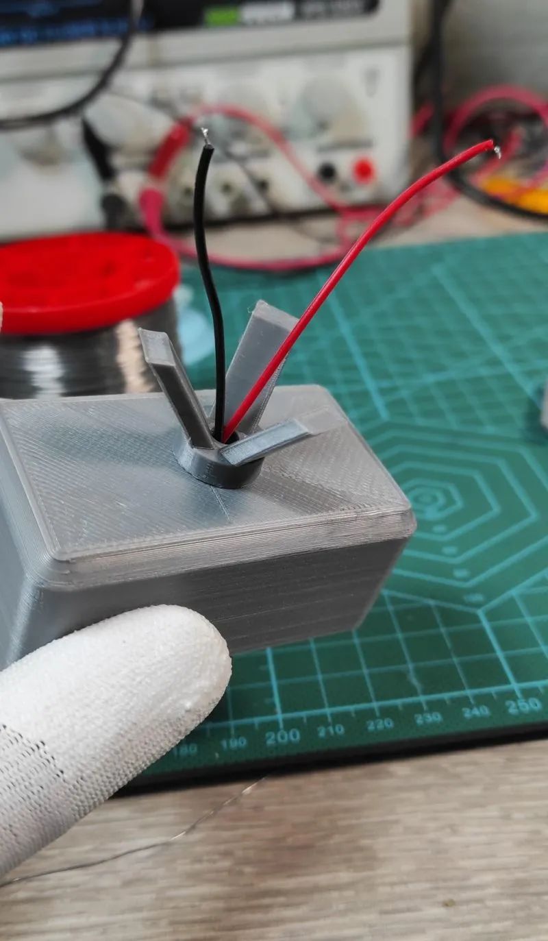 Please ensure that the power adapter can provide 5V 2A current, which may drop to 1.3A when the LED lights are at full brightness.
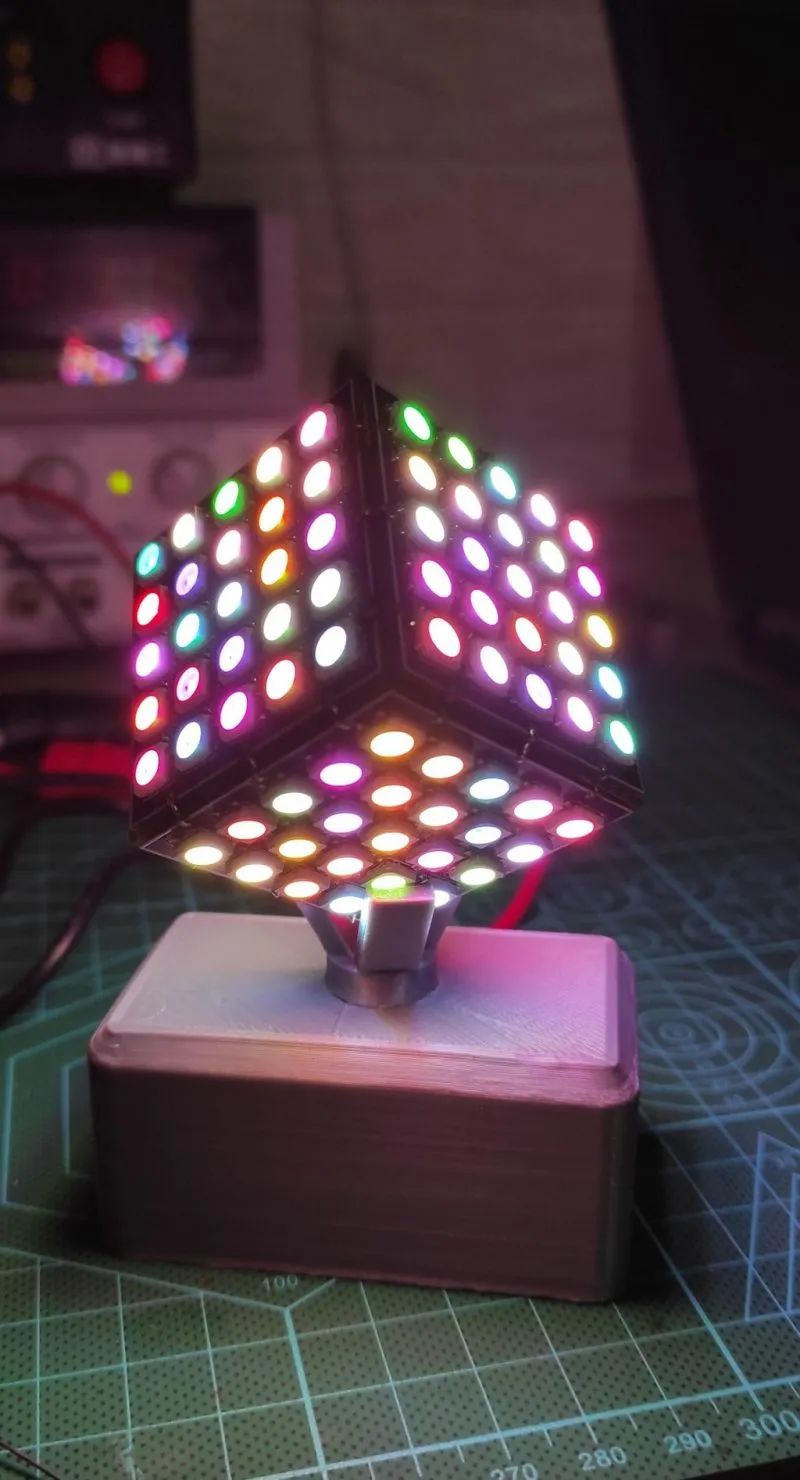
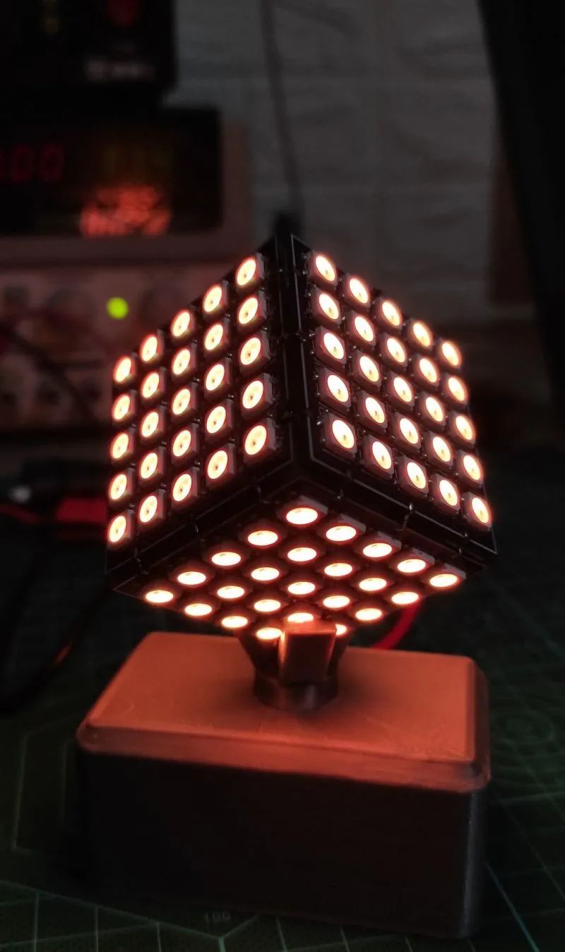
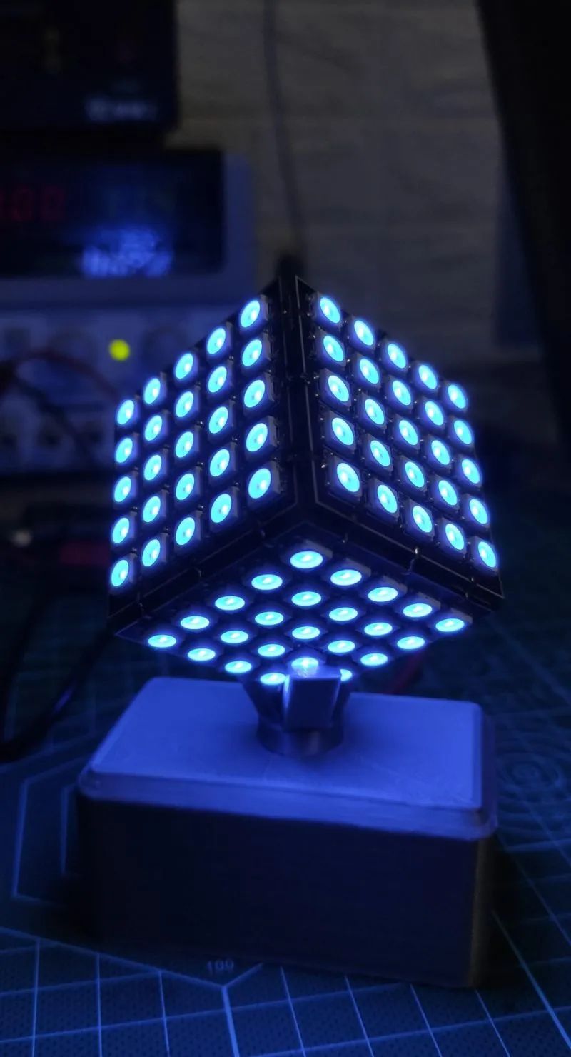 Once all of this is completed, this magical glowing RGB cube is finished. Turn on the switch, and the cube will immediately light up, showcasing a wonderful display of colors.
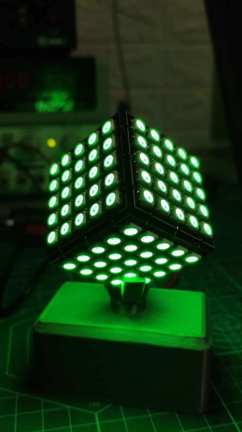
The code used in this project can be downloaded from the project file library: https://make.quwj.com/project/428
via instructables.com/Glowing-RGB-LED-Cube-5x5x5-WS2812/
Links in the text can be clicked to read the original article at the end

More Exciting Content