Click the blue "Arm Selection" in the top left corner and select "Set as Favorite"1. Interrupt Response Model of 51 Microcontroller
Let’s recall the use of interrupts in microcontrollers.
As shown in the figure below, on the left is the pin diagram of the 51 microcontroller, where P3.0-P3.5 are the corresponding interrupt pins. When the level of these pins changes, it triggers a CPU exception. When the CPU encounters an exception (interrupt), it jumps to the exception vector address and executes the handler function, returning afterward.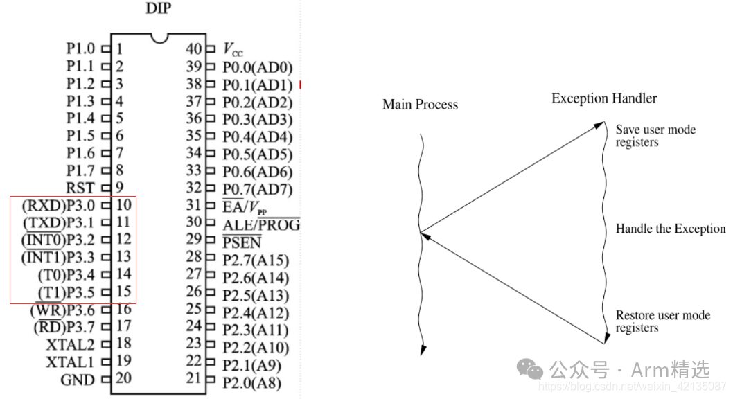 So, when a CPU exception occurs, which address does it jump to? Actually, this is predefined during the CPU’s manufacturing process. As shown in the figure below, the left side shows the base address of the exception vector table designed by the CPU, while the right side shows how software handles exceptions. When a UART interrupt occurs, the CPU triggers an exception and jumps to address 0023, where it executes the LJMP UART0_ISR instruction to handle the interrupt…
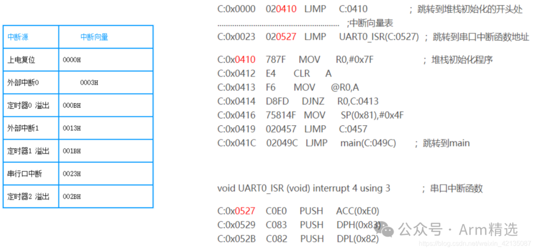
2. What Exceptions Exist in ARM?
-
On ARMV7, ARM exceptions include: RESET, swi, undef, prefetch, data abort, irq, fiq. Among these, RESET and swi are synchronous exceptions, while the others are asynchronous exceptions.
-
On ARMV8, ARM exceptions include: serror, irq, fiq, Synchronous. Here, Synchronous is a synchronous exception, while serror, irq, and fiq are asynchronous exceptions.
What is the difference between synchronous and asynchronous exceptions?
-
Synchronous Exception: Triggered by software actions, and the timing of occurrence is known, e.g., svc, smc, and hyc instructions all trigger synchronous exceptions.
-
Asynchronous Exception: Triggered by hardware or software actions, with an unknown timing of occurrence, e.g., irq interrupts trigger irq exceptions, and fiq interrupts trigger fiq exceptions…
When an exception occurs, the ARM CORE must jump to the exception vector table address. In fact, it jumps to: base address of the exception + offset of the exception vector table.
3. Base Address of ARM Exception Vector Table
(1) The base address of the exception vector table for ARMV7 mainly consists of three registers: VBAR, HVBAR, and MVBAR, where VBAR is banked.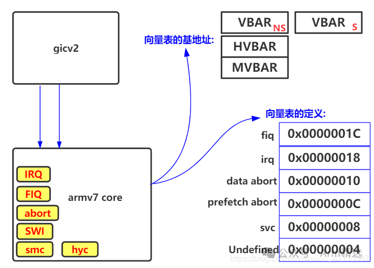 (2) The base address of the exception vector table for ARMV8 mainly consists of three registers: VBAR_EL1, VBAR_EL2, and VBAR_EL3.
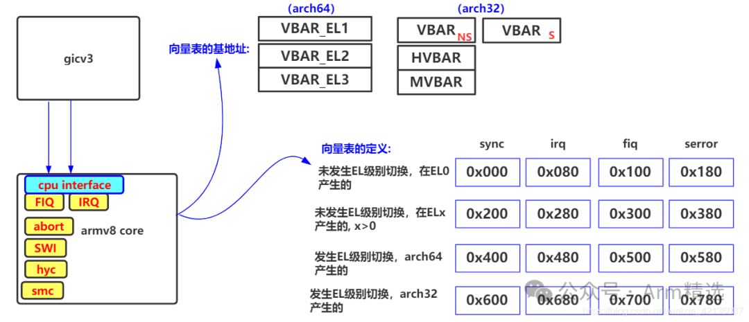
4. Offset of ARM Vector Table
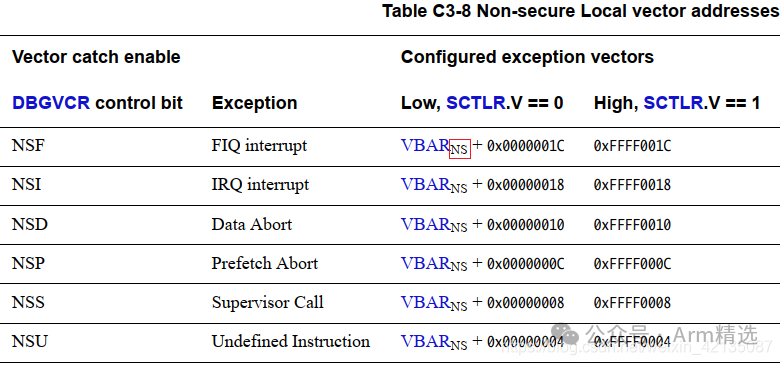
(1) The definition of the exception vector table for ARMV7 actually includes multiple exception vector tables. The figure below lists two exception vector tables on secure and non-secure sides.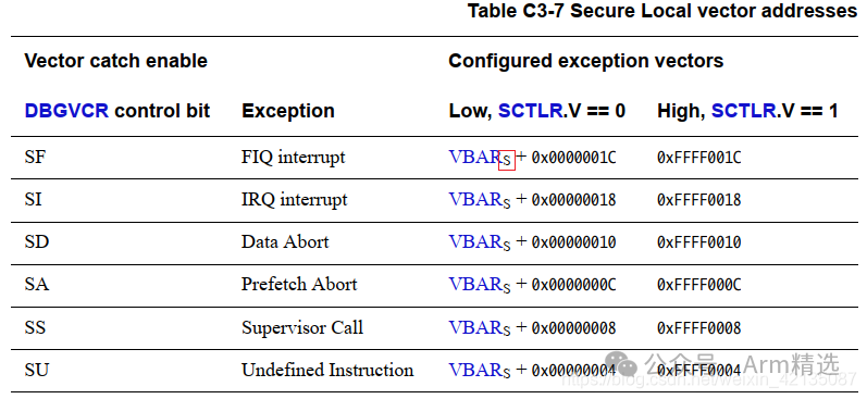
 (2) On ARMV8, the exception vector table actually has four sets of tables, with each set containing four exception entries corresponding to synchronous exceptions, IRQ, FIQ, and error exceptions.
-
If an exception occurs without causing an exception level switch, and the stack pointer used is SP_EL0, then the first set of exception vector tables is used.
-
If an exception occurs without causing an exception level switch, and the stack pointer used is SP_EL1/2/3, then the second set of exception vector tables is used.
-
If an exception occurs that causes an exception level switch and the lower exception level is running in AARCH64 mode, then the third set of exception vector tables is used.
-
If an exception occurs that causes an exception level switch and the lower exception level is running in AARCH32 mode, then the fourth set of exception vector tables is used.
Additionally, we can see that each exception entry no longer occupies just 4 bytes of space, but occupies 0x80 bytes of space, meaning that each exception entry can hold multiple instructions, not just a single jump instruction.


[Store Address]

[Customer Service Consultation]