01
Introduction
Have you ever wondered how we can accurately measure “time”?
You might say, just use a stopwatch, right? But what if we need to measure not in seconds, but in picoseconds (ps) — trillionths of a second? This is not science fiction; in radar, laser ranging, and high-energy physics experiments, precise time measurement down to the picosecond level is commonplace. To achieve a measurement accuracy of 20 ps, traditional “pulse counting methods” (like using a stopwatch) require a 50 GHz clock. If that’s the case, you need to be well-versed in optics and applied physics, so you might want to read this article: “A 49GHz Microwave Q-Band Oscillator Based on Kerr Soliton Crystal Microcombs”; here’s the DOI for your convenience: doi: 10.1109/JLT.2019.2930466.
Today, we won’t discuss advanced physics; instead, let’s talk about how to “count time” using a series of adders and D flip-flops in an FPGA — this is the charm of the Time-to-Digital Converter (TDC).
02
The Domino Effect of Time
Imagine you have a line of dominoes; when you knock over the first one, it will fall one after another. The speed of this “falling” is the “propagation delay” between the dominoes. In an FPGA, adders have a similar “domino effect” — it’s called the Carry Chain. To add two numbers quickly and reliably, chip manufacturers have created a dedicated, ultra-fast “highway” for the carry signals in adders. The delay on this “highway” can be as short as 20 ps!
We design a special series of adders. Normally, when adding 111…111 + 000…000, the result is 111…111, and everything is calm. But at a certain moment, we give it a “Start” signal, prompting it to suddenly calculate 111…111 + 000…001. This small “1” acts like knocking over the first domino, causing a carry signal to propagate from the least significant bit to the most significant bit in a chain reaction. The distance the carry signal travels on the chain represents how much time has passed from “Start” to “now”.
But here’s the problem: how do we “see” where this propagation has reached? The answer is: “take a picture”! We connect a “small camera” (D flip-flop) after each adder, and the shutter of this “small camera” is controlled by another clock signal (which we call the “sampling clock” or Strobe). When the “shutter” flashes, all the “small cameras” simultaneously take a picture, recording which level the carry signal has propagated to at that moment. For example, if the picture shows that the first 10 levels have turned to “0”, we know that from “Start” to the moment of the picture, the carry signal has traveled through 10 levels.
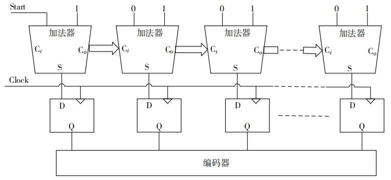
The key question arises: how long is each level of the carry chain? We can use a standard time to measure in advance, for example, by observing how many levels of the carry chain propagate within 1 us, thus obtaining the delay of each level. However, the reality is that the delay of each level is not exactly the same! The carry chain inside the FPGA is not made up of “standard dominoes”. Some blocks are close (within a Slice), while others are far apart (across Slices). What can we do? Don’t worry; we can measure each “domino segment” individually, just like in photogrammetry!
03
Code Density Method: The “Counting Beans” Approach to Time Measurement
We employed a clever method — the code density method, which sounds sophisticated but is essentially like… counting beans! We make the Start and Strobe signals two unrelated clocks with different frequencies (clk_i and clk_d), where the frequency of the photo-taking clock is significantly higher than that of the Start clock (which can be understood as the frequency of resetting the dominoes). We then repeatedly set up, knock down, and take pictures. The purpose of this operation is to ensure that the propagation time for each photo is random, meaning that the time t in the diagram below is randomly distributed in the interval [0, Tc), where Tc is the period of clk_d, or the photo-taking period.
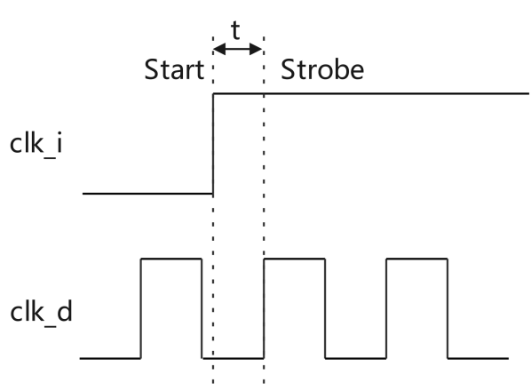
Each time we take a picture, the dominoes only fall to a certain block, and the number of the “last fallen block” is what we care about. We take many pictures, recording how many times each block becomes the last one to fall. The more times a block is hit, the longer its delay — just like the more beans in a bowl, the more “sluggish” it is.
In this way, we obtain the delay distribution of the entire carry chain, akin to marking precise scale lines on the domino chain! Through this method, we can accurately measure the true delay time of each level of the carry chain, whether it is fast or slow. We then store this data in a “lookup table”.
Once we have this “lookup table”, the TDC truly “graduates”; in the future, to measure a time interval, we only need to: give a “Start” signal, take a “snapshot” to get the “level count” of the carry signal propagation, and finally look up the table to sum the delays of each level to obtain the precise time!
04
Summarizing This Clever Trick
1. Replace the TDC’s Start and Strobe signals with two “mismatched frequency” clocks;
2. Take pictures repeatedly, recording the endpoint of the domino (carry chain) propagation;
3. The more times a position is “hit”, the longer its delay;
4. Statistically determine the true delay of each carry unit, forming a lookup table for high-precision time interval conversion.
Tip
(This article is based on the “TDC_DEMO User Guide” from Xi’an Zhiduo Crystal Microelectronics. For those interested in technical details, please visit the Zhiduo Crystal official website for more information.)

Welcome to follow Zhiduo Crystal!
Headquarters in Xi’an:Room DEF101, 1st Floor, Zero One Plaza, 72 Keji 2nd Road, High-tech Zone, Xi’an
Beijing Office:Room 707, 7th Floor, Yiste Building, 15 Xihuan North Road, Haidian District, Beijing
Xiamen Office:Room 801, Building 5, Xinke Plaza, Torch High-tech Zone, Xiamen
Chengdu Office:Room 2402, 24th Floor, Building 1, Angus International Center, 366 Yizhou Avenue North Section, High-tech Zone, Chengdu
Jinan Office:Room 1101, 11th Floor, Building 3, Aosheng Building, 1166 Xinluo Avenue, Jinan Free Trade Zone, Shandong
Shanghai Sales Office:Room 611, Building 19, Fenghuang Garden, 1515 Gumei Road, Xuhui District, Shanghai
Shenzhen Sales Office:Room 3108, East Building, Qiushi Building, 3102 Shennan Middle Road, Futian District, Shenzhen
Technical Support:[email protected]
Official Website:www.isilicontech.com