Today, we will introduce a hardware implementation case of the FRC module. The figure below shows the sub-processing module of this module.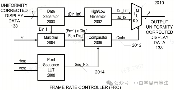
The above figure is the block diagram of the Frame Rate Controller (FRC). One function of the FRC is to overcome certain well-known characteristics of displays, such as undesirable visual artifacts. These artifacts may includevisual flicker and motion blur.
The FRC compensates for the above characteristics by executing static and dynamic dithering to provide continuous intensity within each frame and between frames of display data. Frame Rate Control (FRC) refers to the technique of changing the duty cycle of pixel stimulation on the display to produce different levels of pixel intensity. The results of FRC are commonly referred to as grayscale images, but may also refer to color images. FRC can be performed by limiting the various levels of pixels on the display. Below describes 16-level FRC.
The FRC should include a data separator, High/Low generator, multiplier, comparator, pixel sequence LUT, and multiplexer.
The data separator displays the data. The input corrected display data is 12 bits, meaning it can display 2^12 grayscale levels. However, if the display panel data width is 8 bits, the grayscale difference between two pixels may be much less than 2^8 grayscale levels, which is four thousand grayscale levels. Therefore, traditional methods using 8-bit or 10-bit display data cannot provide sufficient grayscale correction. By increasing the number of frames, such as from 4 to 16, the bit width of the output display data is increased to provide equivalent 12-bit wide display data. All 12 bits of the input display data execute static or dynamic dithering algorithms and reduce the data width of the display data before display by outputting 8-bit dithered display data to match the data width of the source driver. The data separator separates the received display data into the high integer part and the low fractional part. The high part (referred to as Din_int) includes the high 8 bits, while the low part (referred to as the fractional part Din_f) includes the low 4 bits. Then, Din_int is input to the High/Low generator.
The High/Low generator generates the data output high value Do_hi = Din_int + 1 and the data output low value Do_lo = Din_int. The multiplexer receives the Do_hi and Do_lo values and determines which one serves as the 8-bit dithered output.
The multiplier multiplies the fractional part Din_f by the frame counter Fc and multiplies the fractional part Din_f by the frame counter plus 1 (Fc + 1). The multiplied values Fc * Din_f and (Fc + 1) x Din_f (mod((Fc + 1) x Din_f, 16) and (mod(Fc * Din_f, 16)) (or ignore carry and keep 4 bits).
The pixel sequence LUT contains the sequence number patterns and outputs one of the sequence numbers based on the horizontal pixel counter Hcnt and vertical line counter Vcnt values received from TCON.
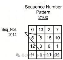
The above figure is an example of the sequence number patterns stored in the pixel sequence LUT. The sequence number pattern includes a 4×4 matrix with 2-bit vertical counting and 2-bit horizontal counting. The sequence number pattern includes 16 storage locations for storing 16 sequence numbers, whose values are preferably within 0 to 15.
Key 1: The sequence numbers themselves are evenly distributed within the pattern LUT.
Key 2: For the dithering pattern between frames, the current point and the next point (or previous point) have the same distance relationship.
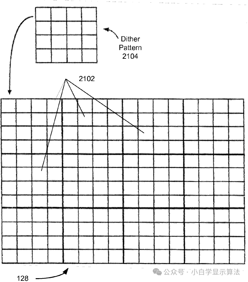
Relationship diagram between flat panel displays and dithering patterns
Displays typically consist of an NxM (horizontal by vertical) pixel array, where N and M can be hundreds or thousands. Dithering is applied to the display in a non-overlapping manner to consider all pixels on the display.
In operation, the 4-bit address accesses the 16 storage locations in the pixel sequence LUT. The 2 LSBs of Hcnt provide the lower 2 bits of the 4-bit address, and the 2 LSBs of Vcnt. Based on the values of Hcnt and Vcnt for each pixel of the display data, the pixel sequence LUT outputs one of the sequence numbers. This sequence number is used to derive 16 different dithering patterns.
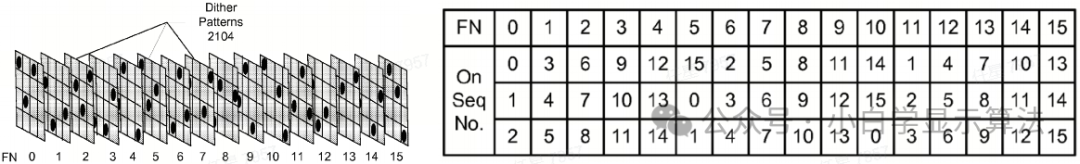
The upper left figure shows 16 dithering patterns, thus creating a constant dithering display in any 4×4 area of the frame of display data and between frames. Each dithering pattern is associated with a frame count Fc numbered from 0 to 15. The frame rate controller can reach 60fps, and the dithering pattern in the upper right figure repeats every 16 frames. Each dithering pattern is a 4×4 matrix, with each block of the matrix representing a pixel on the display. The black dots indicate the pixels that are applied. By storing only the sequence number patterns in the pixel sequence LUT, 16 dithering patterns can be derived with minimal storage. If Din_f = 3 and the frame number Fc is 3, then Fc * Din_f = 3 x 3 = 9, (Fc + 1) x Din_f = 4 x 3 = 12.
The upper right table shows the combinations of sequence numbers in the pattern. The first row is a list of 16 frame numbers from 0 to 15. The second row is the possible values of the multiplier output (Fc x Din_int), such as 0, 3, 6, 9, 12, 15, ignoring carries like 2, 5, 8, etc. This table shows that for frame number 3, a dithering pattern with active sequence numbers 9, 10, and 11 is generated. The comparator uses the upper right table to compare the frame count Fc with the sequence number output from the pixel sequence lookup table. The comparator compares Seq_No with the mod((Fc + 1) x Din_f, 16) and mod(Fc x Din_f, 16) to generate a value of 0/1.
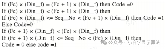
The multiplexer receives the code (0/1) from the comparator and receives the Do_hi and Do_lo values from the High/Low generator. If the output code = 1, the multiplexer selects Do_hi as the 8-bit dithered output. If the code = 0, the multiplexer selects Do_lo as the 8-bit dithered output.
Thus, the introduction of this module is complete.