Based on the working principle and performance characteristics of quadrotor UAVs, the hardware circuit of the flight control system is designed. The system includes a microcontroller module, attitude measurement module, wireless communication module, remote control module, and motor drive module. The system provides a hardware platform for sensor parameter measurement, control algorithm implementation, wireless communication, etc., with low power consumption and high reliability. Experimental results show that this system can operate stably and reliably.
The quadrotor UAV is an unmanned aerial vehicle with 6 degrees of freedom and 4 control inputs, capable of vertical takeoff and landing, hovering, forward flight, lateral flight, and backward flight. The four rotors can cancel each other’s torque, eliminating the need for specialized anti-torque propellers. It is widely used in fields such as unmanned reconnaissance, forest fire prevention, disaster monitoring, and urban patrols. The flight control system is the core part of the quadrotor UAV, and its performance determines the overall system performance. In recent years, the autonomous flight control of miniature quadrotor UAVs has gained widespread attention from researchers. With the development of computer technology and electronic technology, the research and development of small UAVs in China has gradually heated up, and many companies have formed an industry. For example, DJI has commercialized quadrotors and other multirotor UAVs. The focus of domestic research is mainly on three aspects: attitude control, sensor technology development, and the application of new materials and battery technology research. Typical representatives include Harbin Institute of Technology, Beihang University, Nanjing University of Aeronautics and Astronautics, and National University of Defense Technology. In terms of control algorithms, advanced PID control is widely used.
The system hardware circuit is designed using the ARM Cortex-M3 architecture STM32C8T6 as the flight control processor, MPU-6050 as the attitude sensor, low-power 2.4GHz nRF24L01 as the wireless transmission device, and HC-RS04 ultrasonic as the obstacle alarm sensor. After experimental debugging, the hardware system can operate stably and reliably.
1 Overall System Structure Design
Physical Structure Design
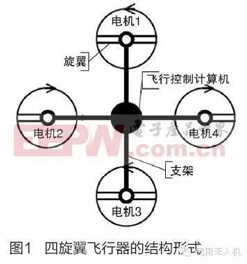
The quadrotor UAV consists of a cross frame and four propellers. The flight control processor and external devices are placed in the middle of the frame, and the four propellers have the same radius and angle, symmetrically arranged in the left, right, front, and rear directions. The four motors are symmetrically mounted on the ends of the frame, where motor 1 and motor 3 rotate counterclockwise, and motor 2 and motor 4 rotate clockwise. The operating state of the motors is controlled by changing the speed of the four motors. Its structural form is shown in the figure.
Working Principle
When the quadrotor UAV is operating, it adjusts the speed of the four motors through the motor speed control system to achieve different changes in lift, thereby controlling the operating state of the UAV. Motors 1 and 3 rotate counterclockwise, while motors 2 and 4 rotate clockwise, canceling the gyroscopic effect and air torque effect, ensuring that the UAV can fly in a balanced and stable manner. By appropriately changing the speed of the motors, the flight state of the UAV can be controlled.
Overall System Design of the Flight Control System
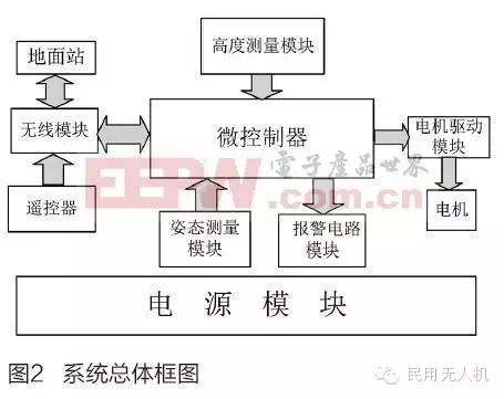
The flight control system is divided into ground and onboard parts, which are physically separate but logically connected. The ground part is further divided into ground station and remote control parts, which are independent of each other. The entire flight control system consists of a microcontroller module, wireless module, motor drive module, attitude measurement module, altitude measurement module, alarm circuit module, ground station, and remote control, among others. The overall block diagram of the system is shown in the figure.
2 Main Functional Module Hardware Circuit Design
Microcontroller Module
This control system is a multi-input multi-output system, where the main input signals of the control module are measurement data from various sensors, and the output signals are four pulse-width modulated motor control signals, requiring multiple timer/counter control signals for pulse width. The system needs to process a lot of data from sensors and needs to send data back to the ground system, requiring real-time control and fast response speed. In addition, the sensor interfaces of this system are diversified, requiring more diverse interfaces for easier software reading. Based on these requirements, the flight controller microprocessor module is selected as the ARM Cortex-M3 core STM32F103C8T6, which has a clock frequency of up to 72MHz and has IIC bus interface, JTAG interface, SPI interface, AD acquisition interface, multiple PWM outputs, and multiple serial ports, facilitating the connection of diverse sensors and the downloading and debugging of programs. This microcontroller has 8 timers, which can meet the requirements for signal acquisition and PWM output.
Attitude Measurement Module
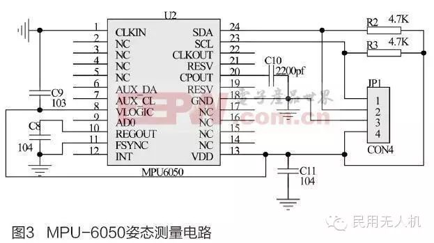
The quadrotor UAV is greatly affected by motor vibrations and external interference, making it difficult to establish an accurate mathematical model, and its payload is limited. Generally, inertial devices are used as attitude measurement devices, and the attitude measurement component is an important part of the entire hardware system. This design comprehensively considers hardware design principles and uses MPU-6050 as the attitude sensor for the UAV. MPU-6050 communicates through the IIC protocol interface, only needing to connect the SDA data line and SCL clock line of the MPU-6050 to the general I/O ports of the STM32, as shown in the circuit diagram. To stabilize the output and avoid idle bus leakage, R2 and R3 are used as pull-up resistors for SDA and SCL, enhancing the load capacity of the bus. In the circuit, C9 is the digital power supply voltage filter capacitor, C8 is the calibration filter capacitor, C10 is the charge pump capacitor, and C11 is the power supply voltage filter capacitor.
Wireless Communication Module
The system requires wireless communication in three aspects: first, it needs to send signals from the remote control through the wireless module. Second, the ground station needs to receive attitude data from the flight control end and send control parameters. Finally, the flight control end needs to receive data from the remote control and ground station. Considering communication distance, cost, and other factors, this design selects the nRF24L01 wireless module device. Its transmission circuit can be constructed using an LC oscillation circuit. To facilitate maintenance, the wireless module is made independent through an interface.
Remote Control Module
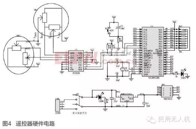
This design adopts a joystick control method, using a digital-to-analog converter to convert the joystick’s analog signal into a digital signal, which is then transmitted to the small controller after certain data processing, and sent out wirelessly for the UAV controller to receive and utilize. The nRF24L01 is used as the wireless transmitter for the remote control. To facilitate digital-to-analog conversion, the joystick uses a joystick potentiometer, measuring the remote control’s travel by collecting the potentiometer’s voltage value; since the remote control processes a single signal and does not require a high-speed processor, an 8-bit 51 microcontroller STC89C52RC is used as the controller for the remote control, to collect the joystick’s analog signal and send the collected data. The PCF8591 is used as the data acquisition device, which has 4 analog input channels and 1 analog output channel, belonging to standard IIC communication, meeting the requirements of this design. The hardware circuit of the remote control is shown in the figure.
Ground Station Module
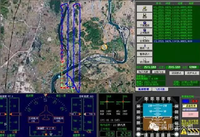
The ground station of the UAV mainly completes the following two functions: (1) Detecting the flight status of the UAV during stable flight and passing control parameters to the UAV to make it operate according to the control algorithm; (2) During the debugging phase of the UAV, completing the modification and adjustment of the UAV’s PID parameters. Since the PC generally leaves USB interfaces for user operations, while the nRF24L01 communication interface is SPI, this design uses a 51 microcontroller to read data from the nRF24L01, and the microcontroller continues to communicate with the PC through a USB-to-serial chip to complete the data transmission function of the ground station.
Motor Drive Module Motor Drive Principle
This design selects a brushless DC motor as the power drive device for the UAV. According to the commutation principle of brushless DC motors, the control forms of brushless DC motors are divided into: open-loop control, speed negative feedback control, and voltage feedback plus current positive feedback control. Among them, open-loop control does not have feedback correction, suitable for places where speed accuracy is not high; speed negative feedback control has good mechanical performance; voltage feedback plus current positive feedback control is generally used in occasions requiring high dynamic performance. For this design, real-time adjustment of motor speed is needed, and the speed adjustment frequency is relatively high, so this design adopts the voltage feedback plus current positive feedback control method.
Motor Drive Circuit Design
Based on the motor control principle, the motor drive circuit is divided into three parts: microprocessor, back electromotive force detection, and power drive part.
(1) Microprocessor
Due to the high commutation frequency of brushless DC motors, it is not suitable to use low-frequency processors. Moreover, the rotation of the motor generates a rotating magnetic field, which greatly interferes with the processor. After comparison, this design selects the ATMEGA8 microcontroller as the motor drive microprocessor.
(2) Back Electromotive Force Detection
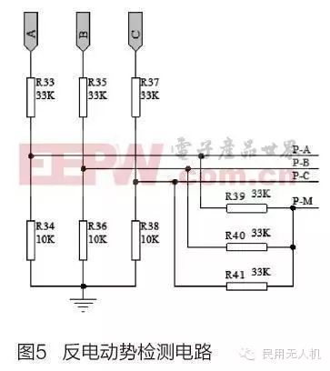
During the commutation process, it is necessary to continuously detect the position of the rotor. The back electromotive force generated by the rotor can indicate the rotor’s position information. By applying the voltage divider attenuation principle, the voltages of the three-phase back electromotive force relative to the neutral point are detected to determine the rotor’s position. The back electromotive force detection circuit is shown in the figure.
Where A, B, C terminals are the three-phase voltages of the motor, and R33~R38 are the voltage divider resistors. P-A, P-B, P-C are the voltages corresponding to the three-phase back electromotive force, and P-M is the neutral point voltage.
(3) Power Drive
The power drive is to provide large current to the motor to achieve stable operation. This design uses parallel MOSFETs to increase the output current, connecting three P-channel MOSFETs in parallel at each phase’s upper bridge arm to achieve controllability of the three-phase full bridge, and also connecting three N-channel MOSFETs in parallel at each phase’s lower bridge arm.
3 Hardware System Debugging
PWM Control of UAV Drive Motor Debugging
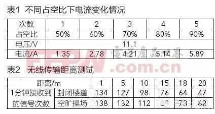
By powering the four motors and applying PWM waveforms with different duty cycles to control the motor speeds, the changes in power supply voltage and current are recorded. Under stable output of 11.1V, the power supply current changes under different duty cycles are shown in Table 1.
From Table 1, it can be seen that the greater the duty cycle, the greater the current required for the motor drive to operate; when the duty cycle approaches the limit value, the current output changes very little. The experiment shows that the hardware system can operate reliably.
Wireless Communication Debugging
By testing the wireless connectivity, transmission distance, and packet loss rate, the performance characteristics of the wireless module are determined. The remote control is set to transmission mode, and the ground station is set to reception mode, using the ground station’s alarm light to indicate the reception status. A successful reception results in a flash. By changing the distance between the remote control and receiver, the number of times the indicator light flashes within a minute is recorded to evaluate the quality of wireless transmission; tests are conducted in the corridor of a teaching building and an open playground, with detailed records shown in Table 2.
From Table 2, it can be seen that the transmission effect of wireless communication significantly decreases after 15m, which is determined by the power of the wireless communication module. The experiment shows that the wireless communication part can operate reliably within the design requirements.
Comprehensive Debugging

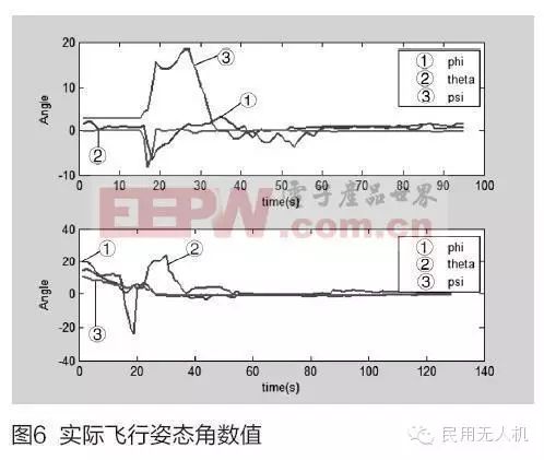
Figure 6 shows the attitude curve of the quadrotor UAV controller after downloading the PID control algorithm for actual flight control, where ① represents the roll angle, ② represents the pitch angle, and ③ represents the yaw angle. Figure 6 shows the angle data of the UAV after being disturbed by crosswinds, where the attitude angle is controlled to reconverge to a stable (0,0,0) state. The figure below shows the angle data of the UAV converging from a certain attitude to a stable (0,0,0) state. From the experimental results, it can be seen that the system can operate stably.
Conclusion
The design of the quadrotor UAV control system scheme and the selection of hardware components and circuit design for each module have been completed, and the debugging of the system hardware circuit has been carried out. Experimental results show that the system can operate stably and reliably.
This article is sourced from: Electronic Products World
Article Author:Feishou Community
Daily updates on drone news and insights!
Long press the QR code to follow us!