1IntroductionImagine if the MCU we work with only runs bare-metal programs; when it reaches a thread that includes a delay, our CPU would start to “idle”.To maximize CPU utilization, we need to use an RTOS (Real-Time Operating System). In simple terms, an RTOS is an operating system that schedules all available resources to complete real-time tasks and controls all real-time tasks to run in coordination, or in other words, its kernel is a framework for task management.
There are many excellent RTOS options available on the market, such as FreeRTOS, Zephyr, RT-Thread, etc. Many newcomers may feel intimidated by the thick accompanying books or the large codebases when first encountering RTOS, but there is no need to fear. Learning while building your own RTOS, like a chef skillfully preparing a dish, is a great way to learn. Let us embark on the journey of learning RTOS! 
Figure 1 RTOSVersion
Just like building a tall building, one must first survey the terrain and ensure a solid foundation before gradually adding bricks and tiles.Building an RTOS follows the same principle; we need to understand the architecture it runs on. Taking NXP’s RT series chips as an example, we need to learn about the ARM Cortex-M series architecture.This is a very large system, and I recommend the “Authoritative Guide to ARM Cortex-M3 and Cortex-M4” as a good reference book. The following will list the most core content needed to build an RTOS.  Figure 2 “Authoritative Guide to ARM Cortex-M3 and Cortex-M4”
2ARM Processor Architecture Related Content
2.1 Operating Modes and States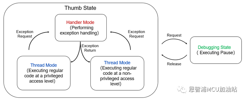 Figure 3 Operating Modes and States
The Cortex-M series has two operating states and two modes, which can distinguish between privileged and unprivileged access levels.The debug state only takes effect when connected to a debugger; if the processor is executing program code, it is in Thumb state. The Cortex-M processor does not support ARM state, so ARM state does not exist.
The two modes areHandler ModeandThread Mode:Handler Mode is used for exception handling and always has a privileged access level; when executing normal application code, the processor is in Thread Mode, which may be in either privileged or unprivileged access level. The former can switch to the latter, but switching from the latter to the former requires using the exception mechanism.
2.2 RegistersThe Cortex-M processor has multiple registers in the core for executing data processing and control, most of which are grouped in register banks. Taking the Cortex-M4 processor as an example, there are 16 registers in the register bank. Figure 4 Registers in the Register BankAmong them, R0-R12 are general-purpose registers, R13 is the stack pointer used for stack storage access. Physically, there are two stack pointers: the Main Stack Pointer (MSP) for Handler Mode and the Process Stack Pointer (PSP) which can only be used in Thread Mode. R14 is also known as the Link Register, used to save the return address during function or subroutine calls. R15 is the Program Counter. In addition to the registers in the register bank, there are also several special registers in the processor. Below are a few typical special registers:
 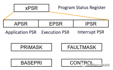 Figure 5 Special RegistersAmong them, the Program Status Register contains three status registers used to save processing status information. The PRIMASK, FAULTMASK, and BASEPRI registers are used for exception or interrupt masking, while the CONTROL register is used for stack pointer selection and access level in Thread Mode.2.3 Vector Table and System Control Block
When the Cortex-M processor receives an exception request, it needs to determine the starting address for handling that exception, which is located in the vector table in memory. The core exception used in building RTOS is PendSV, which has the lowest priority and can be interrupted by other interrupts, so it is usually used for context switching, that is, task switching. Figure 6 Interrupt Vector Table
The System Control Block (SCB) contains several registers for interrupt control, one of which is closely related to RTOS: the Interrupt Control and State Register (ICSR). By enabling bit 28, we can trigger the PendSV interrupt exception we need.
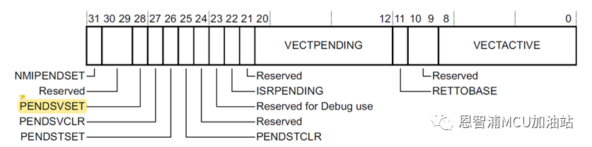 Figure 7 Interrupt Control and State Register (ICSR)
3Implementation of Task Switching
The background knowledge mentioned above is distilled content for building an RTOS. The author suggests that during the development and learning process, one should proceed with questions in mind, learning and expanding simultaneously.Now we can implement the most basic function of RTOS—task switching.First, we need to know that, unlike bare-metal programs, each task in an RTOS has an independent context environment. When a task switch occurs, the state data of each task must be saved, so each task needs to be equipped with its own stack space.
When a task switch is triggered, the current task’s execution must first be paused, and the current task’s state data must be saved to the corresponding stack space. Then, the stack pointer is updated to the stack space of the target task, and finally, the state data is restored from that stack space, thus completing the task switch.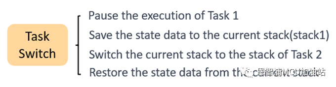 Figure 8 Steps of Task Switching
It is important to note that when the PendSV exception is triggered, the hardware system automatically saves the xPSR, LC, R12, R3-R0 registers, while the pushing of R11-R4 needs to be implemented in code.In addition, during task initialization, the stack space also needs to be initialized, and when the system runs the first task, there is no need to perform stack pushing. Therefore, it is necessary to determine whether the task is the initial task. A relatively simple method is to set the PSP to 0 before running the initial task for judgment, but this can have a certain impact on system running efficiency. More mature RTOS implementations have more clever handling methods, which interested readers can look up themselves.
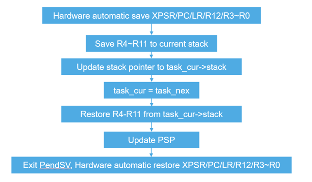 Figure 9 Context Switching Process
With this implementation, the foundation of an RTOS has been laid. Please continue to look forward to the next part where we will learn about: priority lookup, priority inversion, critical section protection, and thread synchronization functions in detail!