🏷️GNURadio is a digital signal processing development environment, similar to Matlab Simulink or LabView
🏷️Modular, allowing specific functionalities to be achieved simply by connecting these modules
🏷️Includes codec modules, demodulation modules, hardware interface modules
🏷️As well as time domain display modules and frequency domain display modules
🏷️The entire project is open-source, allowing access to the internal code of the modules
The flowchart below shows the reception of a 433.9MHz signal, observed in the time domain
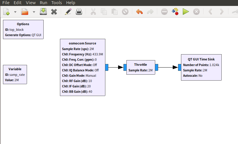
Since the hardware module has completed the down-conversion to baseband, what you observe is the baseband signal or the envelope of the original signal. However, due to the frequency offset between the transmitter and receiver, you may also see some lower frequency sine wave carriers.
Before running, we can also set the time domain display module (oscilloscope module) on the far right.
Set the trigger to normal mode and configure it for rising edge triggering, with a trigger level of 0.5. This way, the screen will only refresh when a signal that meets the requirements appears. If you click run at this point, the interface will look like the image below, and since there are no waveforms that meet the requirements, the interface is empty.
At this point, transmit a 433MHz signal using a car key, and the waveform will display on the screen. Unlike a regular oscilloscope, the trigger moment is displayed on the far left of the screen rather than in the center.
To achieve a display style familiar to oscilloscope users, set the delay to 300us, which is 0.003s.
Then you will get a waveform similar to the one below
Currently, the display modules in GNURadio are all implemented using QT, hence they are referred to as QT-GUI. Older versions may still have WX-GUI, but it is rarely used now; it is recommended to refer to QT-GUI as a reference.
We previously debugged the triggering function related to the oscilloscope, which is a time domain instrument, so the corresponding module is called time_sink. Here, sink means the destination of the signal; it means that when the signal is sent to it, it can display the signal in a time-based manner.
Specific code location:
https://github.com/gnuradio/gnuradio/blob/main/gr-qtgui/lib/time_sink_f_impl.cc
In subsequent articles, we will gradually analyze the above code.