Using Verilog, an RTL-level design of a motor control system for two motors with encoders has been implemented in an FPGA.
Introduction
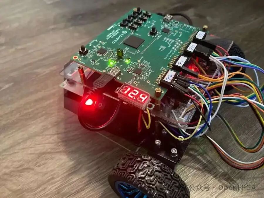
With the help of the hardware description language (HDL) Verilog and the AMD Vivado design suite, an RTL design of a controller system for two motors with encoders has been implemented in the AMD Spartan-7 FPGA.
In this project, a Spartan-7 FPGA development board is used as the motor controller system.
Before starting the project, one might ask, “Since programming with an MCU is much simpler and faster, why use an FPGA for such a complex task?” This is a good question. Therefore, we will briefly explore the various reasons why people choose FPGAs.
After comparing FPGAs with MCUs, we will introduce basic concepts such as motor drivers, H-bridges, PWM, encoders, PID feedback control systems, encoding and testing, and data collection analysis. Then, we will detail how to build your own FPGAbot.
FPGA vs. MCU
Selecting the “best” processing technology for a specific product or deliverable system is crucial to its success in many ways. Factors include support costs, supply chain, profitability, lifespan, etc. From an engineering perspective, the most influential typical factors in decision-making are time, cost, area, and power consumption.
Advantages of FPGA
FPGAs are known for their low latency, inherent parallel processing capabilities, and flexibility. Additionally, FPGAs can provide high determinism and precise timing/delay for many independent computing modules, external sensors, and actuators. Therefore, FPGAs are found in many critical task applications, such as:
1) Military and Aerospace Systems
Radar systems – for example, real-time (RT) signal processing and data acquisition. Unmanned Aerial Vehicles (UAVs) – for example, flight control, sensor processing, and secure communication.
Aerospace electronics, satellites, missile guidance systems, etc.
2) Industrial Control Systems (ICS)
Real-time control and monitoring of critical infrastructure such as power grids and refineries.
Industrial automation – machine control, enabling fault detection, redundancy, and fault-tolerant control.
Functional safety – for example, fault-tolerant systems in automotive and industrial control.
3) Medical Devices
Diagnostic imaging systems – fast and accurate data processing.
Patient monitoring – FPGAs provide high-performance, RT monitoring, and signal analysis for patient monitoring devices.
Life-saving devices…
ETC.
4) Telecommunications, etc.
Many critical task applications require real-time processing, deterministic behavior, low latency, programmability, parallel processing capabilities, security, and power efficiency.
Advantages of MCU
For cost-sensitive products or general hobbyists, MCUs are a better choice for cost savings and faster system development turnaround.
Microcontrollers use standard programming languages for software development, such as Python/microPython and C/C++. The learning curve for FPGA design (architecture, hardware description language, timing issues, etc.) is much steeper and requires a significant investment of time and experience to complete efficiently.
MCUs are also better suited for peripheral interfacing and executing repetitive tasks. The general architecture, serial execution flow, and ease of peripheral integration make MCUs more attractive in non-critical task systems.
Having understood this, let’s dive into the details of the mobile robot motor control system!
Advanced Motor Controller System Design
This section introduces the main external components required for the mobile robot motor controller design and the FPGA functional modules. Additionally, a high-level schematic of the system is provided.
Motor Driver
The FPGA needs to drive two 12V DC brushed motors separately. I have previously used 12V DC motors and found that this voltage level meets the torque requirements for my DIY robot. I usually choose low-speed motors (e.g., 190 RPM) because they provide greater torque than high-speed motors.
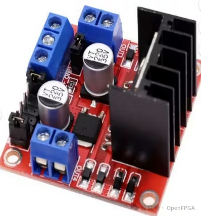
The L298N H-bridge motor driver is an excellent choice for driving 12V motors because it is inexpensive, and many hobbyists have written articles about its use, making it easy to connect.
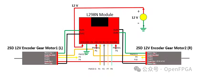
The L298N is essentially an amplifier whose digital interface is controlled by a smaller input control voltage (e.g., 3.3V or 5V) and produces a proportional output across a larger DC voltage range. The L298N module can operate within a DC voltage (Vs) range of 5 to 35V. Since we are using a 12V DC motor, the source voltage is 12V, as shown in Figure 1.
Note: If you want to enable the onboard 5V power regulator of the L298N, the maximum input DC power supply should not exceed 12V. Otherwise, the 5V DC regulator will overheat and shut down.
Encoder
I always purchase DC motors equipped with Hall effect sensors. These sensors can measure the speed and rotation direction of each motor. In this design, encoder feedback is used for the PID algorithm to keep the FPGA robot moving straight and stable. Mileage can also be calculated based on this information. The working principle and usage of the encoder will be discussed in detail in the technical review section and the FPGA motor controller design details section later.
Therefore, the system requires at least the following functional elements:
Top-level architecture
-
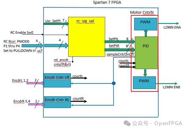
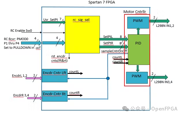
Option (1) can use pulse width modulation (PWM) on the enable pin and control direction through high and low logic levels on IN1, 2, 3, and 4 (Figure 2a); or (2) use PWM on all four input ports and set the enable pin to a logic high level (Figure 2b). Although both versions have been created, option (1) will be chosen in this project description (Figure 2b). The reason for choosing option (1) will be explained in the L298N section.
-
Input setpoint (PWM duty cycle setting) and rotation direction source signal selector.
-
Encoder counter.
-
PID feedback control system/algorithm to synchronize motor speed to the setpoint.
-
Digital controller, in this case, the Spartan-7 FPGA.
For the first two points listed above, understanding how the L298N works is very helpful for the logic required to generate the PWM signal from the setpoint. Therefore, the next section (optional reading) will cover this part and other background knowledge.
Technical Review
This section will technically review the components and introduce the digital and analog concepts required to interface with these components. The information covered in this section is not a prerequisite for executing this project but helps understand the reasons for creating various modules and logic.
L298N Motor Driver
As shown in Figure 3, the L298N can be classified as a DC amplifier that converts pulse width modulation (PWM) signals at its input, in this case, 0 and 3.3VDC, and proportionally converts them to a stable 0V DC voltage to Vs, as previously described.
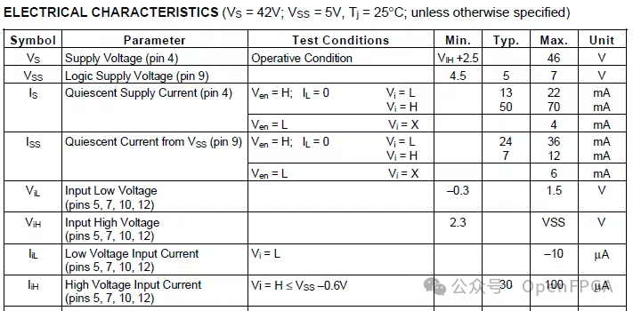
The lower output voltage of the FPGA (0 – 3.3V) can drive TTL logic inputs (IN1 – IN4) and enable A and B due to the specifications listed in [1] and the specifications shown in Figure 4b. These are specified as follows:
Control signal input voltage range:
- Logic low level: -0.3V ≤ Vin ≤ 1.5V
- Logic high level: 2.3V ≤ Vin ≤ Vss
Where Vss is powered by the onboard 5V DC regulator of the L298N module. Since the FPGA does not receive digital data from the L298N, a logic level converter is not required.
The L298N module is built on the L298 integrated circuit (IC). The L298 IC is a high-voltage, high-current dual full-bridge driver. The rated voltage of the L298 IC is Vs = 5V to 46V (Figures 2a and 2b), but the L298N module has thermal and component limitations at voltages above 35V.
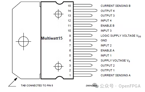
L298 Dual H-Bridge
Let’s take a quick look at the H-bridge circuit. If you do not fully understand the information below, do not worry, but for completeness, I would like to add this. Additionally, if you wish, you can skip this section.
Figure 5 is a copy of the L298 block diagram from [1]. The diagram shows a mix of digital circuits (AND gates and NOT gates) and analog circuits (BJT transistors and resistors). The logic gates and BJT transistors form the current control circuit. To better understand the overall function of the current control circuit, a simplified version of the diagram and its explanation are provided below.
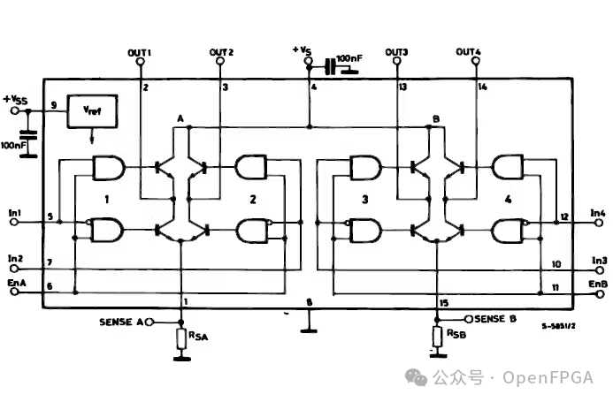
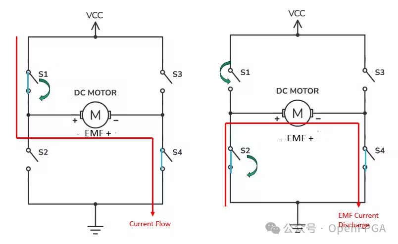
Figure 6 replaces the current control circuit with switch concepts. This demonstrates how the H-bridge circuit works, and we will also use it to explain the difference between using PWM on the IN pins and the EN pins.
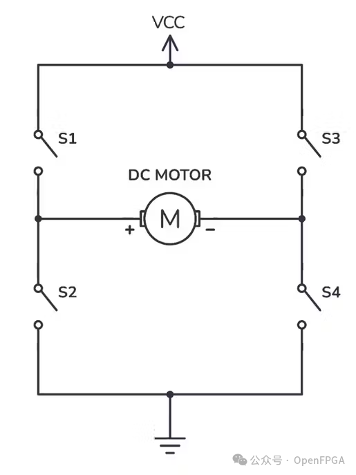
To make the motor rotate forward, S1 and S4 need to be closed, completing the circuit from Vs through the motor to ground (i.e., the current path). S3 and S2 should remain open as needed. To reverse the motor, the opposite situation is required, i.e., closing S3 and S2 while opening S1 and S4. Figures 7a and b illustrate this concept.
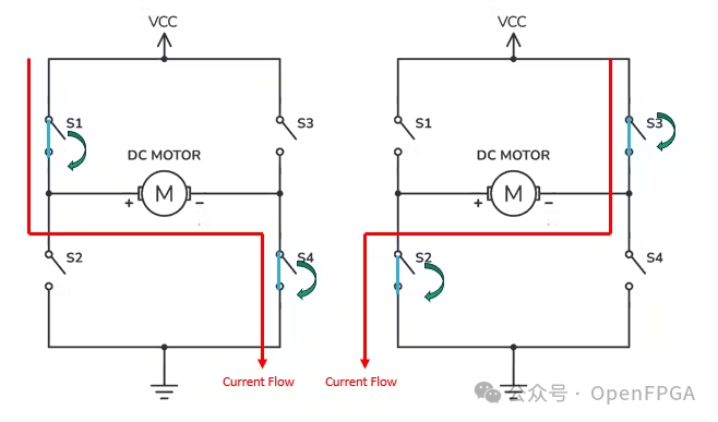
Linking this circuit analysis with Figure 6, let’s look at the switches implemented with logic gates and BJTs. The following logic equations are equivalent to the output of the AND gate, which we will label as _d (representing digital).
- SW1_d = IN1 AND ENA
- SW2_d = NOT IN1 AND ENA
- SW3_d = IN2 AND ENA
- SW4_d = NOT IN2 AND ENA
When any of the above SWx_d equals a logic high level, the corresponding BJT turns on. This is achieved through base-emitter forward bias (Vbe exceeding the threshold of +0.7V drop between the base input and emitter output pins). When the collector voltage is significantly greater than the base and emitter voltages (Vc >> Vb > Ve), the conducting transistor acts like a closed switch. See Figure 8.
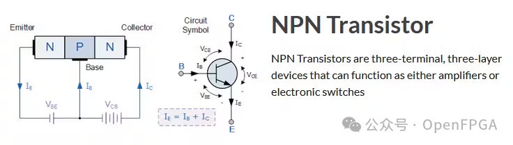
I hope the switch analogy simplifies the control logic of the digital transistors. If interested and with the relevant background knowledge, I recommend finding a good book or reference material to further understand how transistors work and the different types of transistors.
Next, if you need a refresher on PWM, let’s quickly review it. If not needed, you can skip this part.
PWM
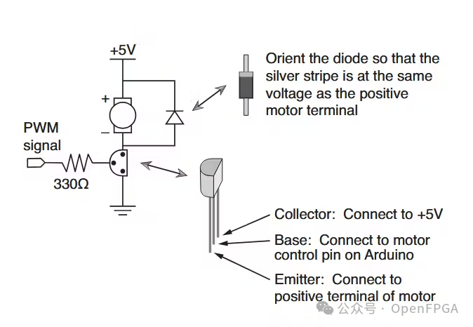
To achieve variable speed for the motors connected to the L298N motor driver, we used PWM (Pulse Width Modulation). PWM is a digital method of obtaining a variable analog voltage. Therefore, the duty cycle of the square wave digital signal (the ratio of the time the logic high level is on to the total pulse period) can be varied to change the average voltage in the analog circuit (Figure 9). For example, if the base-emitter junction of the NPN transistor is on for a longer time during a given period, the current will be larger, resulting in a greater voltage drop (Vce) between the collector output and the emitter (in this case, ground). Figure 10 demonstrates this concept [7].
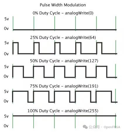
L298N PWM Input Response Characteristics
As mentioned at the beginning of this article, there are two different methods to achieve variable speed using PWM. Method 1 is to drive the input pins (IN1, 2, 3, and 4) with PWM and set the enable pin to high, as shown in Figure 11a. Method 2 is to set the input pins to high and low for the correct rotation direction and drive the enable pin with PWM to achieve variable speed, as shown in Figure 11b.


Using Method 1 will yield the current shown in Figures 7a and 7b. The only difference is the time the current flows from Vs to Gnd during each pulse period.
Using Method 2 will yield a slightly different response. If the motor is driven to rotate forward, the PWM signal on IN1 will be active while the PWM signal on IN2 will remain low. Since ENA has been set to a logic high level via a jumper, the switch toggling is entirely controlled by the valid PWM signal on IN1. Once IN2 and ENA are both set to controlled stable values (0 and 1), SW3 is always set to “off” or “on,” and SW4 is always set to “on” or “off.” However, the NOT gate for SW4 (~In1 and EnA) will open SW2 during the low level of the PWM duty cycle. This occurs when SW1 is in the “off” or “on” state. Therefore, the positive and negative terminals of the motor are connected to ground. This will cause the reverse induced electromotive force (EMF) to be released when SW2 is in the “on” state. This configuration is useful at lower speeds, but at higher speeds, it leads to higher current consumption due to the repeated loss of reverse EMF voltage.
12V DC Encoder Gear Motor
The DC motor we selected for the mobile robot is specifically equipped with a magnetic encoder. This is common for such DC motors. DC motors that require higher control precision use optical encoders.
The rotating magnetic encoder has two Hall effect sensors. They are placed at a 90-degree angle relative to the motor axis. Figure 13 shows how this arrangement produces encoder signals with a 90-degree phase difference.
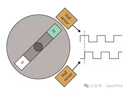
This diagram is simplified as it only uses two magnetic poles. Most motors with magnetic encoders have dozens to hundreds of such magnetic poles, which increases the resolution of the motor’s rotational position. Additionally, some systems are equipped with four Hall sensors for further precision.
The two signals generated by the Hall effect sensors shown above are designated as channel A and B. These channels have the following characteristics:
- They have a phase difference of 90 degrees (see Figure 14).
- If A leads B, then the motor can only rotate in one possible direction.
- If B leads A, then the motor’s rotation direction is opposite to that of the previous bullet.
- The frequency of the square wave is proportional to the rotational speed of the gears.
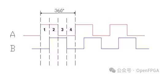
By calculating the number of pulses generated by a single rotation of the motor, the resolution obtained from the physical pole count can be derived. This information can be used to estimate the mileage of the robot by using the accumulated count (which I like to call “tics”) to count/rotation and using the diameter (or radius) of the wheels to calculate its circumference.
FPGA Motor Controller Design Details
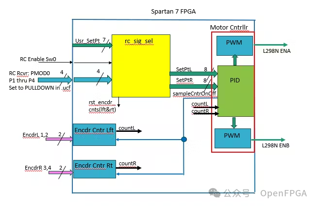
This section will detail the key Verilog code for the mobile robot motor drive system. For convenience, this code will be associated with the system block diagram shown in Figure 2a and replicated in Figure 15 below. Additionally, the PID algorithm I derived can serve as a lead-follow motor speed comparison system and will be explained in detail.
Verilog Source Hierarchy
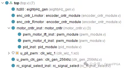
From the initial top-level design shown in Figure 15, a Verilog module hierarchy is derived and then created in AMD Vivado (Figure 16).
External Pin Declarations
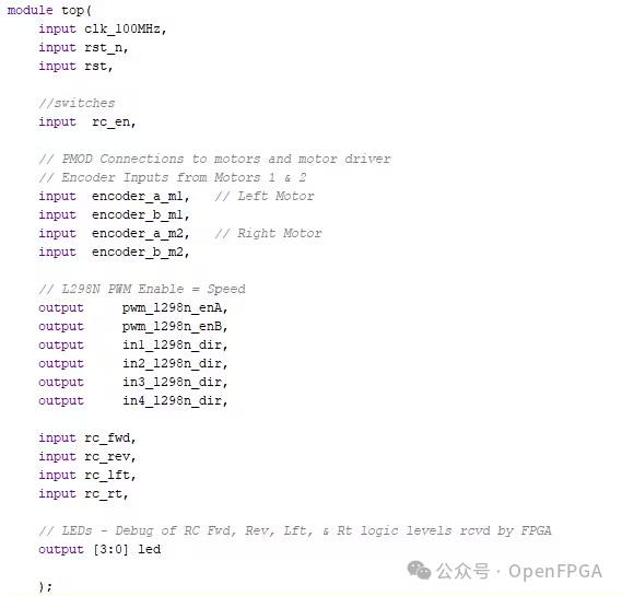
Next is the Verilog code for the input and output signal declarations for interfacing the FPGA with the external components (Figure 17). In this case, it is used for the L298N, two 12V DC encoder motors (Figure 1), and the RC receiver unit (not shown).
Encoder Counter Module
The code used for the encoder counter module is sourced from fpga4fun.com [9] (http://fpga4fun.com/). There, detailed explanations and waveform diagrams of the logic used can be found. Essentially, it determines the count and direction of spins using the system clock for oversampling, a few logic gates, and D flip-flops (adding a few extra flip-flops for crossing clock domains). Figure 18 shows the implementation of the code.
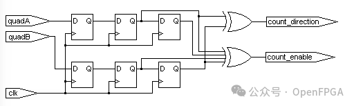
I also added logic that only creates positive counts. This is necessary for the PID we will discuss later.
RC Signal Selector Module
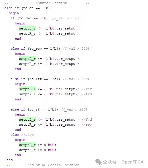
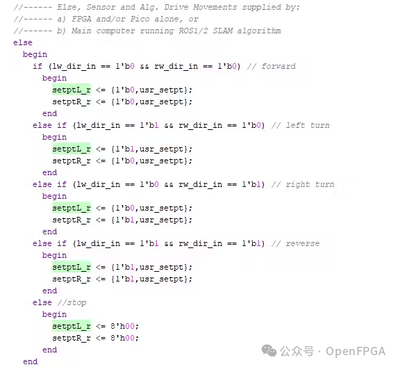
The name of this module is somewhat misleading. Initially, this module was only used to receive direction signals from the RC module and convert each signal into a two-bit value (Figure 19). One bit indicates whether the left wheel should move forward or backward, and the other bit indicates the same for the right wheel. Each bit is located at the most significant bit (MSB) of each setpoint (left and right wheels). Currently, the left and right motor setpoints coming from this module into the PID module are the same value (bits [6:0]). User setpoints can be changed in the top module by initializing curr_setpt1 and 2 to new values and then running Vivado for synthesis, implementation, and bitstream generation. This process takes about two minutes.
PWM Module
As mentioned above, the user setpoints (top-level named curr_setpt1 & 2) are stored in the lower 7 bits of an 8-bit register. Therefore, the setpoint value ranges from 0 to 127. This value represents the duty cycle of the PWM fed into the L298N. How does PWM convert the setpoint into duty cycle time width? This is achieved through a 7-bit counter in the PWM module. The PWM output is initially logic high (counter = 0). When the counter, counting at a clock frequency of 256 kHz, reaches the setpoint, the PWM output goes logic low until the counter reaches 127. The result is a 2kHz square wave PWM with a duty cycle of setpoint/127.
An 8.192 MHz clock was generated from the 100 MHz system clock using the Vivado clock wizard. Thus, one bit of the counter in the 256 kHz module only needs to be compared with logic “1”. The final PWM frequency is 2 kHz, close to the 1.5 kHz example [2], and works well.
PID
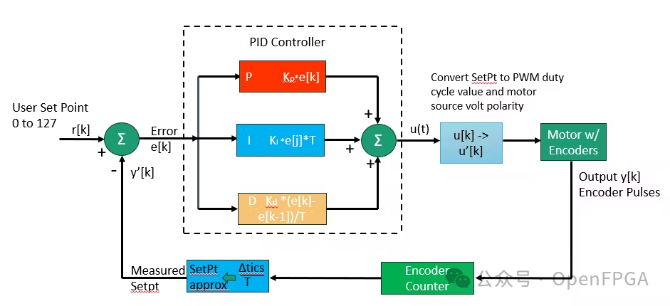
The design of the PID controller module was not as simple as I imagined. The issue lies in the conversion between the setpoint (0 – 127) and the incremental count read back during each setpoint sampling period T (e.g., 100 milliseconds). Figure 21 shows the block diagram of the PID feedback loop under discussion.
For me, the problem here was that I did not see (nor generate) the low error conversion from delta tics (counts) back to the setpoint.
Therefore, I decided to use the setpoint input r[k] as the reference value and add a modified value (error value) based on the difference between the previous counts and the current counts of the two motors, thus including discrete time analysis/comparison of the total count difference for each motor per period T (speed).
Based on experience with these small DC encoder motors, it is noted that one motor’s torque is often greater than the other motor’s at the same PWM duty cycle setting. Therefore, in the PID control algorithm, it can quickly determine which motor responds faster and use it as the master motor to match speed and travel distance. This way, the speed modification will only apply to the setpoint input r[k] of the slower motor. Otherwise, the motor speed will rise very quickly.
Let’s look at the proposed lead-follow equation and then examine the pseudocode for this discrete lead-follow motor feedback control loop.
e[k] = Feedback_1[k] – Feedback_2[k]; (1)
Where e[k] is the error calculated at the sampling period k, and Feedback_n[k] is the encoder counter value of motor n (i.e., n = 1 or 2) at the sampling period k.
Δx1[k] = Feedback_1[k] – PrevFeedback_1[k-1] (2)
Δx2[k] = Feedback_2[k] – PrevFeedback_2[k-1] (3)
Δx1x2[k] = Δx1[k] – Δx2[k] (4)
Where PrevFeedback_n[k-1] is the encoder count Feedback[k-1] of motor n saved at the sampling period k-1, and Δx1x2[k] is the speed difference between motors 1 and 2.
Similar to the PID control system shown in Figure 21, there are some weight values (constants Ki, Ke, and Kv) used to multiply formulas (1) and (4) and then add them together. Thus, the resulting formula is as follows (part of the code shown in Figure 22):
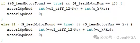
We will discuss the overall equation of the local discharge after the error equation is:
u[k] = setpoint[k] + motorNSpdMod (5)
Where N again represents the motor number 1 or 2.
You may notice that formula (5) lacks an integral element. I will explain how to add the integral to u[k] (formula 5), which is key to smoothing the oscillation of the error in the FPGA code part (repeatedly from positive to negative), but was not initially considered.
After writing the design code in Verilog using Vivado, I created a simulation model for the DC encoder motor and instantiated it on the test bench twice. The motor model samples the PWM wave input from the unit under test (UUT) and converts the calculated speed into corresponding frequency encoder A/B channel waveforms. The encoder waveform channels are input into the UUT. Additionally, I added a “resistance” value to reduce the speed of the motor relative to the other motor. This results in fewer encoder counts for the slower motor, thus resembling the actual motor and system response. Of course, this is a very simple model, as the resistance added to one motor is constant. It would be very beneficial to create at least a simple physical inertia response in the motor model. The model also assumes that the mobile robot operates on a constant flat horizontal surface.
Unfortunately, I found that the response of the robot after landing differed from the simulation results, which I had previously anticipated without a physical model.
The formulas used in the FPGA were tested and modified as needed (e.g., shortening T values, adjusting Ke and Kv values, etc.), initially validated using an Arduino Mega MCU and FPGAbot (without FPGA) in C/C++. This shortened the validation and modification cycle. The following code snippet comes from the Mega test (function PD_Alg(args)), representing the lead-follow algorithm (Figure 22).
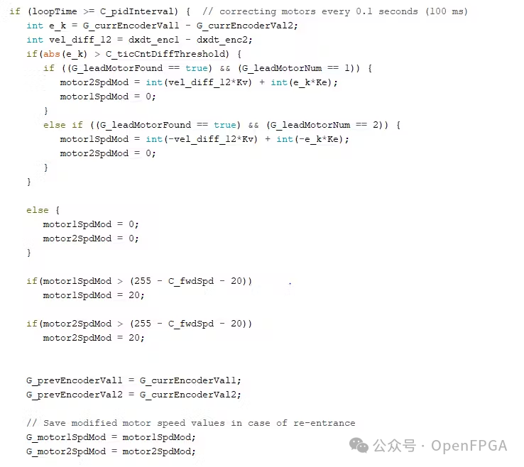
The lower part of the code, motorNSpdMod, checks against the maximum setpoint (255 – C_fwdSpd – 20) to prevent values from being too high. 255 is the maximum duty cycle value (0 to 255), C_fwdSpd is actually the setpoint for both motors (the same value), and 20 is just an arbitrary value that seems reasonable when viewing the data scrolling in Serial.print() on the Arduino IDE console, as shown in Figure 23.
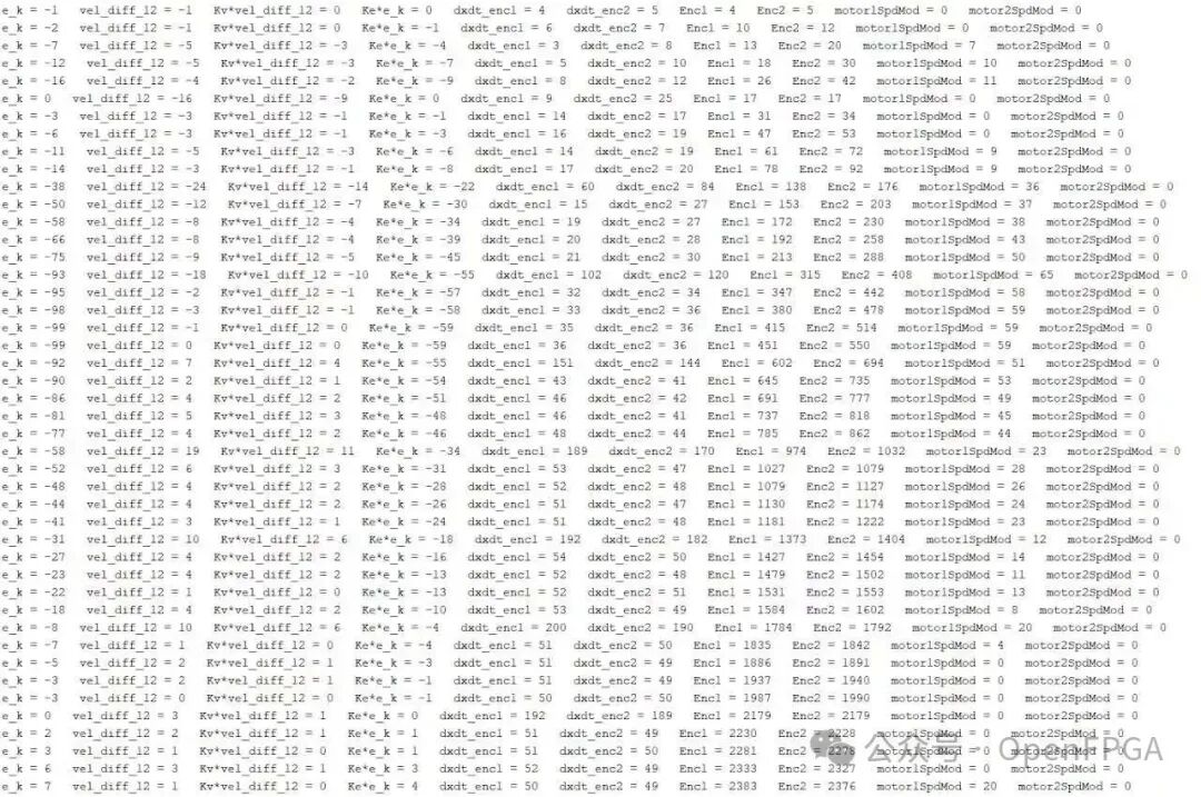
From the printed data, it is clear that better responses can be achieved by slightly adjusting Ke and Kv, or even adding an integral element to the mix.
Implementation of Lead-Follow PID Equation Variant in FPGA
Figures 23a and b show the simulation results before and after adding the integral to the lead-follow equation (5).
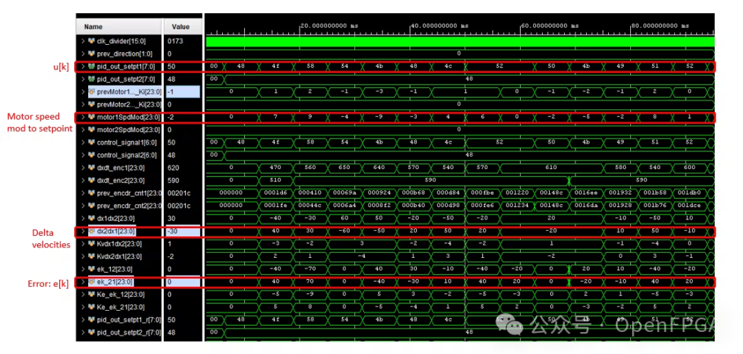
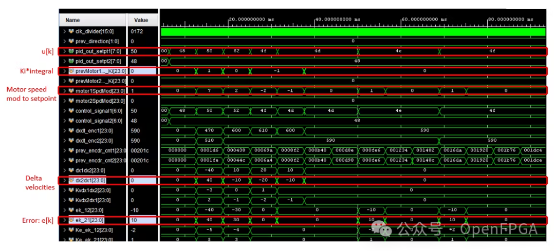
The following figures (Figures 25a and b) represent e[k] (error), dx1dx2 (motor speed change), and u[k] (motor modulation value). Figure 25b also adds the data for Ki*integral[k] (the sum of modulation values multiplied by a fraction), which is listed in formula (6).
u[k] = setpoint[k] + motorNSpdMod + Ki ΣmotorNSpdMod (6)
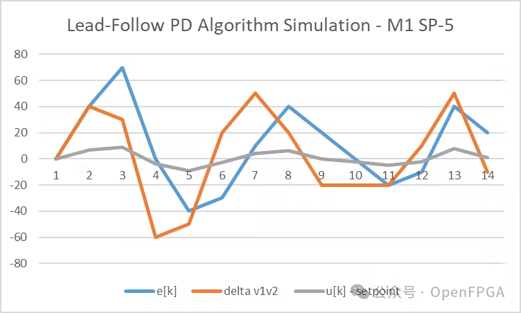
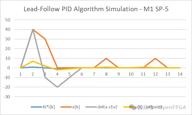
From these two figures, it is not difficult to see that the integral in this case quickly suppresses the oscillation of the error and speed increment. This allows for a very smooth adjustment of u[k], aligning closely with the original setpoint.
Lead-Follow FB Control Algorithm Verilog Code
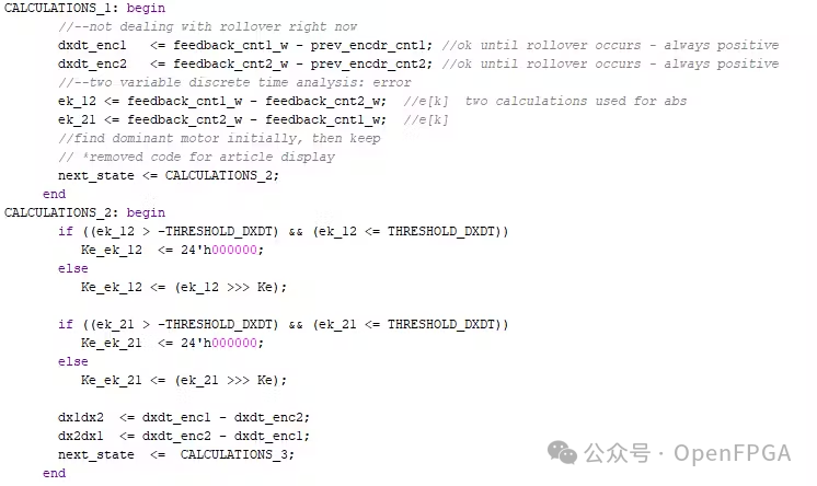
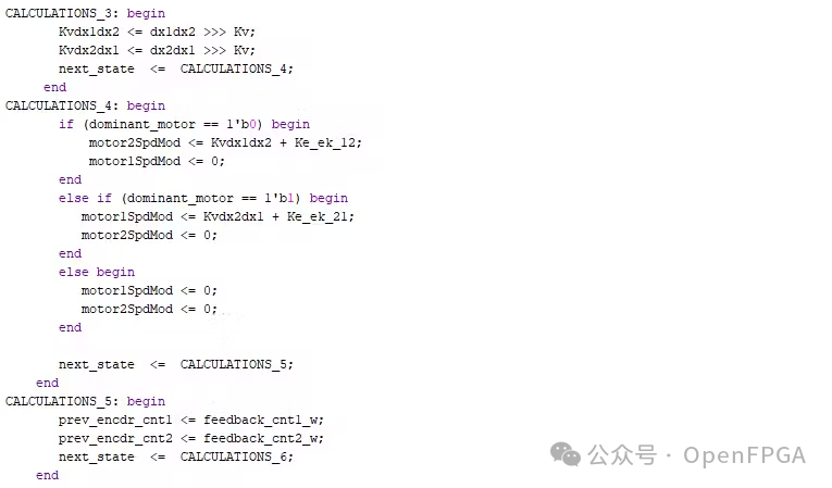
The C/C++ code shown in Figure 22 runs sequentially on the MCU. This is how they work. To replicate the sequential calculations in Verilog, a state machine is used to switch from one computation state to another every 10 ns (100 MHz system clock). The algorithm’s calculations are distributed across 7 states, with a computation time of 70 ns. There is no concern about shortening the computation time by a few nanoseconds at the expense of code readability. Compared to the sampling period T, the time saved is small by three orders of magnitude in duration. To make it more readable, breaking the calculations into several concise stages would create data dependencies, requiring additional clock cycles.
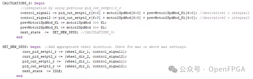
To avoid using floating-point representations for Ki, Ke, and Kv, thus saving a significant amount of FPGA logic resources, the error, speed increment, and integral are approximated by right-shifting (dividing by 2^n). However, caution is needed when using signed and unsigned variables (registers) in Verilog. I found that using logical shifts “>>” on negative numbers ultimately yields a large positive number. To avoid this, arithmetic right shifts represented as “>>>” should be used.
The code in Figures 26a, b, and c demonstrates the concepts covered so far in implementing the PID lead-follow feedback (FB) control algorithm in Verilog, and it has been simulated in Vivado (Figures 24a and b).
Others
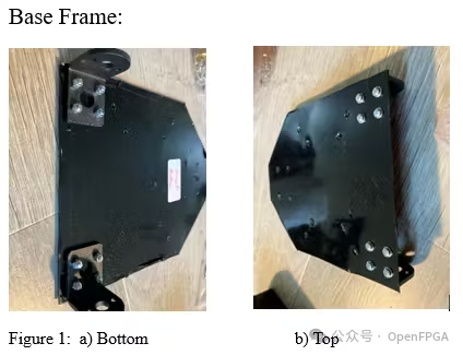
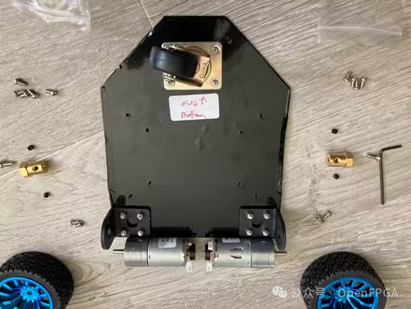
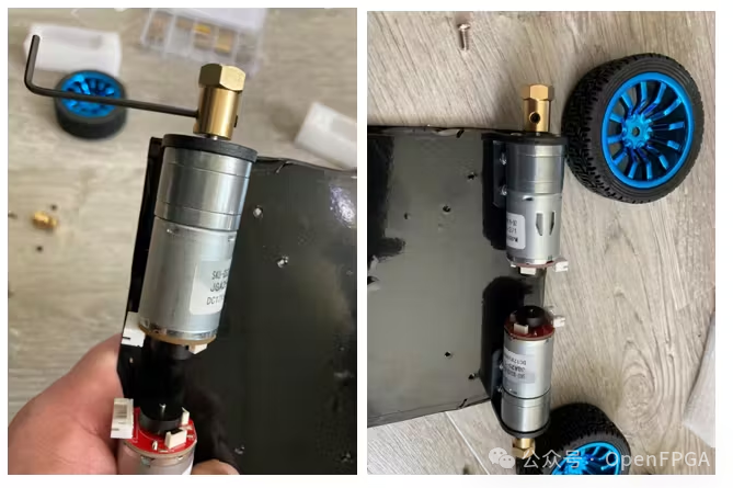
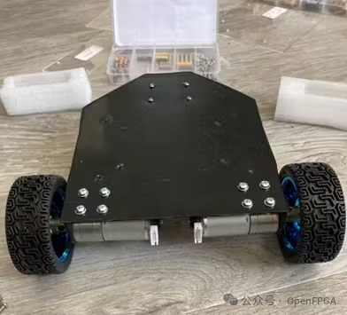
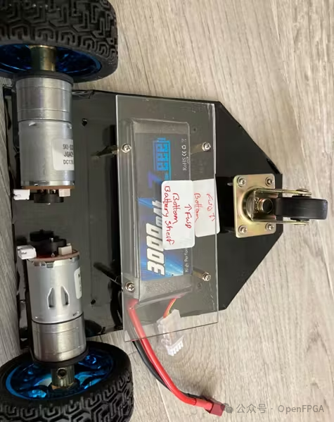
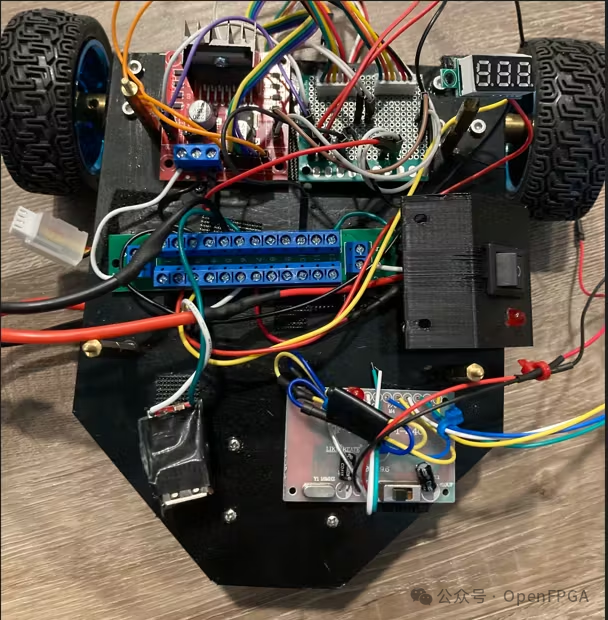
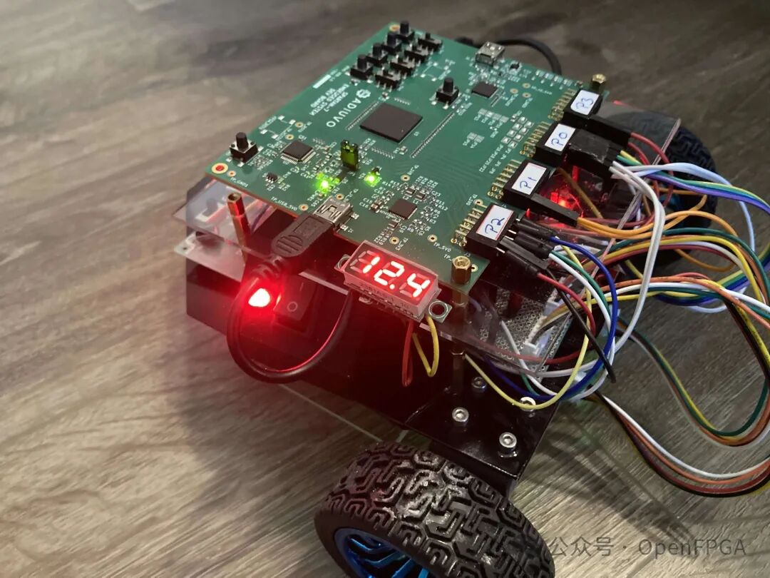
Some additional details can be seen in a set of images~
Project Address
The complete project can be found on GitHub.
https://github.com/ZenoRobotics/FPGAbot-HacksterIO
References
[1] STMicroelectronics L298 IC Datasheet.
https://www.st.com/en/motor-drivers/l298.html
[2] L298N Motor Driver and PWM Details PDF published by BYU (Brigham Young University).
https://brightspotcdn.byu.edu/cd/87/bbf866d84c06a0c52fa995396f30/l298n-motor-driver-quick-start-v6.pdf
[3] STMicroelectronics L297 Stepper Motor Controller Datasheet.
https://www.st.com/content/ccc/resource/technical/document/datasheet/f9/35/6e/3f/48/18/48/51/CD00000063.pdf/files/CD00000063.pdf/_jcr_content/translations/en.CD00000063.pdf
[4] “What is an H-Bridge”.
https://www.build-electronic-circuits.com/h-bridge/
[5] “NPN Transistor”.
https ://www.electronics-tutorials.ws/transistor/tran_2.html
[6] “Basics of PWM”.
https ://docs.arduino.cc/learn/microcontrollers/analog-output/
[7] Rechtenwald, G. “Basic DC Motor Circuits”.
https ://cdn.sparkfun.com/assets/resources/4/4/DC_motor_circuits_slides.pdf
[8] “Understanding Resolution in Optical and Magnetic Encoders”.
https ://www.electronicdesign.com/technologies/components/article/21798142/understanding-resolution-in-optical-and-magnetic-encoders
[9] “FPGA Project: Quadrature Decoder”.
https ://www.fpga4fun.com/QuadratureDecoder.html