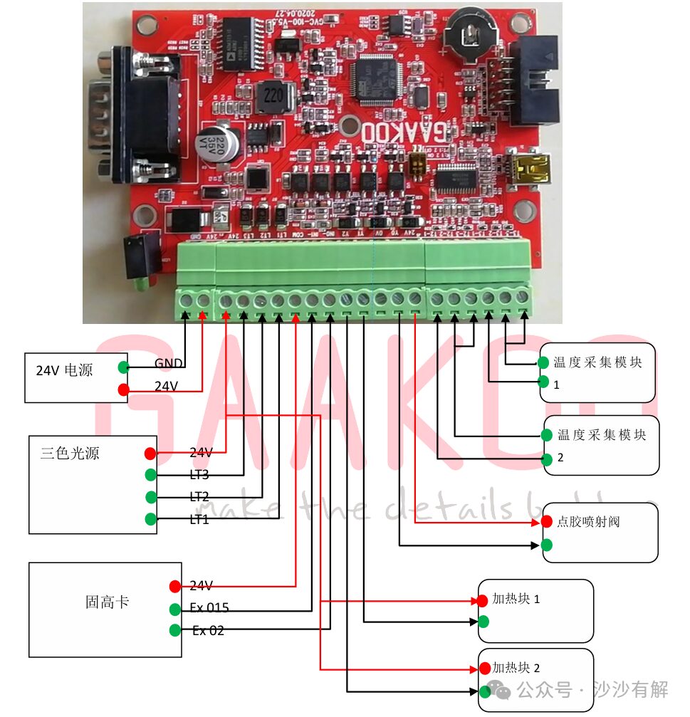
1: Control Card Power Supply
24V Power Supply—->24V
Power Ground—->GND
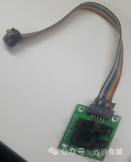
2: Three-Color Light Source
Light Source 24V(Brown Wire)<——– Control Card 24V
Light Source Red, Green, Blue<——– Control Card LT1,LT2,LT3
3: Glue Dispensing Trigger :
Guhigh Card 24V ———–> Control CardCom
Guhigh Card Ex015 ———> Control Card In1- (Reserved)
Guhigh CardEx 02 ——-> Control Card In0- (Glue Dispensing Trigger)
4: Glue Pneumatic Injection Valve
24V and Y0——> Glue Pneumatic Injection Valve
5: Temperature Acquisition Module1; Temperature Acquisition Module2( PT100/Thermocouple Wire Interface)
2 Channels Three-Wire PT100 or K Type Thermocouple as Temperature Sensor Input(2 Channels Input Must Be the Same Type, i.e., Both PT100 or K Thermocouples)
K Type Thermocouple Wiring:
1)T1-1(K Type Thermocouple Positive Terminal)
2)T1-2(K Type Thermocouple Negative Terminal)
3)T2-1(K Type Thermocouple Positive Terminal)
4)T2-3(K Type Thermocouple Negative Terminal)
5)T1-3、T2-3 Empty Connection
5: Heating Block
Heating Block1: 24 V(Shared with Light Source) + Y1
Heating Block2: 24 V(Shared with Light Source) + Y2
7: Control Card Communication Interface (Simply plug in the standardRS232 Serial Cable)
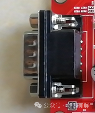
SerialRS232 Signal (Use a Male-to-Male Direct Connection with the Industrial Control Computer))
1)GND(Power Ground)
2)RX(Controller Data Receiving End)
3)TX(Controller Data Sending End)
4)GND(Power Ground)
8: Pressure Control Expansion Interface: (Simply plug in the connection cable of the expansion card)
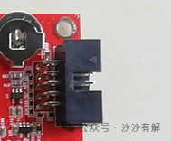 Expansion Interface
 Pressure Expansion Card
Note:
1)The maximum allowable pressure at the air pipe is 700KPA.
2)The maximum pressure difference between the input trigger signals, IN+ and IN- is not more than 27V, minimum 21V.
Below 21V may cause the system to not detect the trigger, while exceeding 27V may burn the circuit.
3)The output signal is an open-drain output. When controlling the solenoid valve, one wire of the solenoid valve connects to 24V, and the other wire connects to VALVE. When controlling the light source, the positive terminal of the light source connects to 24V, and the negative terminal connects to LED.
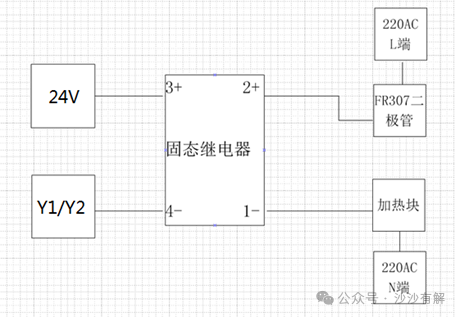
4)When controlling the heating block, it must go through the solid-state relay. The positive terminal of the solid-state relay input connects to 24V, and the negative terminal connects to Y1/Y2 wire. The AC220V ‘L’ end connects to the positive terminal of the FR307 diode, and the negative terminal of the diode connects to the positive terminal of the solid-state relay output, while the relay’s negative terminal connects to one end of the heating block, and the other end of the heating block connects to the 220VAC ‘N’ end.
The wiring method for the heating module is as follows:
JVC Communication Protocol V1.04
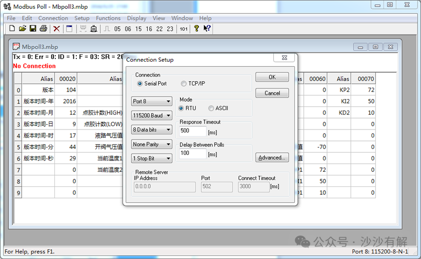
The controller has serial communication capabilities and uses the standard MODBUS-RTU protocol for communication.
The communication baud rate is 115200,8 data bits, 1 stop bit, no parity bit, and the slave ID is 1.
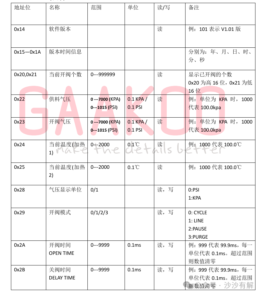
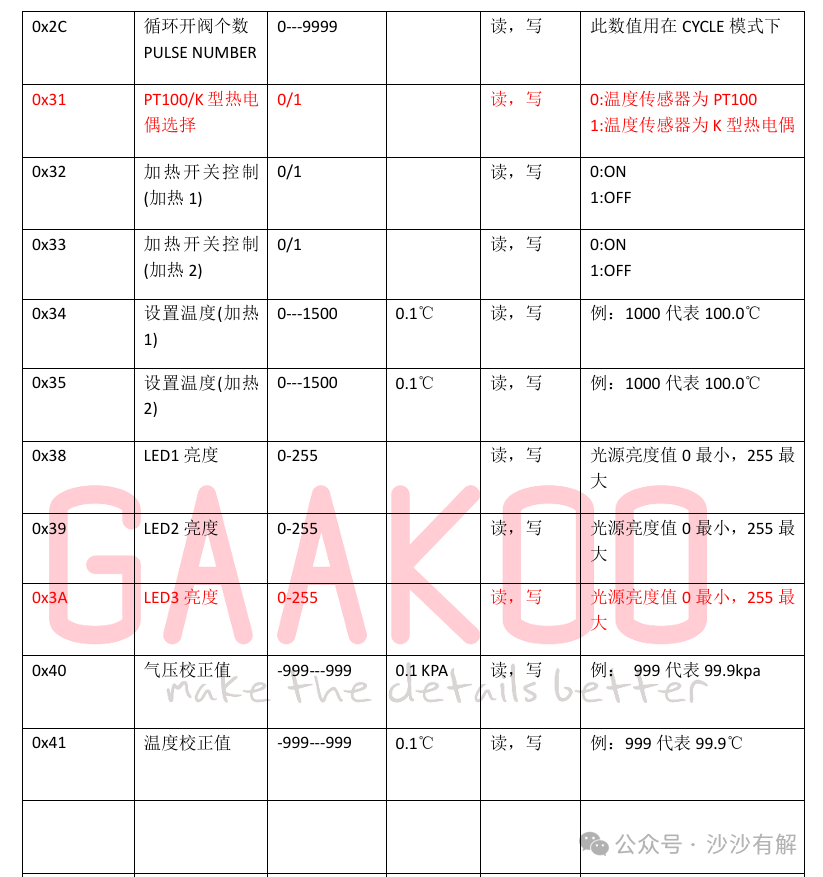
1: Communication Protocol
2: Example
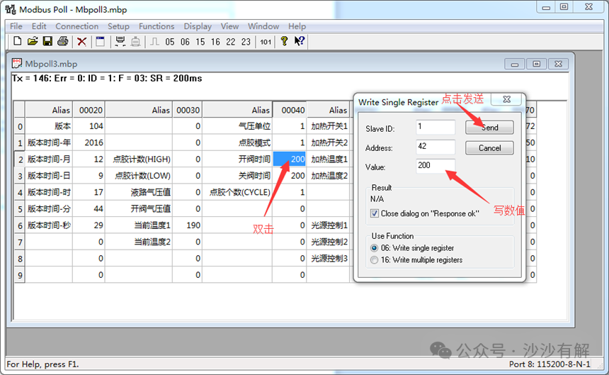
Connect the main control board’s serial port to the computer’s serial port, and install ModBusPoll.4.3.4 on the computer side.
Open the software Modbus Poll, go to the menu File/Open, and open the already set file (*.mpb), as shown in the figure, 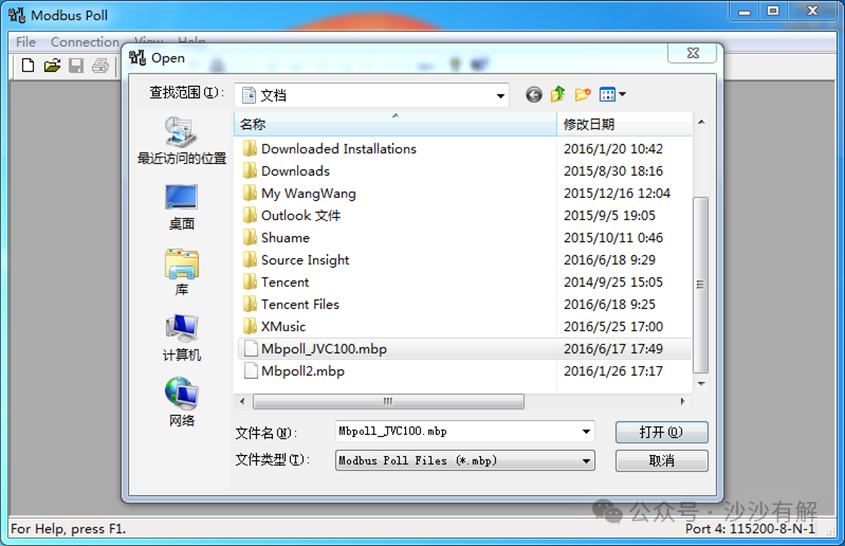
Go to the menu Connection/connect… to set the serial port, baud rate, etc., as shown in the figure
After setting the serial port, click connect, as shown in the figure
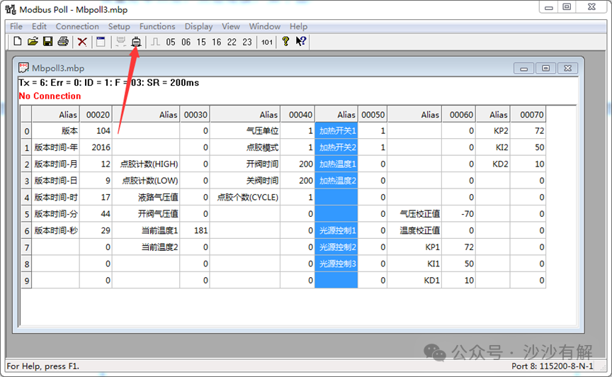
After connecting, the software will automatically read the register values; for write operation example: double-click the value, fill in the value, click Send, and after successful sending, the window will close automatically, as shown in the figure.