“ The choice of firmware programming methods is crucial throughout the entire lifecycle of embedded products. From development and debugging to mass production and on-site updates, various programming methods have their respective applicable scenarios. This article outlines the circuit design and applications of mainstream methods such as JTAG and SWD, comparing their versatility, advantages, and disadvantages, providing a reference for selecting programming solutions at different stages.“
01
—
Common firmware programming methods in the embedded field
1. JTAG (Joint Test Action Group) Circuit Design:
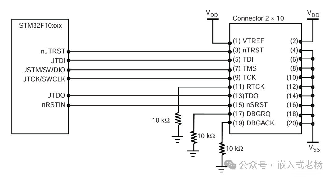
Core Pins: TCK (Test Clock), TMS (Mode Select), TDI (Data Input), TDO (Data Output), some chips require TRST (Reset).
Signal Integrity:
-
TCK and TMS should be routed as differential pairs, with a spacing of ≥100mil, and a series 33Ω resistor to suppress EMI.
-
TDI/TDO should be push-pull output, no pull-up required; TMS requires a 10kΩ pull-up resistor.
-
Level Shifting: Multi-voltage systems require level shifters like SN74LVC2T45.
Typical Applications:
Debug interface design for STM32, FPGA, such as the connection between the Tiny Jlink debugger’s JTAG interface and STM32F103C8T6.
2. SWD (Serial Wire Debug) Circuit Design:

Core Pins: SWDIO (Bidirectional Data), SWCLK (Clock), requires a 4.7kΩ pull-up resistor to VDD.
Signal Integrity:
-
Trace length ≤5cm, differential pair layout, spacing ≥100mil, series 30-100Ω resistor.
-
Place a 100nF decoupling capacitor close to the chip end.
-
Timing Optimization: SWCLK frequency can reach 100MHz, must match the chip’s main frequency.
Typical Applications:
Connection of PA13 (SWDIO) and PA14 (SWCLK) of STM32F103 to the debugger.
3. UART ISP One-Key Download Circuit Circuit Design:
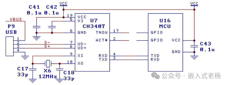
The above circuit is a reference circuit for the MCU microcontroller connected to the CH340 chip via TTL serial port for USB communication under dual power supply mode. The CH340 is powered by the USB bus VBUS, while the MCU uses another power supply VDD, which supports 5V, 3.3V, and even 2.5V, 1.8V. The RXD pin of the MCU should enable the internal pull-up resistor; if not, it is recommended to add an external pull-up resistor of 2KΩ to 22KΩ to the RXD pin connected to the MCU’s power supply VDD.
Typical Applications:
Automatic download circuit for STM32 development boards.
4. SPI ISP Circuit Circuit Design:
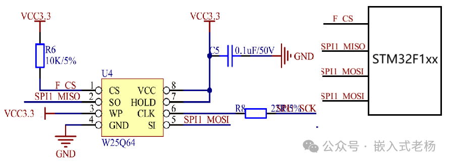
Pins: MOSI, MISO, CLK, CS.
Typical Applications:
STM32F1xx connected to W25Q64 Flash via SPI for firmware programming.
5. USB to Serial:
Using FT232RL or CH340C chips, D+ and D- connect to USB differential lines.
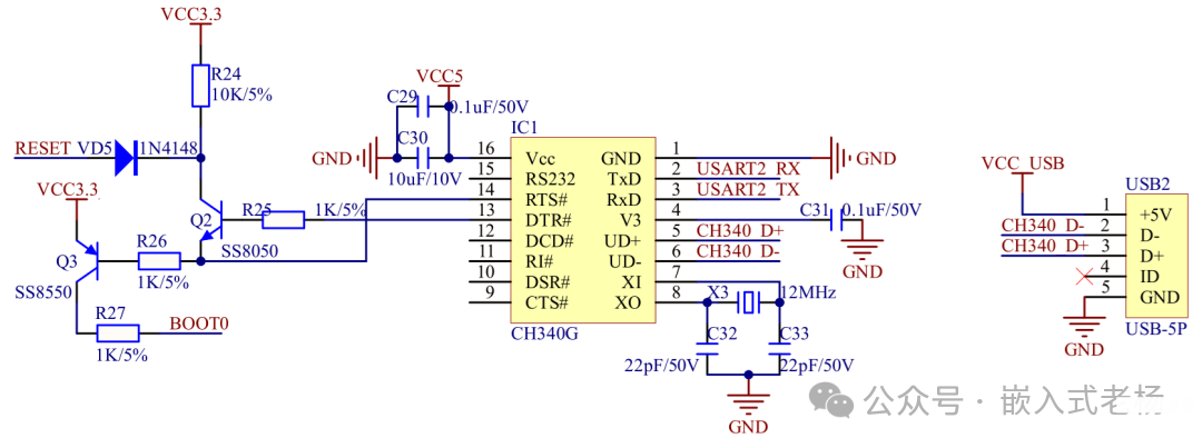
The principle of the USB to serial circuit for programming firmware is to use the CH340G chip to convert USB signals into serial communication signals. By controlling the RESET and BOOT0 pins of the microcontroller (MCU), the MCU enters bootloader mode, allowing the computer to program firmware to the MCU via the USB interface; where Q2 and Q3 transistors control the RESET and BOOT0 pins of the MCU to achieve MCU reset and boot mode selection, completing the firmware programming.
Typical Applications:
USB to serial circuit of the ESP-LINK development board, supporting one-key download for ESP8266.
6. SD Card Programming Circuit Design:
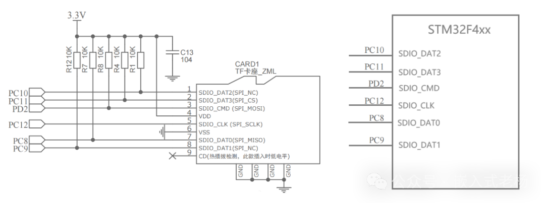
In the above circuit, the STM32 connects to the TF card socket through pins PC10, PC11, PD2, PC12, PC8, PC9, using the SDIO interface to communicate with the SD card. Among them, SDIO_DAT0 – SDIO_DAT3 are used for data transmission, SDIO_CMD is for command sending, and SDIO_CLK provides the clock signal. When programming firmware, the STM32 sends commands through the SDIO interface to read the firmware data stored on the SD card, and then writes the data into its own storage area to complete the firmware programming; at the same time, the CD pin can detect whether the SD card is inserted, and the 3.3V power supply provides appropriate voltage levels for related pins through multiple 10K resistors and other components.
Typical Applications:
Embedded devices update firmware via SD card, supporting upgrades in environments without network.
7. Bluetooth Wireless Programming Circuit Design:
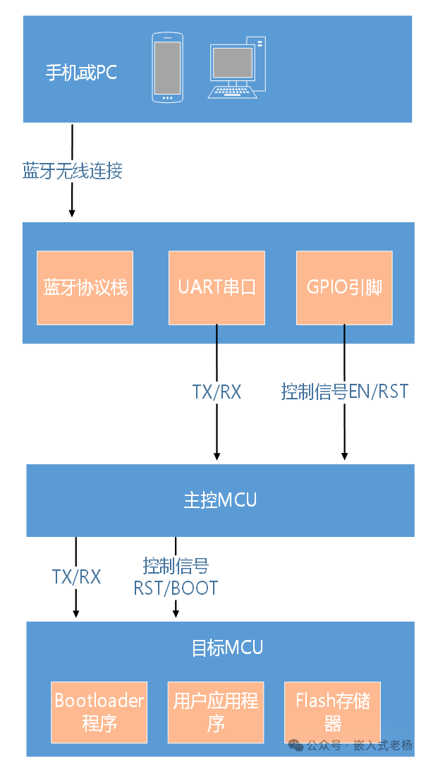
By constructing a wireless bridge through a Bluetooth module, users initiate programming tasks from a mobile phone or PC. Firmware data is transmitted via the Bluetooth protocol stack and forwarded to the main MCU through the module’s UART serial port; at the same time, the GPIO pins of the Bluetooth module output control signals (such as EN, RST), directing the main MCU to control the target MCU to enter bootloader mode and complete the reset timing. Ultimately, the main MCU transmits the received firmware data stream to the target MCU’s bootloader program, which executes the erase and write operations, thus achieving wireless updates of the application program.
Typical Applications:
Arduino Pro Mini achieves wireless programming through HC-05 without manual reset.
8. WIFI Wireless Programming Circuit Design:
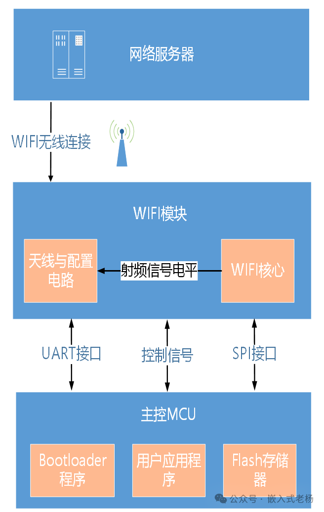
The WiFi module on the device side receives new firmware data from the network server via the antenna, and its internal core transmits the data to the main MCU via UART or SPI interface; the main MCU is taken over by the bootloader program in upgrade mode, writing the received firmware data into a specific partition of the Flash memory. After writing and verification, it switches the boot partition to run the updated user application, thus achieving wireless updates of the entire firmware.
Typical Applications:
Smart home center devices such as smart speakers or gateways update system software wirelessly; sensors and controllers in industrial environments use WIFI wireless programming technology for remote firmware upgrades.
02
—
Comparison of Various Programming Methods
In addition to the above 8 methods, there are several other important firmware programming methods in the embedded field:
1. CAN Bus Programming (based on protocols like UDS)
Instead of directly transmitting raw firmware data packets, it follows higher-level protocols such as UDS (Unified Diagnostic Services, ISO 14229). Diagnostic tools send service requests like RequestDownload, and the target ECU enters extended session mode to receive encrypted and verified firmware data blocks via the TransferData service.
2. Ethernet Programming (TFTP/HTTP)
Used for firmware upgrades in network devices (routers, switches), industrial gateways, and high-end HMIs.
TFTP: The device’s bootloader integrates a simple TFTP client, which downloads firmware from a preset TFTP server upon power-up.
HTTP: The device runs a lightweight web server, allowing users to upload firmware files for upgrades via a browser.
3. USB DFU (Device Firmware Upgrade)
The chip has a built-in DFU bootloader, enumerating the device as a special DFU class device via USB. The host uses dedicated tools (like dfu-util) to write firmware files directly into the device’s program memory via USB protocol.
4. Parallel Programming
Directly accesses the chip’s memory space through a complete 8/16-bit data bus, address bus, and control signal lines (OE, WE, CE) for high-speed, parallel data writing.
The table below compares all methods and uses stars to indicate versatility levels (five stars being the highest).
|
Programming Method |
Versatility Rating |
Core Advantages |
Core Disadvantages / Limitations |
Dominant Application Scenarios |
|
SWD |
⭐⭐⭐⭐⭐ |
ARM Cortex-M de facto standard, fewer pins, good speed, supports debugging |
Essentially exclusive to the ARM ecosystem |
ARM MCU development, debugging, mass production |
|
UART ISP |
⭐⭐⭐⭐ |
Almost all MCUs support it, extremely low cost, simple circuit |
Slow speed, usually requires manual reset intervention |
On-site maintenance of products, small batch updates |
|
USB DFU |
⭐⭐⭐⭐ |
Excellent user experience, fast speed, plug and play |
Requires built-in USB functionality in the chip |
Consumer products with USB, development boards |
|
WIFI OTA |
⭐⭐⭐⭐ |
Mainstream in IoT, wireless, remote, good user experience |
Complex design (security/network/power consumption) |
IoT devices, smart homes |
|
JTAG |
⭐⭐⭐ |
Powerful functionality, supports boundary scan, standardized |
Many pins, complex wiring, high cost |
FPGA/complex ASIC, high-end debugging |
|
SD Card |
⭐⭐⭐ |
No need for PC and cables, suitable for large firmware |
Increases BOM cost, requires file system |
Multimedia, industrial devices offline upgrades |
|
Bluetooth OTA |
⭐⭐⭐ |
Low power, direct connection to mobile, wireless |
Slow speed, short distance |
Wearable devices, personal medical devices |
|
CAN Bus |
⭐⭐ |
High reliability, suitable for harsh environments |
Very niche (automotive/industrial), high cost |
Automotive ECU flashing, industrial networks |
|
Ethernet |
⭐⭐ |
High speed, suitable for local area network environments |
High hardware cost, complex design |
Network devices, industrial gateways |
|
Parallel Programming |
⭐ |
Extremely fast speed |
Limited to production programming fixtures, complex circuitry |
Chip programming before leaving the factory |
03
—
Conclusion
1. Development and Debugging Stage:
Preferred SWD: for ARM MCU, achieving the best balance in performance, functionality, and convenience.
Secondary choice JTAG: used when debugging FPGA, multi-core processors, or performing boundary scans.
2. Production and Mass Production Stage:
High-speed programmers: use dedicated programmers based on SWD/JTAG interfaces, interfacing with PCBs through fixtures.
ICT/Bed-of-Nails: online testers can simultaneously perform testing and programming.
UART ISP: used in cost-sensitive and low-volume scenarios.
3. On-site Update Stage:
Preferred WIFI OTA: for connected IoT devices, the best user experience.
Secondary choice USB DFU: for products with USB, providing a PC-like upgrade experience.
Backup SD Card/UART: for scenarios without network or requiring forced upgrades.
Summary:
From the entire lifecycle of embedded products, SWD (development), UART (maintenance), and WIFI/Bluetooth OTA (updates) form the most versatile “iron triangle”, covering the vast majority of application scenarios. Other methods are important supplements under specific hardware or specific fields. The choice of method ultimately depends on your chip selection, product form, and cost control requirements.
Previous Articles::
Introduction to FreeRTOS Tasks
Types of Diodes, Working Principles, and Applications
MCU Low Power Modes
Wi-Fi 7 is here! 5 times faster than Wi-Fi 6, your network is about to take off!
Recommended book for beginners in electronic design (including electronic version)
Microcontroller AD Acquisition Filtering Algorithm