“Stamping motion control, uncovering the secrets of servo presses and robotic arms”
Lib_AxisMonitor function block is typically used to monitor the operational status of rotating or linear axes. After receiving a running signal, it detects the minimum displacement change of the axis within a specified period. Based on this, it can determine faults such as mechanical jams, abnormal positions, or mechanical damage, ensuring the safe and reliable operation of the equipment.
Program Call
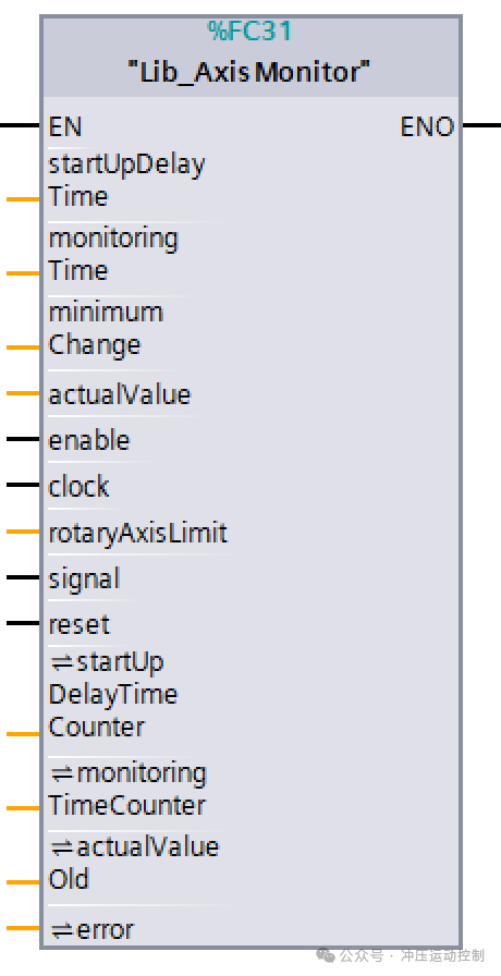
Interface Definition
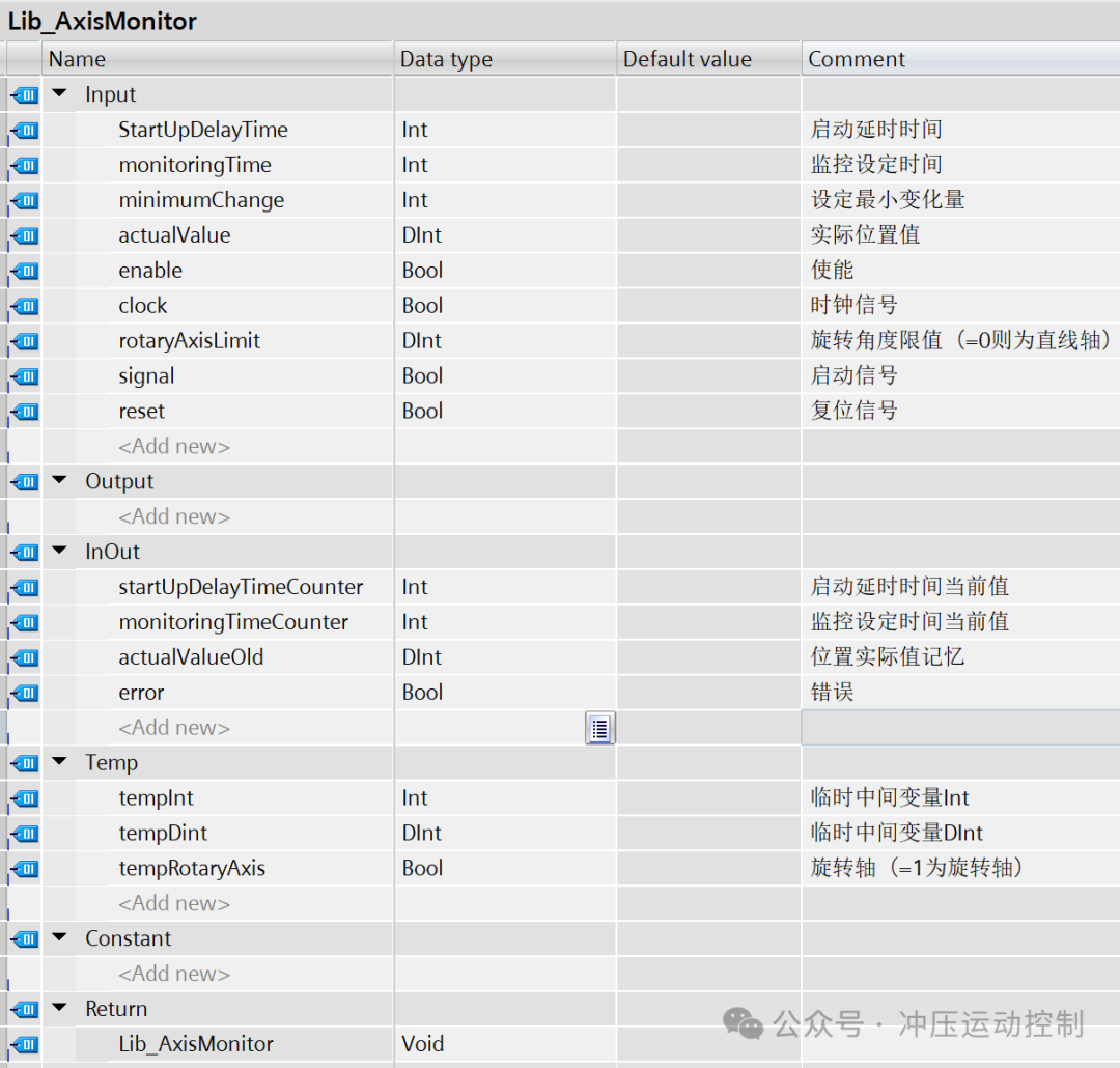
Startup Delay Time (startUpDelayTime): Allows the device to briefly ignore position changes during the initial startup phase (e.g., motor acceleration) and enter the monitoring phase only after the speed stabilizes, to avoid false alarms.
Monitoring Time (<span><span>monitoringTime</span></span>): Defines the time window during which position stagnation is allowed. If the minimum change is not reached within this window, an error is triggered.
Automatic Switching Between Rotating and Linear Axes: Based on the <span><span>rotaryAxisLimit</span></span> parameter (=0 for linear axis, >0 for rotating axis), it automatically selects the difference calculation algorithm.
Threshold Judgment: If the change is below the set threshold (<span><span>minimumChange</span></span>), it is determined as a jam and triggers an error error.
Actual Value (actualValue): Filtering can be applied to a certain extent, such as moving average filtering, to prevent signal jitter from affecting judgment.
Program Code
// Rotating axis mode judgment#tempRotaryAxis := (#rotaryAxisLimit > 0); // System enable and error detectionIF NOT #enable OR #error THEN // Execute reset process IF #reset THEN #error := FALSE; END_IF; #monitoringTimeCounter := #monitoringTime; #startUpDelayTimeCounter := #StartUpDelayTime; RETURN;END_IF; // Signal validity checkIF NOT #signal THEN // Save current value and reset counter #actualValueOld := #actualValue; #monitoringTimeCounter := #monitoringTime; #startUpDelayTimeCounter := #StartUpDelayTime; RETURN;END_IF; // Clock pulse detectionIF NOT #clock THEN RETURN;END_IF; // Startup delay phase processingIF #startUpDelayTimeCounter > 0 THEN #startUpDelayTimeCounter := #startUpDelayTimeCounter - 1; RETURN;END_IF; // Monitoring phase processingIF #monitoringTimeCounter > 0 THEN #monitoringTimeCounter := #monitoringTimeCounter - 1; RETURN;END_IF; // Position change calculationIF #tempRotaryAxis THEN // Rotating axis mode calculation IF #actualValue > #actualValueOld THEN #tempDint := #actualValue - #actualValueOld; ELSE #tempDint := (#rotaryAxisLimit - #actualValueOld) + #actualValue; END_IF;ELSE // Linear axis mode calculation #tempDint := ABS(#actualValue - #actualValueOld);END_IF; // Threshold judgment and error handlingIF #tempDint >= #minimumChange THEN // Position change is valid, update historical value #actualValueOld := #actualValue;ELSE // Trigger error state #error := TRUE;END_IF; // Counter reset#monitoringTimeCounter := #monitoringTime;#startUpDelayTimeCounter := #StartUpDelayTime;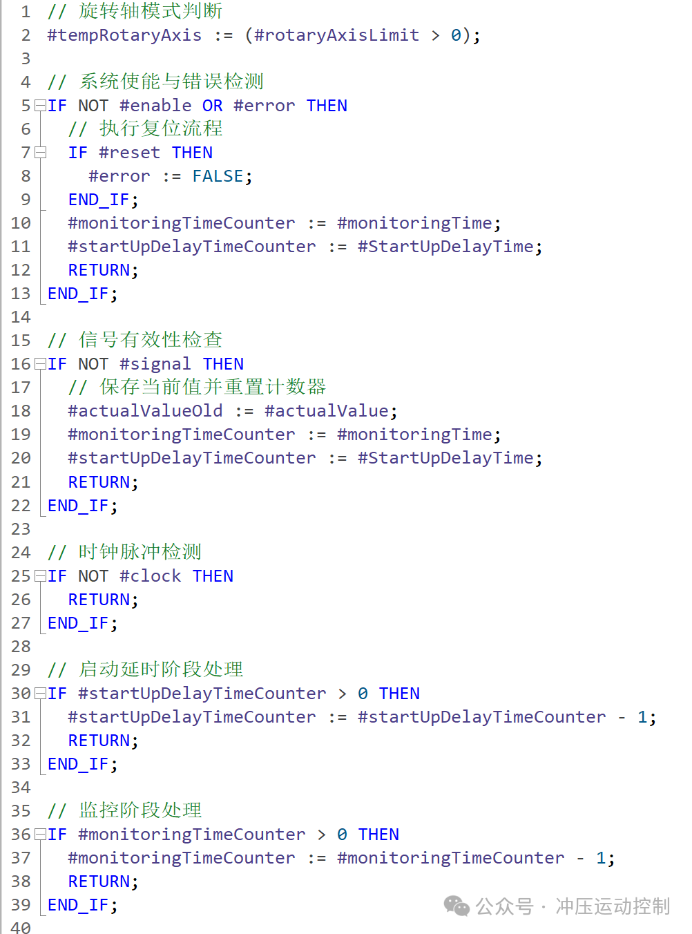
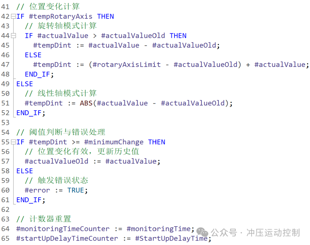 Real-time Difference Calculation: By comparing the current value (
<span><span>actualValue</span></span>) with the historical value (<span><span>actualValueOld</span></span>), the position change within the specified period is calculated.
Linear Axis: Directly calculate the absolute difference (<span><span>ABS(actualValue - actualValueOld)</span></span>).
Rotating Axis: Ensure correct difference logic for rotating axis displacement crossing the zero point.
Threshold Judgment: If the change is below the set threshold (<span><span>minimumChange</span></span>), it is determined as a jam and triggers an error.
END
Original History:
Example 83 of PLC User Standard Blocks – General Counter
Example 86 of PLC User Standard Blocks – Operation Mode Selection 2
Example 95 of PLC User Standard Blocks – Running Condition Encapsulation with Self-Diagnosis
Example 95 of PLC User Standard Blocks – Running Condition Encapsulation with Self-Diagnosis