Today, numerous applications rely on Digital-to-Analog Converters (DACs) and Analog-to-Digital Converters (ADCs). They are crucial in signal processing as they bridge the gap between digital systems and analog systems. By enabling digital circuits to interact with analog components, ADCs and DACs play a key role in fields such as audio processing, telecommunications, and data acquisition systems.
Moreover, in modern sensing technology, the application of magnetic sensors is becoming increasingly widespread, such as Hall effect sensors, Tunnel Magnetoresistance (TMR) sensors, and Giant Magnetoresistance (GMR) sensors. These magnetic sensors need to convert the detected magnetic signals into electrical signals, which is where ADCs and DACs play a critical role. For example, in automotive electronics, industrial automation, and medical devices, magnetic sensors are used for tasks such as angle detection, motor control, and non-contact measurements, relying on high-precision ADCs for signal acquisition and processing, while using DACs for high-precision feedback control. Therefore, the combination of ADCs, DACs, and magnetic sensors further expands the boundaries of intelligent sensing systems, providing more accurate and stable solutions for modern technological applications.
 The Role of DACs and ADCs
Analog-to-Digital Converters (ADCs) are one of the core components of modern Data Acquisition Systems (DAQ or DAS systems). Their role is to convert conditioned analog signals into digital data streams, allowing the system to process, display, store, and analyze this data. Due to the high precision required during the conversion process, even minor errors can significantly impact subsequent data analysis and processing.
On the other hand, Digital-to-Analog Converters (DACs) play an indispensable role in applications such as digital audio storage and streaming. They convert digital signals into analog signals, ensuring high-fidelity reproduction of audio and are widely used in various analog output devices to ensure accurate transmission of sound quality and other signals.
To ensure optimal performance, both ADCs and DACs require rigorous testing, focusing on parameters such as maximum sampling rate, bit resolution, Total Harmonic Distortion (THD), noise, Signal-to-Noise Ratio (SNR), Integral Non-Linearity (INL), Differential Non-Linearity (DNL), Effective Number of Bits (ENOB), and jitter, to ensure their efficient and stable performance in practical applications.
 Key Testing Methods for ADCsTesting ADC and DAC devices involves various techniques, and customized testing methods are often required for the unique functionalities of each converter. Depending on the target application, the focus of testing may vary. For example, testing requirements differ across video processing, imaging, telecommunications, control systems, and audio processing. The following table summarizes the most common testing methods in different applications:
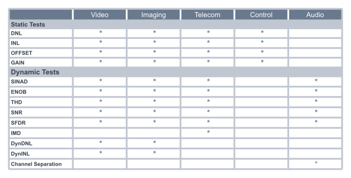
 Static Testing of ADCs
Integral Non-Linearity (INL) and Differential Non-Linearity (DNL)
ADC testing typically involves measuring key performance indicators, which usually include:
-
Offset Error
-
Gain Error
-
Differential Non-Linearity
-
Integral Non-Linearity
-
Missing Codes
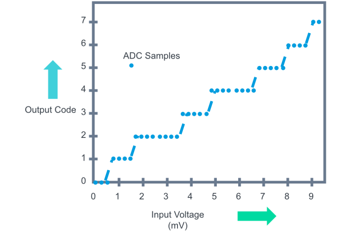
When testing the Differential Non-Linearity (DNL) and Integral Non-Linearity (INL) of an ADC, a signal is applied to the input, and the distribution of the output codes is analyzed. This differs from DAC testing, where a digital code is applied, and the analog output is measured using a precision voltmeter, while ADC testing requires determining the “decision level,” which corresponds to the input voltage at the code boundary.
Histogram Testing with Linear Ramp
This method applies a linear ramp signal and counts the occurrences (hits) of each output code. Ideally, the frequency of occurrence for each code should be equal. If a code appears more frequently than others, it indicates a wider step size, resulting in a positive DNL; if it appears less frequently, it indicates a narrower step size, resulting in a negative DNL. INL is derived from the cumulative sum of DNL.
Due to its ability to accurately assess the static characteristics of an ADC, the linear ramp histogram test (also known as code density testing) has become the most commonly used method for testing static parameters of ADCs.
Sine Wave Input Histogram Testing
The histogram method uses a sine wave signal as the input to the ADC. Compared to other signal forms (such as linear ramps), generating a pure sine wave is usually simpler.However, the voltage distribution of a sine wave is uneven, with more voltage steps concentrated in the lower and upper voltage ranges.
In this method, the ADC’s output is analyzed to evaluate the converter’s performance at different voltages. For DACs, high-precision digital channels combined with low-noise sine wave generators can assess performance within these voltage ranges, ensuring minimal distortion and noise.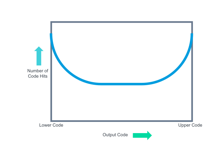
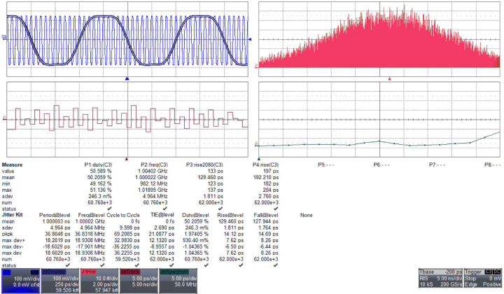
 Dynamic Testing of ADCsNoise Sources in ADC Testing
Accurate ADC testing must consider various noise sources, as noise can significantly degrade the performance of data converters. The three main noise sources include:
-
Jitter on Digital Signals: Jitter introduces errors at the moment of acquisition, leading to inaccurate signal capture. Reducing jitter can improve the Signal-to-Noise Ratio (SNR).
-
Waveform Generator Noise: The quality of the signal used for testing directly affects the test results. The SNR of the testing equipment must be higher than that of the Device Under Test (DUT) to ensure reliable results.
- Noise in Voltage Reference and Power Supply: Noise in the ADC’s voltage reference (Vref) or power supply translates into output noise as well as offset and gain errors. For more accurate testing, it is recommended to use an external voltage reference, and power supply noise must be precisely controlled through parameters such as Power Supply Rejection Ratio (PSRR).
 DAC Testing Compared to ADC testing, DAC testing typically requires less complexity. This process involves applying a series of digital codes to the DAC and measuring the corresponding analog output using a high-precision Digital Voltmeter (DVM). This allows for direct measurement of DNL (Differential Non-Linearity) and INL (Integral Non-Linearity). Although DAC testing is less complex, it still requires high-precision digitizers to ensure accurate results.
In cases where the digitizer’s accuracy is insufficient, additional testing strategies can be employed to improve measurement accuracy:
Base Testing: This method involves subtracting a known base voltage from the DAC output to enhance the accuracy of small signal measurements.
Compensated Source Differential Amplifier: This technique uses a differential amplifier to offset noise or unwanted signal components, further improving the accuracy of DNL and INL measurements.
These methods allow for more precise measurements, ensuring that even the smallest inaccuracies in DAC performance are detected and corrected.
Base Testing
When higher precision is required, base testing can enhance the accuracy of DAC testing. The ramp generator of digital processing instruments can be used internally connected as a base for the digitizer, rather than relying solely on the digitizer. First, a high-precision system voltmeter is used to pre-characterize the ramp to ensure a thorough understanding of its characteristics. This method allows the digitizer to operate within a smaller range, significantly improving its measurement resolution and enabling more precise testing of DAC outputs.Compensated Source Differential Amplifier
In cases where the base configuration cannot provide the required precision, the compensated source differential amplifier technique can be employed. In this method, a high-stability voltage source is applied as a “compensating” voltage to the DAC under test. The output point of the compensating source is pre-characterized by a high-precision system voltmeter (such as HP3458A) to ensure an accurate reference value.
The compensated source and DAC form a differential input to a high-stability, low-drift Programmable Gain Amplifier (PGA). The PGA amplifies the difference between the DAC output and the compensating source. This method isolates the small differences between the expected output and the actual output, allowing for highly accurate measurement of DAC performance. By measuring the point-to-point differences, the minimum significant bit (LSB) step size is calculated for DNL, and these results are then integrated to determine INL.
 Conclusion: Enhancing Testing Accuracy to Ensure System Stability
Testing ADCs and DACs is a critical step in ensuring their reliability and accuracy across various applications. From static characteristics to dynamic performance, each parameter can directly impact the final system’s performance. Through precise testing methods, test engineers can validate the performance of these converters, ensuring they can accurately perform tasks in real-world environments.
Whether analyzing DNL and INL or measuring key parameters such as maximum sampling rate and bit resolution, the testing process needs to be customized according to the specific application requirements. Effective testing methods not only enhance device performance but also help identify potential issues early in the design phase, thereby reducing later maintenance and adjustment costs.
As test engineers, mastering and applying the correct testing techniques is crucial for ensuring the high performance of ADCs and DACs. In increasingly complex electronic devices, as the demands for data transmission and processing accuracy rise, the testing of ADCs and DACs will become even more important. Through comprehensive testing and optimization, we can ensure the stable operation of these critical components in modern electronic systems, providing more precise and reliable signal conversion solutions for various applications.
[Editor’s Note] If you enjoyed this article, feel free to click “View,” “Share,” “Like,” and leave comments on what you would like to know more about; the author will take time to update urgently! The public account has enabled 24H*7Day Magnetic Sensor Intelligent AI, welcome to experience it, ready to answer your questions at any time!