ESP8266 and Zigbee Networked Wall Switch Modification

ESP8266 and Zigbee Networked Wall Switch Modification

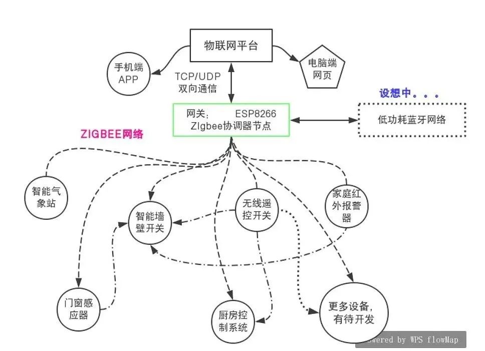
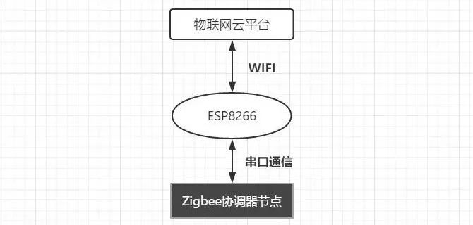
Wireless Communication Solution Before choosing, I had previously encountered Zigbee networking, which is also a commonly used networking method due to its low cost and simplicity. Here are several reasons for choosing this network:

ESP8266 and Zigbee Networked Wall Switch Modification

Zigbee networks are indeed good. If you don’t want to learn the complex transmission theory and programming of Zigbee communication chips, you can choose to purchase ZigBee modules. For example, the small serial-to-Zigbee module below is convenient for microcontroller communication.
ESP8266 and Zigbee Networked Wall Switch Modification

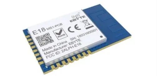
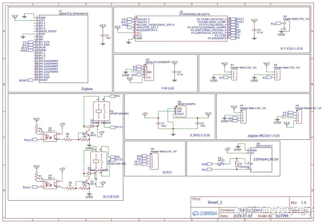
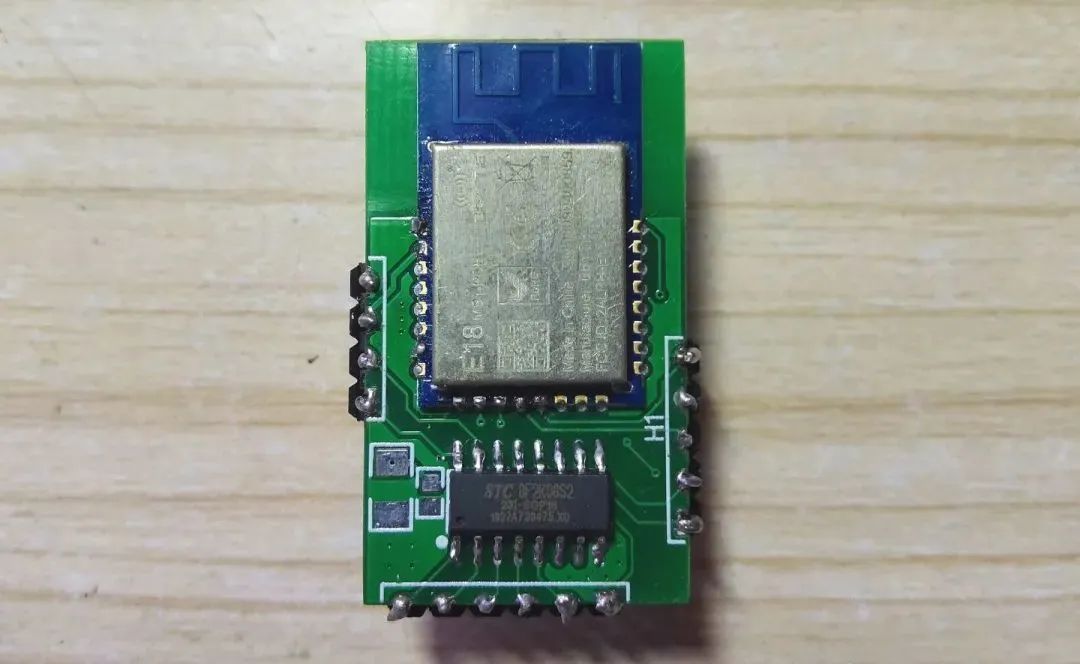
Speaking of modularity, a core control board is needed. Essentially, it integrates the microcontroller and the purchased Zigbee module onto one circuit board, while reserving various interfaces to facilitate later adaptation to various devices. This way, a single circuit board can be used for various smart home devices.

After drawing the schematic and PCB, the finished product became clear:
ESP8266 and Zigbee Networked Wall Switch Modification

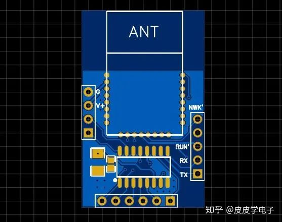
The soldered finished product is as follows:

ESP8266 and Zigbee Networked Wall Switch Modification

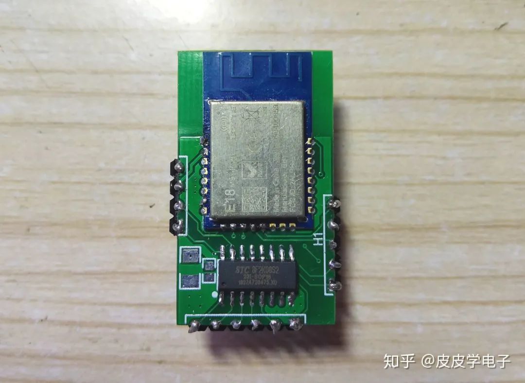
This will become the core control board for all my future smart home solutions.

After completing the core board, the gateway became the next focus because it controls and communicates with all smart devices in the home, including connecting to the Internet to transmit data. The gateway serves as a central control unit for the home, linking to the Internet and connecting to the Zigbee small communication network. I believe that ESP8266 is a good solution for this, as it supports Arduino IDE programming, which is great news for those who are not familiar with network communication protocols. With Arduino programming, powerful library functions can be used to achieve the desired functionality.
ESP8266 and Zigbee Networked Wall Switch Modification

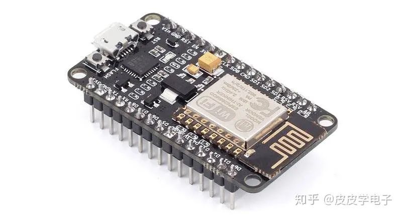
Everyone must be very familiar with the ESP8266, and I happen to have one on hand, so it fits perfectly.

I need to program the ESP8266 on-chip and call its serial port to communicate with the Zigbee module. When the Zigbee node receives data sent from other devices, the ESP8266 can process it or upload it to the cloud platform via WiFi. This is the overall design idea.
ESP8266 and Zigbee Networked Wall Switch Modification

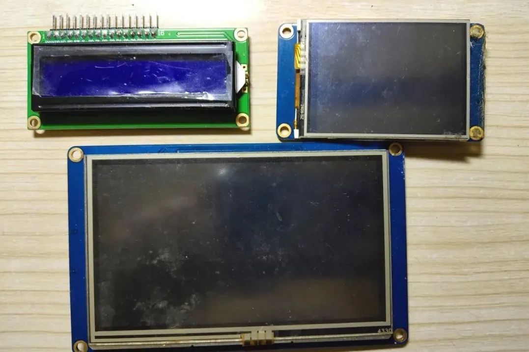
To facilitate the display of the gateway node’s status and the reading of related information for future debugging, I added a 4.3-inch serial touch screen to the gateway, making it easier to read information and perform debugging tasks.

ESP8266 and Zigbee Networked Wall Switch Modification

After completing the design of the Zigbee node core board and selecting the gateway hardware, the main components of the smart home system are now constructed.

Without detailing the programming yet, I will write the corresponding device interface program for the gateway after debugging each smart device. That is, after completing the development of a smart device, I will connect it to the gateway, allowing it to join the home Zigbee network for linked control or networked control. After all, the ZigBee module I am using only serves as a communication tool, while the actual functionality relies on the microcontroller on the core board. This development method is referred to as iterative development, which is a good solution for larger projects.

02

Production Section

Next is the design of the smart wall switch, which aims to make the wall switch in the home intelligent, allowing for network control, achieving scene linkage, and smart control.

I attempted to modify the traditional switch at home, but found that there was simply not enough internal space after disassembling it to complete the modification.
So I tried to buy a new switch online, looking for a wall switch with a larger space, and later found a manufacturer that specializes in producing touch smart switch casings. I purchased several touch wall switch casings, which have a larger internal space suitable for modification. Since it is a touch panel, I plan to use a touch module.

ESP8266 and Zigbee Networked Wall Switch Modification

As for the actuator, which acts as the original mechanical switch, I plan to use a relay to replace it. The relay allows me to control the on/off of 220V AC voltage using signals output from the microcontroller, providing good isolation and insulation performance.

ESP8266 and Zigbee Networked Wall Switch Modification

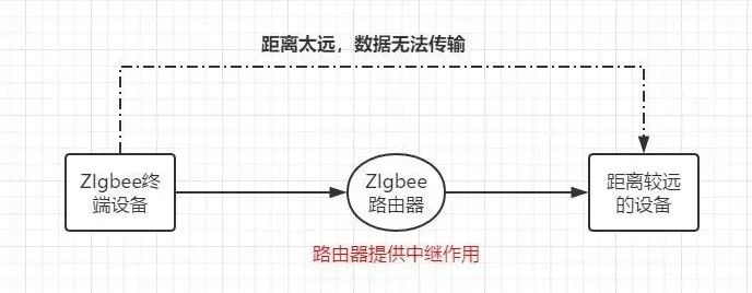
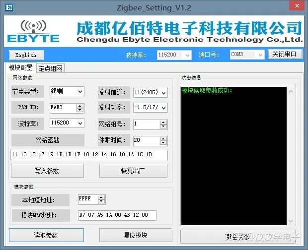
For the smart switch node, I configured the Zigbee module as a router node. The benefit of this is that the wall switch also acts as a router, assisting some remote terminal nodes in completing multi-hop data transmission. For example, if I want to use a wireless switch in the bedroom to control the light at the front door, directly sending data to the smart switch at the front door may fail due to insufficient signal strength. In this case, adding a router node in the living room allows the wireless switch’s signal to transmit to the smart switch at the front door.

ESP8266 and Zigbee Networked Wall Switch Modification

During normal operation, I configured the microcontroller to idle mode to save power. However, in idle mode, the microcontroller cannot correctly and timely detect the pressing of the touch button, so I used the external interrupt of the microcontroller to detect the touch button. When the touch button is pressed, the microcontroller detects the level change, triggers the interrupt, and wakes up the microcontroller to execute the relevant instructions.
ESP8266 and Zigbee Networked Wall Switch Modification

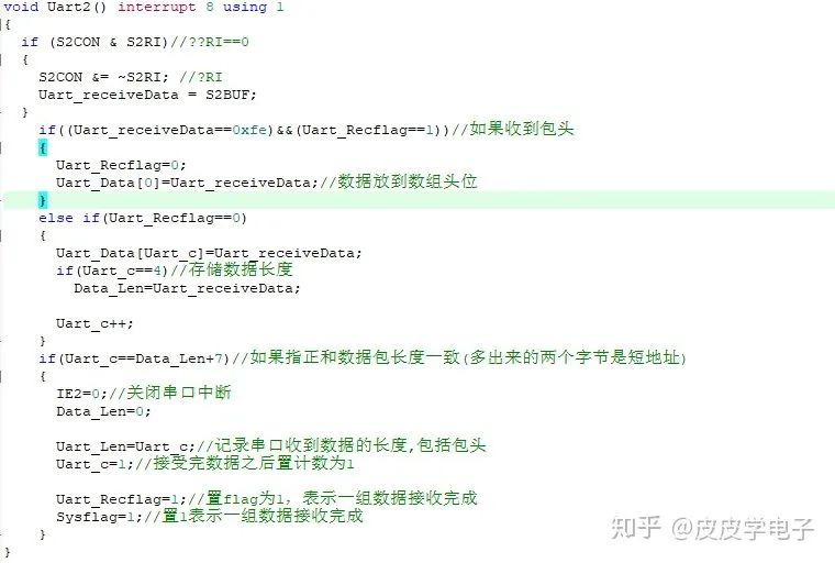
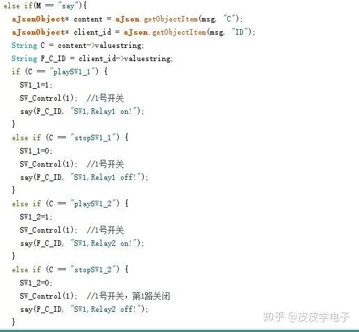
When the Zigbee module receives data from the smart gateway (e.g., closing or opening the switch), the output data will also trigger a serial interrupt that wakes up the microcontroller, which will then execute the received instructions and subsequently return to idle mode.

ESP8266 and Zigbee Networked Wall Switch Modification

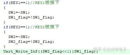
Additionally, to better monitor the status of each switch, after each switch action, the current status will be reported to the smart gateway, allowing the gateway to check the status of all switches in the home.

ESP8266 and Zigbee Networked Wall Switch Modification

Connecting the Zigbee coordinator node to the computer, turning on the power of the smart switch, you can see that every time I touch the switch, the corresponding relay will act, and the coordinator node’s serial port will output some data:

ESP8266 and Zigbee Networked Wall Switch Modification

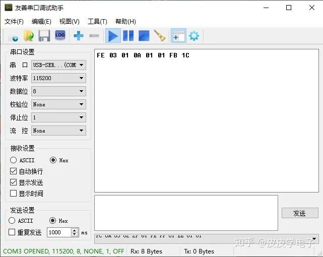
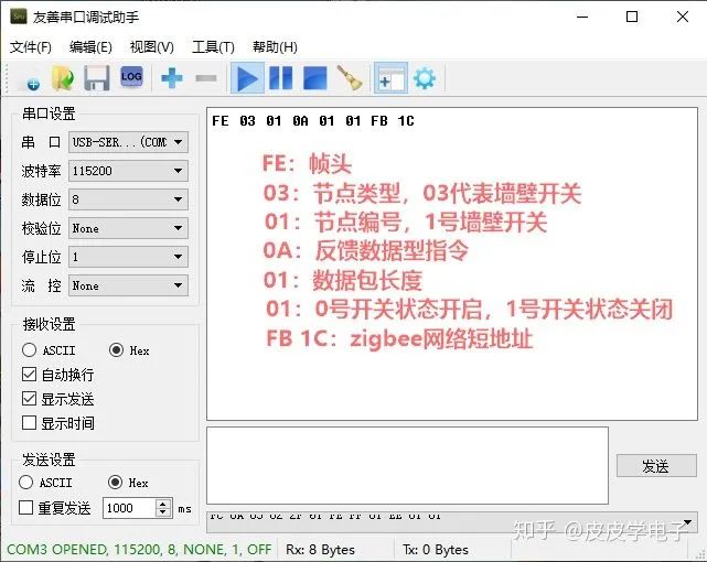
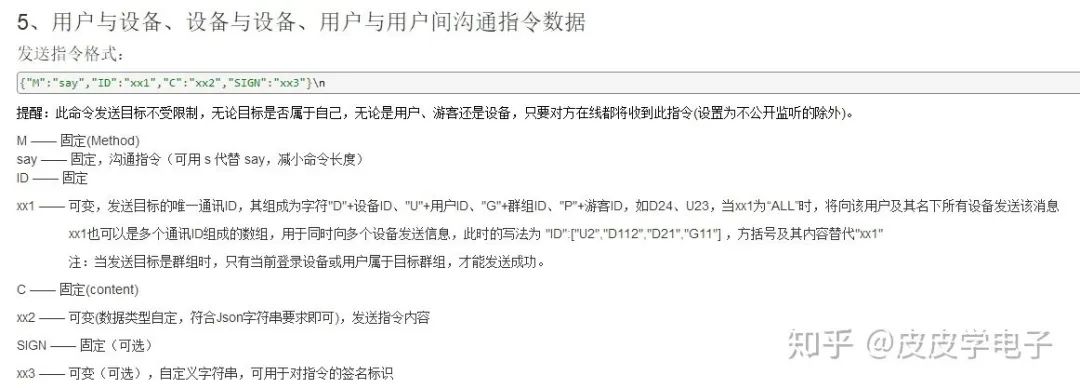
Below is an interpretation of a frame of data (this data packet structure is defined by me and is not the command structure required by the Zigbee module).

ESP8266 and Zigbee Networked Wall Switch Modification

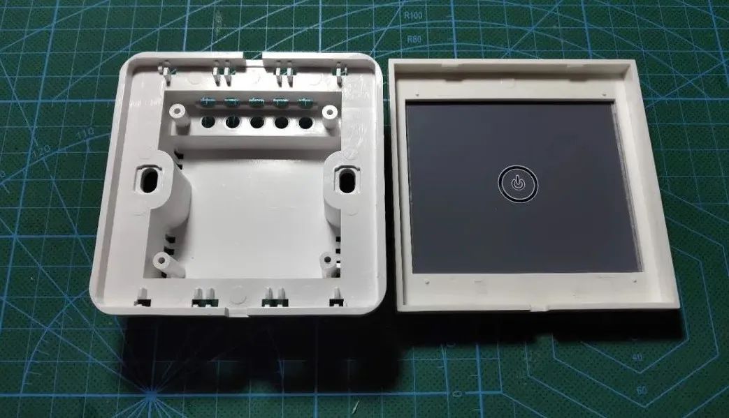
After testing, the smart switch achieved the functionality I wanted. Next, I will design the PCB board for the casing I purchased.

Design and Production of Smart Switch PCB: For the purchased casing, I first found a CAD drawing provided by the manufacturer, which marked some basic dimensions, making it easier for me to design a suitable PCB board.
After converting the circuit previously built on the breadboard into a schematic, the result is as follows:
ESP8266 and Zigbee Networked Wall Switch Modification
Click to enlarge

After converting to PCB files, and after simple component placement and wiring, the completed effect is as follows:

ESP8266 and Zigbee Networked Wall Switch Modification

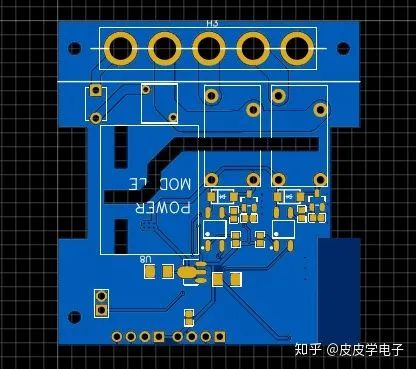
The AC high-voltage section and DC low-voltage section are separated by grooves to provide good anti-interference characteristics. The back side is designed for the positions of the Zigbee module and the microcontroller.

The effect after soldering is as follows:
ESP8266 and Zigbee Networked Wall Switch Modification

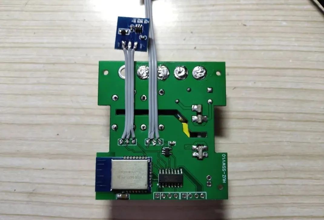
After installing the touch module, I used double-sided tape to stick the touch module onto the panel glass.

ESP8266 and Zigbee Networked Wall Switch Modification

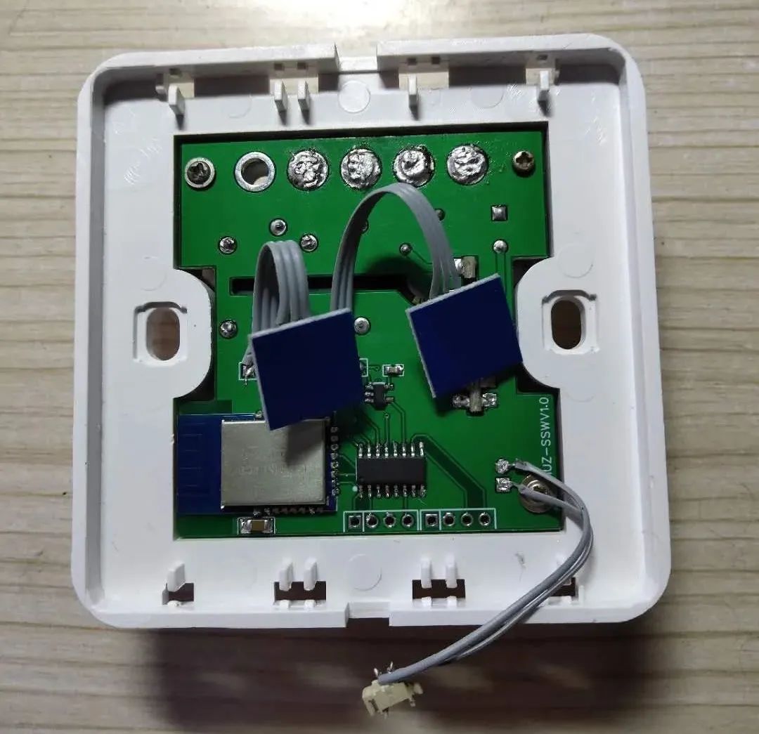
After programming, close the casing, and use labels on the back to indicate the definition of the connections for easy installation.

ESP8266 and Zigbee Networked Wall Switch Modification

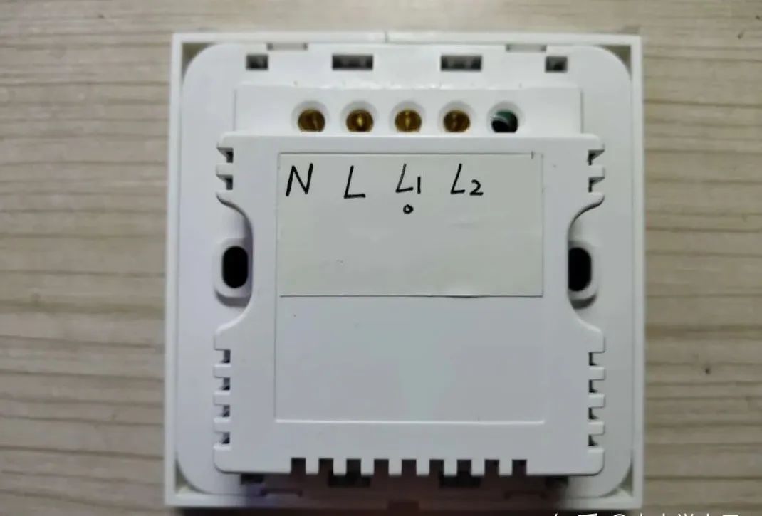
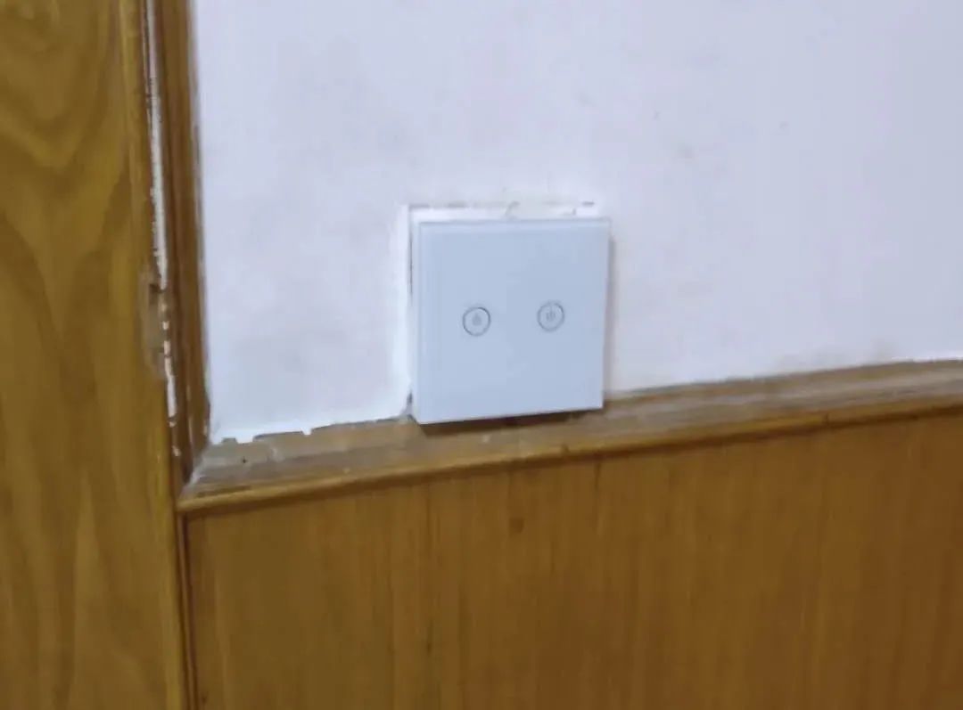
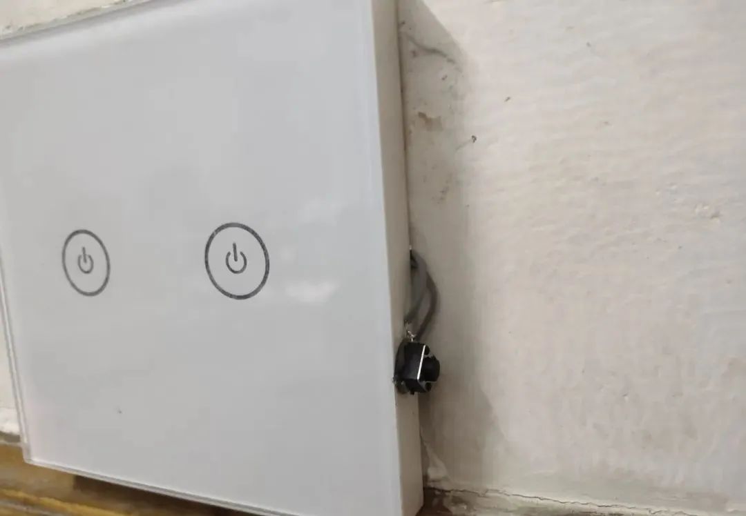
Use the smart switch to replace the traditional switch in the home.

ESP8266 and Zigbee Networked Wall Switch Modification

03

Writing the Corresponding Program for the Gateway

This part of the program mainly allows the gateway to receive control commands in JSON string format from the IoT platform, then decode and translate them, and finally inform the smart switch via the Zigbee network to initiate the corresponding actions. Therefore, the core of this is to receive the JSON string from the server and interpret its meaning.
Similarly, I still use the Arduino JSON library to handle this information. Referring to the communication protocol manual of the IoT platform, I found that the following format is used:
ESP8266 and Zigbee Networked Wall Switch Modification
Therefore, it is only necessary to interpret the instructions attached after the say command. Thus, a parallel structure using else if statements was quickly written, with the program judging each received string in order and sending the command to the smart switch if they match.
ESP8266 and Zigbee Networked Wall Switch Modification

Upload the program to the ESP8266 and start testing!

04

Comprehensive Testing

Install the smart switch in place, connect the power to the gateway, touch the touch switch, and the light can be turned on and off normally. Take out your phone, open the IoT platform, and press the button to turn on the light, and the light will turn on.
ESP8266 and Zigbee Networked Wall Switch Modification
Thus, the design of the wall switch, circuit construction, and use of network control have been completed. The remaining task is to add various linkage functions. Moreover, it supports various functional expansions (timed switches, linkage with human sensors, etc.), providing significant convenience to life.

05

Production of Wireless Remote Control Switch

Before going to bed at night, the wall switch is too far from the bed, making it inconvenient to turn off the light. Therefore, I plan to design a remote wireless switch that can control all smart devices in the home through pairing, similar to a stick-on switch. Below is the introduction to the design of the wireless remote control switch.

1) Circuit Design
As a terminal node in the Zigbee network, the wireless remote control switch needs to have a low-power operating mode. Therefore, according to the data sheet of the e18 Zigbee module I used, I configured it to sleep mode.
ESP8266 and Zigbee Networked Wall Switch Modification

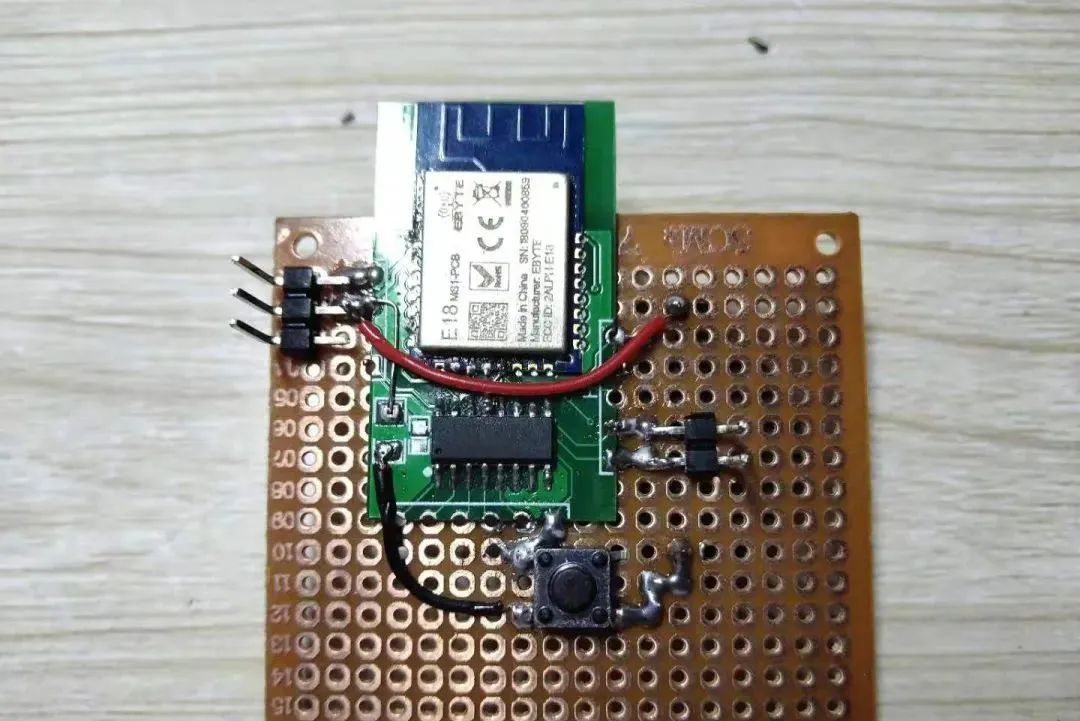
Take out the completed Zigbee minimum system board.

ESP8266 and Zigbee Networked Wall Switch Modification

The wireless remote control switch has a button for operation, so I soldered a push-button switch onto the minimum board module.

ESP8266 and Zigbee Networked Wall Switch Modification

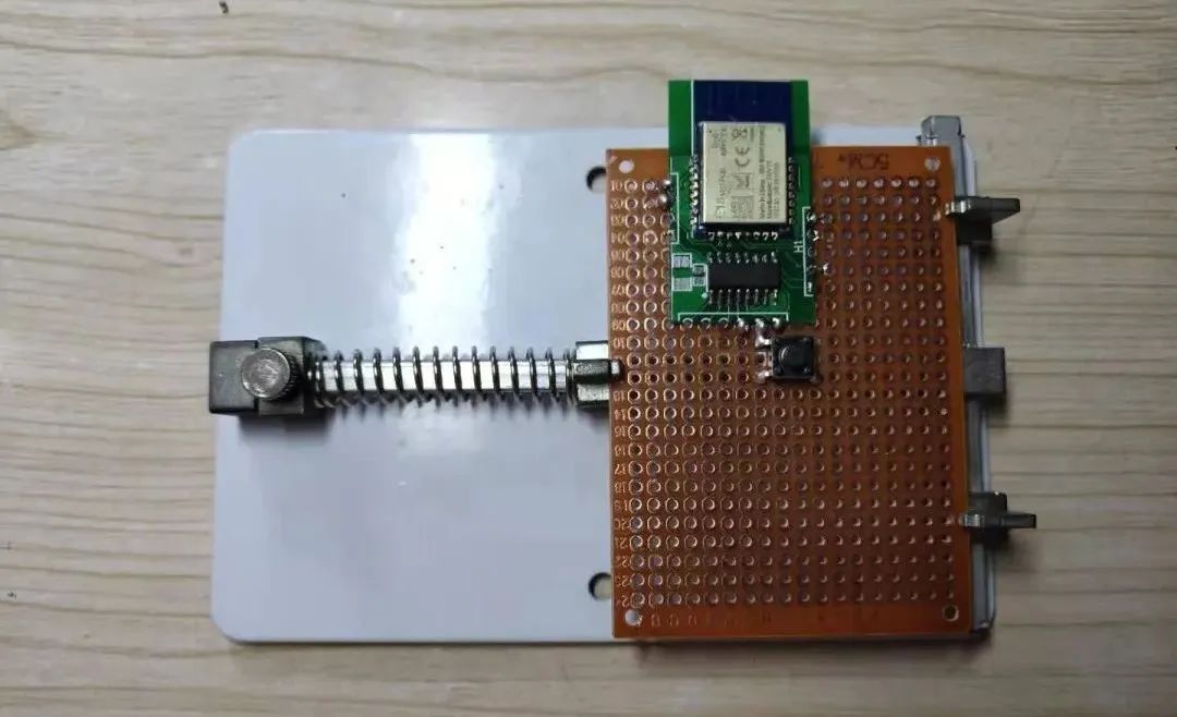
Additionally, I soldered the power line, using a button battery for power supply (the button battery is on the back).

ESP8266 and Zigbee Networked Wall Switch Modification

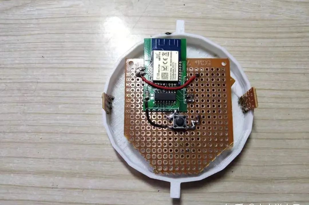
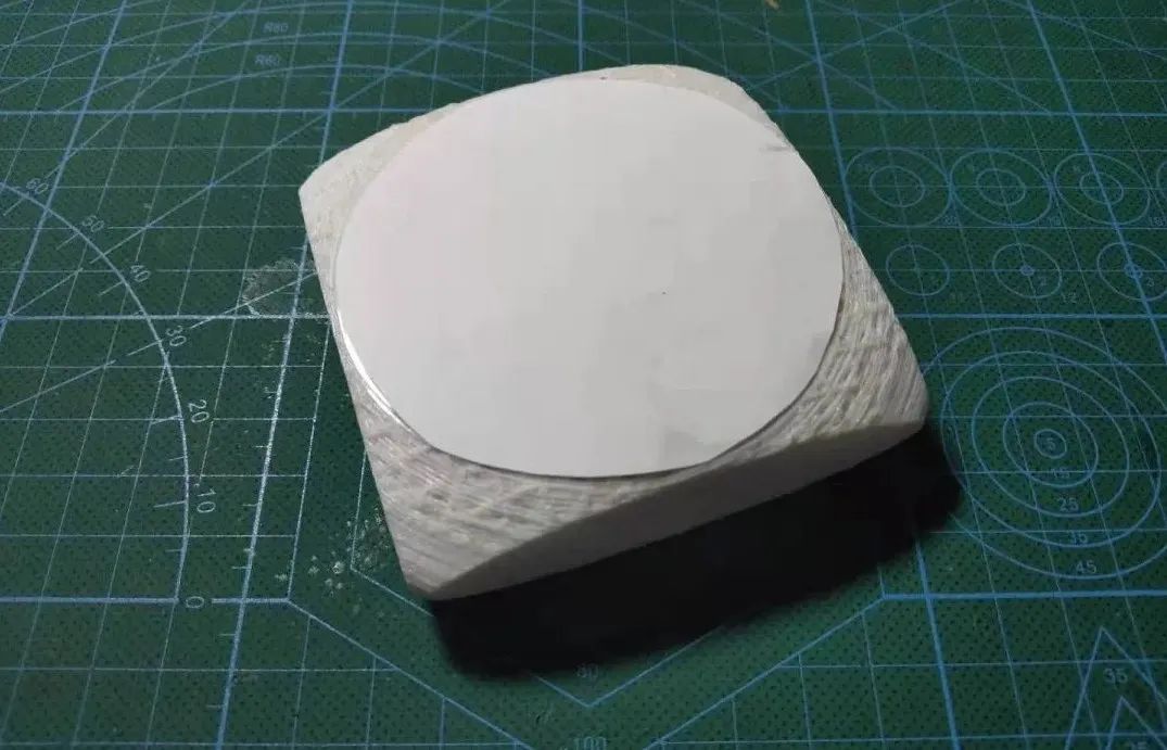
I used a 3D printer to print the casing (the printer wasn’t adjusted very well, so the print is somewhat rough), and I cut the board to fit inside:

ESP8266 and Zigbee Networked Wall Switch Modification

The assembled appearance is as follows:
ESP8266 and Zigbee Networked Wall Switch Modification

2) Configuration Corresponding to the Gateway

I drew a display screen interface:
ESP8266 and Zigbee Networked Wall Switch Modification

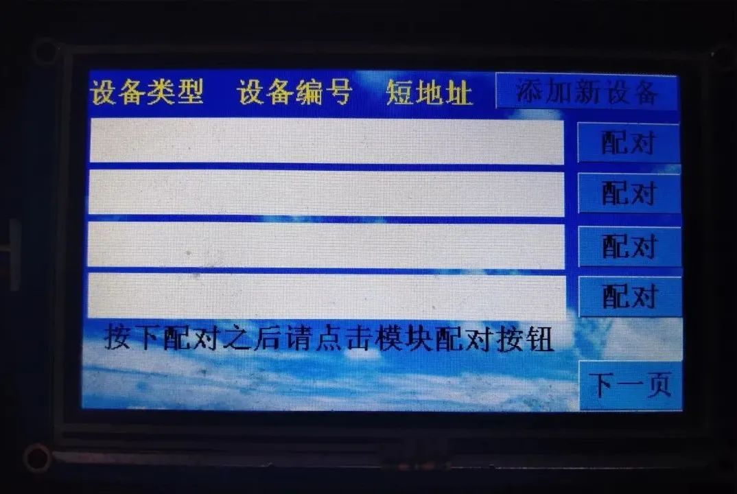
In this interface, press the pairing button on the wall switch:

ESP8266 and Zigbee Networked Wall Switch Modification

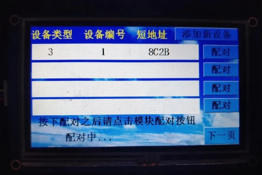
At this time, the display will show relevant information. Device number 1 will display on the first line, and so on. The part that exceeds one page will automatically scroll:

ESP8266 and Zigbee Networked Wall Switch Modification

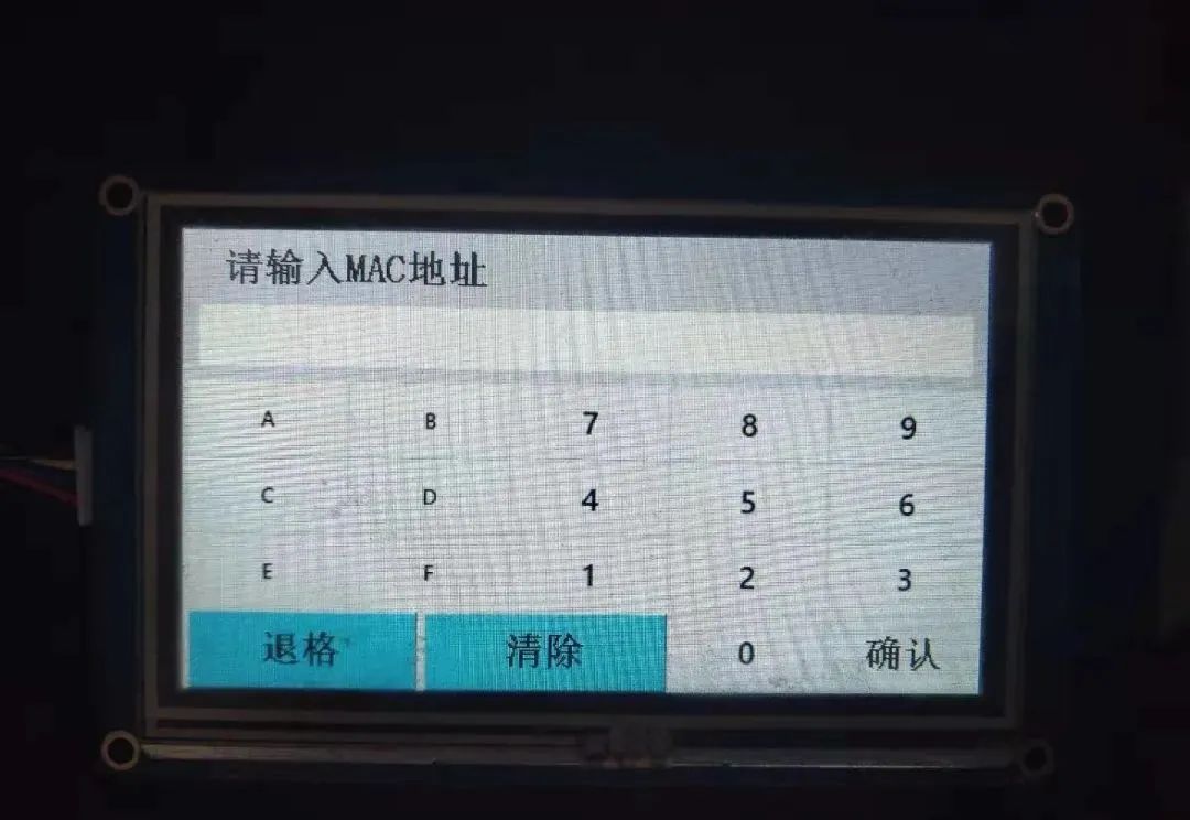
If the reset button is damaged, you can also use the MAC address addition method:

ESP8266 and Zigbee Networked Wall Switch Modification

Click the pairing button on the right side of the information, and the screen will display a prompt for pairing:

ESP8266 and Zigbee Networked Wall Switch Modification

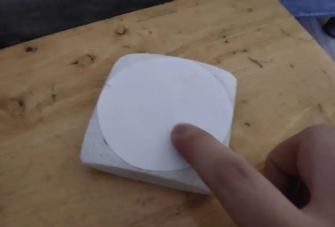
At this time, press the button on the wireless remote control switch:

ESP8266 and Zigbee Networked Wall Switch Modification

Then you will see the pairing success prompt on the display:

ESP8266 and Zigbee Networked Wall Switch Modification

At this point, you can control the light on and off using the wireless remote switch:

ESP8266 and Zigbee Networked Wall Switch Modification

The main principle behind this functionality is that the wireless switch remembers the short address of the wall switch, so every time the button is pressed, it sends data to the smart wall switch to control the on/off state. Later, this remote can also be set to control other switches, achieving one-to-many control.
Through the Zigbee network, I have achieved control over the wall switch at home. I will share more projects such as a weather station in the future.
Do you want to transform your home? But are you struggling with insufficient technical skills? Darwin recommends a course that solidifies your power supply fundamentals. The viewing method is as follows:
ESP8266 and Zigbee Networked Wall Switch Modification
END
ESP8266 and Zigbee Networked Wall Switch Modification

More practical project recommendations:

STM32 IoT Smart Home Project

Raspberry Pi + Compute Stick 2 for Real-Time Face Recognition Project

Building a Cloud Computing Platform for Embedded Development Boards

STM32 for the Simplest Air Mouse

Arduino Rubik’s Cube Robot

STM32 Version “AI Soul Painter”

STM32 Electronic Photo Album Production

STM32 + DDS Homemade Signal Generator

Remote Control of Home Appliances Using Raspberry Pi with Web Interface

STM32 “Cloud” Music Player

Raspberry Pi Remote Monitoring

Design of Glow Tube Clock Based on STM32

Homemade FPGA Minimum System Board (PCB can be directly made)

Building NAS with Raspberry Pi 4 for Easy Network Access

ESP32 Car Software and Hardware Practical Sharing

Achieving Creative Gesture Recognition with Only 79 Lines of Code

Using IoT + Electronic Ink Screen to Create Custom Display Screens

Creating a Pathfinding Robot Worth Over a Thousand with Just a Few Dozens

Holographic Display with Naked Eye, Visual Persistence POV Project

DIY Gesture Recognition Module

Practical Small Designs That Anyone Can DIY from Scratch

Raspberry Pi to Create a Smart Doorbell + Smart Door Lock with Video

Strangely! My Development Board Can Automatically Play Games

Homemade Breathing Machine

Recommended Reading:

Project Sharing | Electric Competition Series | Artificial Intelligence | Postgraduate Entrance Examination
Must-Know Knowledge Points | Graduation Design | Switching Power Supply | Job Seeking
We are Nimo, the founder of Darwin, who only talks technology and not flirting. The Darwin online education platform aims to serve professionals in the electronics industry, providing skill training videos covering popular topics in various subfields, such as embedded systems, FPGA, artificial intelligence, etc. It tailors layered learning content for different groups, such as commonly used knowledge points, breakdown assessments, electric competitions/smart cars/postgraduate entrance examinations, etc. Welcome to follow us.
Official Website: www.darwinlearns.com
Bilibili: Darwin
QQ Group: Group 1: 786258064 (Full)
Group 2: 1057755357
ESP8266 and Zigbee Networked Wall Switch Modification

Leave a Comment