01
Introduction
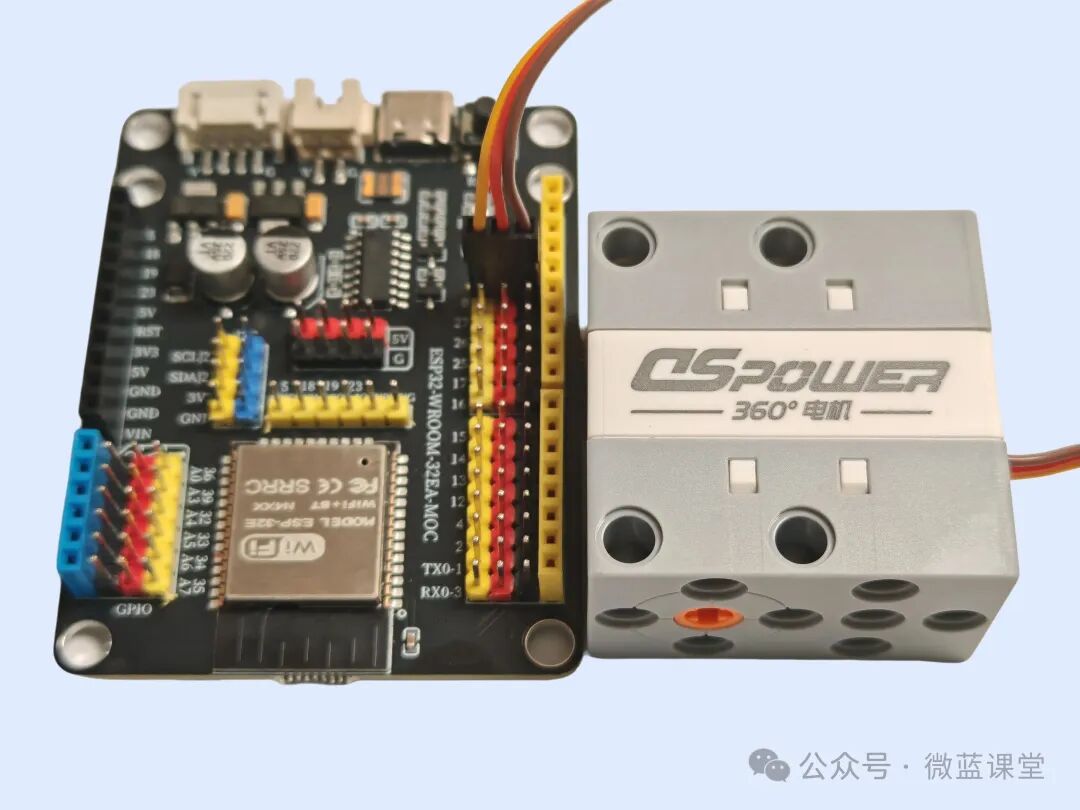
This PWM 360 motor is controlled by PWM signals. Compared to ordinary DC motors, it can control the rotation speed without additional drivers, has high torque, and features stall protection, but its rotation speed is not as fast.
02
Principle
The introduction and usage of PWM principles can be referenced in my previous article on PWM servos.
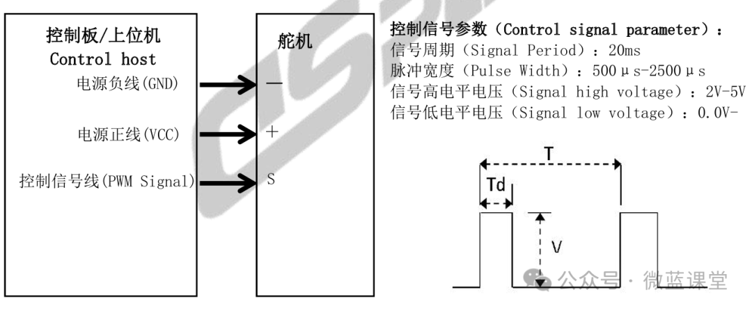
Motor parameters: 500μs~CCW counterclockwise; 1500μs~stop; 2500μs~CW clockwise
The PWM motor rotates based on pulse width signals. The signal period for this PWM servo is 20ms. When the pulse width is 1500μs, the motor stops rotating; when the pulse width is 500μs, the motor rotates forward at maximum speed; when the pulse width is 2500μs, the motor rotates backward at maximum speed.
03
Wiring
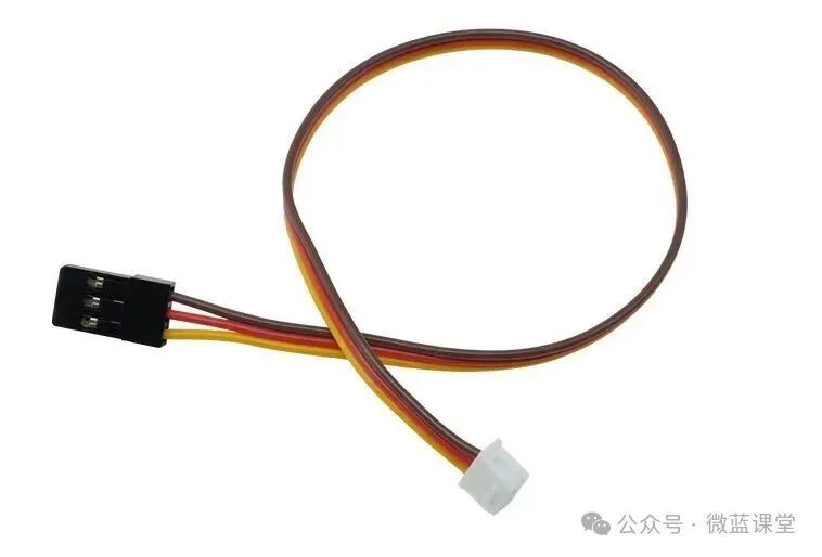
One end of the wire is a Dupont 3P connector, and the other end is a JST 2.54 3P connector, with three wires:
- G: Power negative, connect to GND, brown wire
- V: Power positive, connect to 3.3V, red wire
- S: Signal wire, connect to P0, yellow wire
04
Program
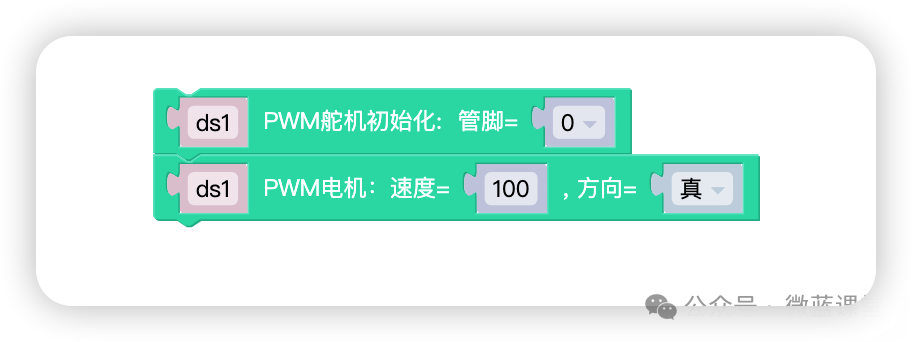
First, drag the PWM servo initialization module onto the canvas and modify it to the corresponding pin; then drag the PWM motor module onto the canvas.
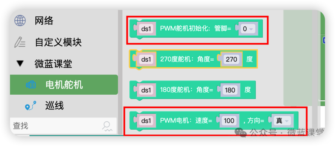
Click upload to see the PWM motor rotate. You can set the rotation direction and set the speed to 40. After clicking upload again, you will see the motor speed noticeably slow down; it does not support linear slowing.
If the motor does not rotate, try reversing the Dupont wire and reconnecting; the positive can be connected to 5V for faster rotation.
Students who need accessories can purchase them from my Taobao store under the same name.
 Follow me for more sharing|Weilan Classroom