The OLED screen (Organic Light-Emitting Diode Display) is a display technology that utilizes organic light-emitting diodes and is one of the commonly used display devices in embedded systems. It can display various characters, graphics, and images, including both Chinese and English. In embedded systems, the primary role of the OLED screen is to provide users with an intuitive interactive interface, displaying system status, operational results, and the information required by users.
1. Introduction to OLED Screens
There are many display devices, among which OLED displays are favored, especially by students working on graduation projects or course designs. Today, I will guide you through the OLED display. The 0.96-inch OLED screen is quite common in use, and we will take the 0.96-inch OLED screen as an example.
1.1 Searching and Purchasing the 0.96-inch OLED Screen
There are many websites to purchase displays, but for most university students or DIY enthusiasts, they often filter and buy through Taobao. We can search for OLED on Taobao’s homepage as shown below:
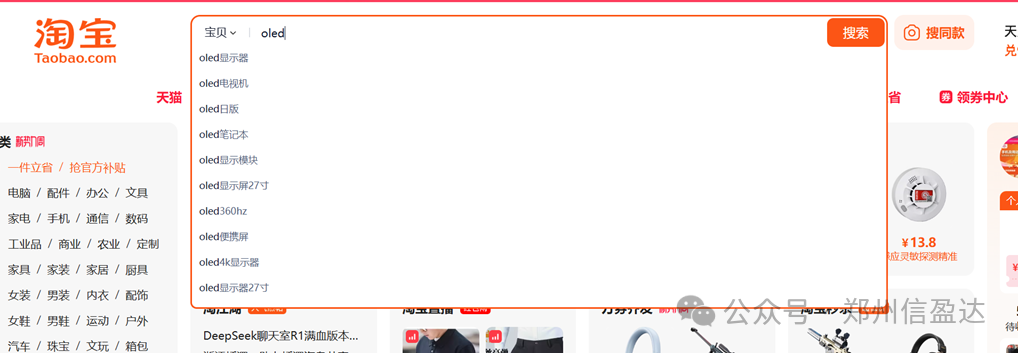
We find that it automatically pops up many prompt messages; we can directly click search without clicking on the recommendations, and the following interface will appear. There are quite a few stores, and the prices are not expensive. We can choose any store because the sensor is already quite mature. I suggest that you may also need to purchase other sensors, so you can choose a store that sells a variety of sensors you need.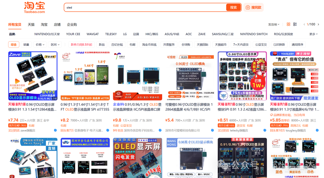 After selecting a store and clicking in, we find the following parameter information:
Check whether the OLED screen parameters meet your project requirements. If they do, place an order and then request some related materials from Taobao, which generally include basic code and documentation.
1.2 Product Overview
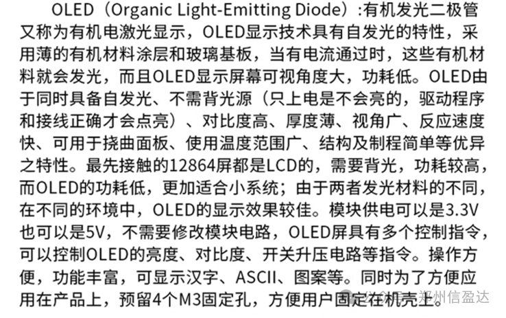
1.3 Advantages of the Product
1. Self-illuminating characteristics: Each pixel of the OLED screen can emit light independently without the need for a backlight. This means that when displaying black, the pixels are completely turned off, achieving true black and nearly infinite contrast.
2. High contrast: Due to self-illumination and pixel-level brightness control, OLED screens can exhibit extremely high contrast, with vivid colors and clear black and white.
3. Wide viewing angle: The viewing angle is broad, and there is no significant color distortion when viewed from the side, providing a consistent visual experience.
4. Low power consumption: Although it may not be more energy-efficient than LCDs when displaying bright scenes, it is overall more power-saving when displaying dark content because the pixels can be turned off directly.
5. Rich colors: OLED screens typically offer a wider color gamut, with color depth reaching 1.07 billion colors, higher than the approximately 20 million colors of ordinary LCDs, providing a more vivid visual effect.
As a developer or DIY enthusiast, we need to pay more attention to the relevant parameters of the screen. We can see from the product parameters:
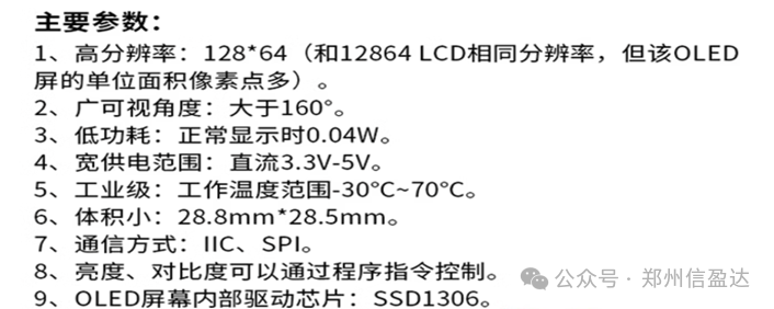
From the parameter data, we can find that the screen has two communication methods, and we generally choose SPI communication.
2. Communication Interface of the 0.96-inch OLED Screen
After understanding the relevant parameters of the 0.96-inch OLED screen and selecting the screen, we need to know how to connect it to the microcontroller and the display principle.
First, let’s look at how to connect the 0.96-inch OLED screen to the microcontroller.
Question 1: What are the pins of the 0.96-inch OLED screen, and what do they represent?
From the product parameters, we find that the 0.96-inch OLED screen has 7 pins:
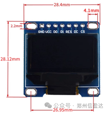
The pin descriptions are as follows: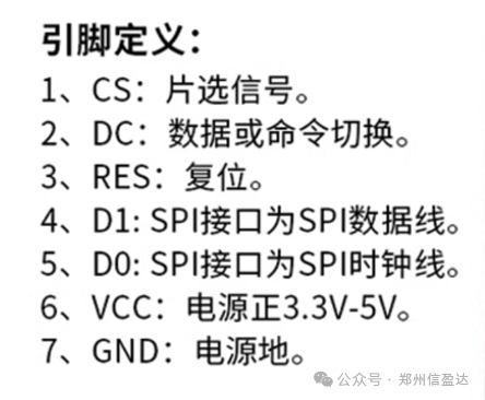
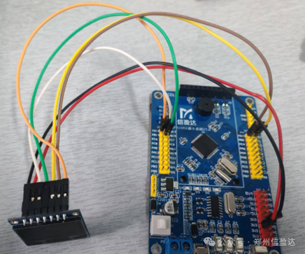
Question 2: How to connect the OLED screen pins to the microcontroller?
As shown in the figure below: Dupont wires can be used to connect the VCC pin to the 3.3V pin of the development board, connect the GND pin to the GND pin of the development board, and the RES, DC, CS, D0, D1 five pins can be connected to any available pins. Although SPI interface is chosen for communication with the microcontroller, our code can use GPIO ports to simulate SPI communication.
Question 3: Display principle of the screen
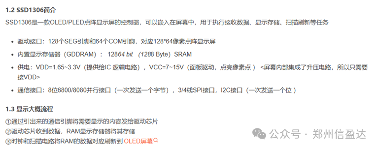
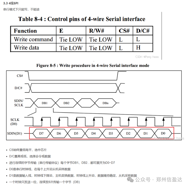
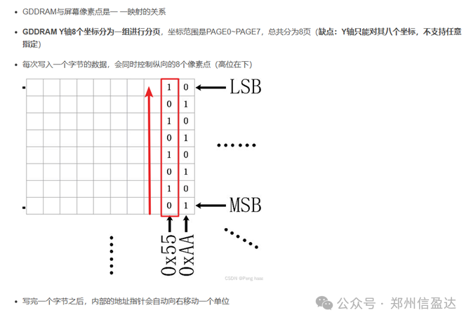
The 0.96 OLED screen uses the SSD1306 control chip, and the display principle can be obtained by requesting relevant documents from the vendor:
3. STM32 Driving the 0.96-inch OLED Display
Once we know how to drive the 0.96-inch OLED display, we can start practicing. Many people now use STM32 as the processing chip, so we will take STM32 driving as an example. The steps are as follows:
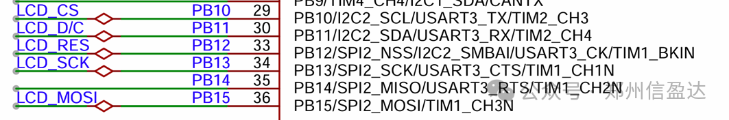
Step 1: Check the schematic to determine which pins of the 0.96-inch OLED display connect to which pins of the microcontroller.
Step 2: Initialize and configure the GPIO pins.
Step 3: Drive the OLED screen according to the product introduction to light up the OLED screen.
The specific implementation is as follows:
Step 1: Check the schematic to determine which pins of the 0.96-inch OLED display connect to which pins of the microcontroller.
Step 2: Initialize and configure the GPIO pins.
CS connects to PB10, DC connects to PB11, RES connects to PB12, D0 connects to PB13, D1 connects to PB15.
void GPIO_Config(void) //GPIO initialization function{ GPIO_InitTypeDef GPIO_InitStructure; RCC_APB2PeriphClockCmd(RCC_APB2Periph_GPIOD, ENABLE); //Enable D port clock GPIO_InitStructure.GPIO_Pin = GPIO_Pin_2; //Pin GPIO_InitStructure.GPIO_Mode = GPIO_Mode_Out_PP; //Push-pull output GPIO_InitStructure.GPIO_Speed = GPIO_Speed_50MHz; //Speed 50MHz GPIO_Init(GPIOD, &GPIO_InitStructure); //Initialize GPIOD3,6 GPIO_SetBits(GPIOD,GPIO_Pin_2); RCC_APB2PeriphClockCmd(RCC_APB2Periph_GPIOB, ENABLE); //Enable A port clock GPIO_InitStructure.GPIO_Pin=GPIO_Pin_1|GPIO_Pin_10|GPIO_Pin_11|GPIO_Pin_12|GPIO_Pin_13|GPIO_Pin_15; //Pins GPIO_InitStructure.GPIO_Mode = GPIO_Mode_Out_PP; //Push-pull output GPIO_InitStructure.GPIO_Speed = GPIO_Speed_50MHz; //Speed 50MHz GPIO_Init(GPIOB, &GPIO_InitStructure); //Initialize GPIOD3,6 GPIO_SetBits(GPIOB,GPIO_Pin_1|GPIO_Pin_10|GPIO_Pin_11|GPIO_Pin_12|GPIO_Pin_13|GPIO_Pin_15); } Step 3: Drive the OLED screen according to the product introduction to light up the OLED screen.
//OLED screen initialization function void OLED_Init(void){ GPIO_Config();//GPIO initialization function OLED_RST_Set(); delay_ms(100); OLED_RST_Clr(); delay_ms(200); OLED_RST_Set(); OLED_WR_Byte(0xAE,OLED_CMD); OLED_WR_Byte(0x00,OLED_CMD); OLED_WR_Byte(0x10,OLED_CMD); OLED_WR_Byte(0x40,OLED_CMD); OLED_WR_Byte(0x81,OLED_CMD); OLED_WR_Byte(0xCF,OLED_CMD); OLED_WR_Byte(0xA1,OLED_CMD); OLED_WR_Byte(0xC8,OLED_CMD); OLED_WR_Byte(0xA6,OLED_CMD); OLED_WR_Byte(0xA8,OLED_CMD); OLED_WR_Byte(0x3f,OLED_CMD); OLED_WR_Byte(0xD3,OLED_CMD); OLED_WR_Byte(0x00,OLED_CMD); OLED_WR_Byte(0xd5,OLED_CMD); OLED_WR_Byte(0x80,OLED_CMD); OLED_WR_Byte(0xD9,OLED_CMD); OLED_WR_Byte(0xF1,OLED_CMD); OLED_WR_Byte(0xDA,OLED_CMD); OLED_WR_Byte(0x12,OLED_CMD); OLED_WR_Byte(0xDB,OLED_WR_Byte(0x40,OLED_CMD); OLED_WR_Byte(0x20,OLED_CMD); OLED_WR_Byte(0x02,OLED_CMD); OLED_WR_Byte(0x8D,OLED_CMD); OLED_WR_Byte(0x14,OLED_CMD); OLED_WR_Byte(0xA4,OLED_CMD); OLED_WR_Byte(0xA6,OLED_CMD); OLED_WR_Byte(0xAF,OLED_CMD); OLED_WR_Byte(0xAF,OLED_CMD); OLED_Clear(); OLED_Set_Pos(0,0); } 4. Background Color Filling, Image Display, Chinese Character Display, and Character Display on the LCD Screen
Through the above steps, we have been able to light up the LCD screen. Next, we will implement the functional display of the LCD screen through the following steps.
Step 1: Create a bitmap for the image and call the image display function to achieve image display.
Step 2: Create a bitmap for the Chinese characters and call the Chinese character display function to achieve Chinese character display.
Step 3: Call the character display function to achieve character display.
The specifics are as follows:
Step 1: Create a bitmap for the image and call the image display function to achieve image display.
The steps to create a bitmap are as follows:
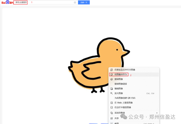
A. Download any image from Baidu (preferably a monochrome image, as the OLED screen is monochrome).
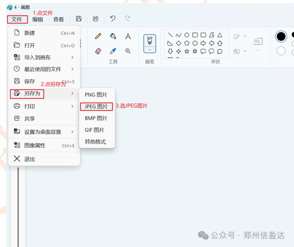
B. Open the downloaded image with the built-in paint software on your computer, find the resize and skew options to modify the image resolution, and save the modified image as a JPEG image on your desktop.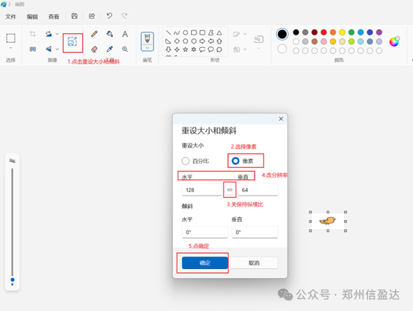
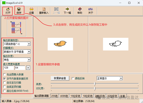
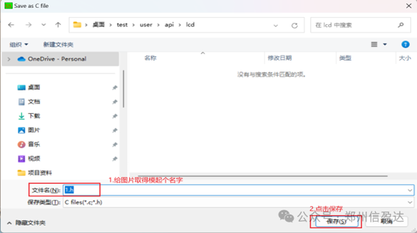
 C. Open the bitmap software, set the parameters for the bitmap software, and import the modified image.
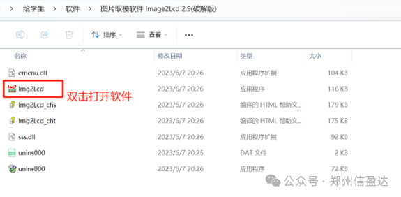
 Call the image display function in the main function, and write the corresponding parameters to display the image.
/****************************************************************************** Function Description: Display Image Input Data: x0,y0 starting coordinates x1,y1 ending coordinates BMP[ ] image array x range 0~127, y range 0~7 Return Value: None******************************************************************************/ void OLED_DrawBMP(unsigned char x0, unsigned char y0,unsigned char x1, unsigned char y1,unsigned char BMP[]){ unsigned int j=0; unsigned char x,y; if(y1%8==0) y=y1/8; else y=y1/8+1; for(y=y0;y<y1;y++) { OLED_Set_Pos(x0,y); for(x=x0;x<x1;x++) { OLED_WR_Byte(BMP[j++],OLED_DATA); } }} Step 2: Create a bitmap for the Chinese characters and call the Chinese character display function to achieve Chinese character display.
Steps to create a bitmap for Chinese characters:
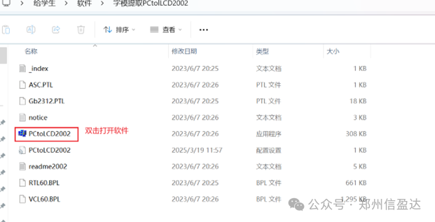
A. Open the Chinese character bitmap software and set it up.
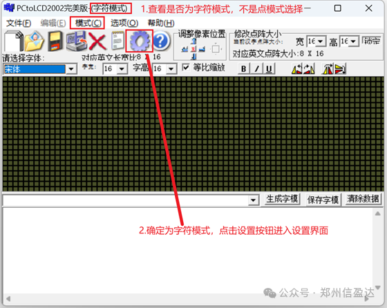
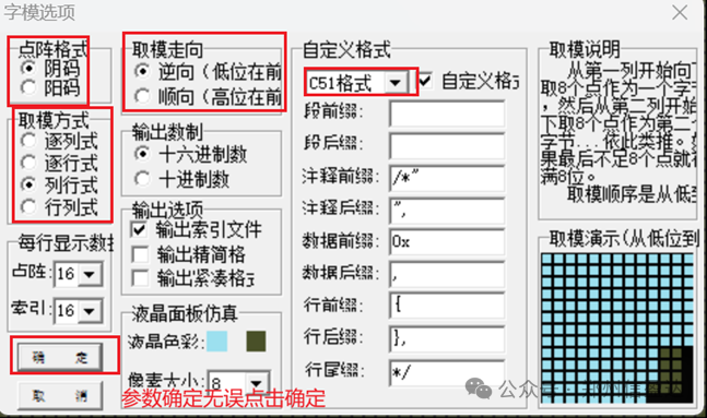 B. In the character bitmap input box, enter the Chinese characters to be generated, click the generate character bitmap button, and save the generated character bitmap into the code project.
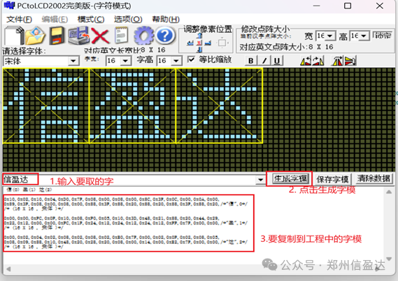 The character bitmap is placed in the oled.c file in the header file oledfont.h in the area for storing Chinese character bitmaps.
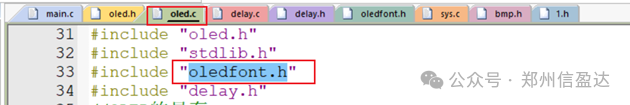 After storing, it looks like this:
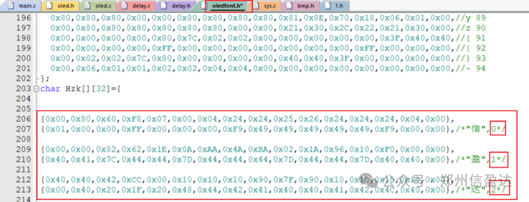 Call the Chinese character display function in the main function, and write the corresponding parameters to display the Chinese characters.
/****************************************************************************** Function Description: Display Chinese Character String Input Data: x,y starting coordinates no Chinese character bitmap order x range 0~127, y range 0~7 Return Value: None******************************************************************************/ void OLED_ShowCHinese(u8 x,u8 y,u8 no){ u8 t,adder=0; OLED_Set_Pos(x,y); for(t=0;t<16;t++) { OLED_WR_Byte(Hzk[2*no][t],OLED_DATA); adder+=1; } OLED_Set_Pos(x,y+1); for(t=0;t<16;t++) { OLED_WR_Byte(Hzk[2*no+1][t],OLED_DATA); adder+=1; } } Step 3: Call the character display function to achieve character display.
/****************************************************************************** Function Description: Display String Input Data: x,y starting coordinates *chr string to be displayed x range 0~127, y range 0~7 Return Value: None******************************************************************************/ void OLED_ShowString(u8 x,u8 y,u8 *chr){ unsigned char j=0; while (chr[j]!='\0') { OLED_ShowChar(x,y,chr[j]); x+=8; if(x>120){x=0;y+=2;} j++; } } Main function call:
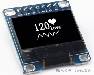
#include "stm32f10x.h" #include "stdio.h" #include "delay.h" #include "oled.h" //OLED screen header file #include "1.h" //Header file after image bitmap inline void JTAG_SWD_Config(void){ RCC_APB2PeriphClockCmd(RCC_APB2Periph_AFIO,ENABLE); GPIO_PinRemapConfig(GPIO_Remap_SWJ_JTAGDisable,ENABLE); } int main(){ JTAG_SWD_Config();//Disable JTAG function, enable SWD function Delay_Config();//System tick timer initialization NVIC_PriorityGroupConfig(NVIC_PriorityGroup_2); //Set NVIC interrupt group OLED_Init();//OLED screen initialization OLED_DrawBMP(0,0,128,8,(unsigned char *)gImage_1);//Display image OLED_ShowCHinese(72,0,0);// Display Chinese character 信 OLED_ShowCHinese(90,0,1);// Display Chinese character 盈 OLED_ShowCHinese(108,0,2);// Display Chinese character 达 OLED_ShowString(0,0,(u8*)"XYD");//Display character while(1) { } } The 0.96-inch OLED screen displays images, Chinese characters, and characters, as shown in the figure below: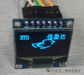 The above is the entire process of displaying images, Chinese characters, and characters on the 0.96-inch OLED screen driven by STM32. If you have any questions, feel free to scan the QR code below to leave a message in the live broadcast room for discussion.