Embedded Development: Core Components of Safety Architecture – SMU

In practical engineering, we often hear Alarm Alarm Alarm; for example, a watchdog timeout triggered an Alarm, or PLL anomalies triggered an Alarm… Why do we need these Alarms? Who manages these Alarms? When an Alarm occurs, how should it be handled? With these questions in mind, this article discusses the core component of the safety framework—SMU (Safety Management Unit).

Note: This article is based on TC375 discussions.

1. Why Do We Need Alarms?

We know that for a chip, in addition to the CPU (Central Processing Unit), there are a large number of peripheral modules that work together to achieve the expected functionality. Since these are independent hardware entities, there is a possibility of failure under certain operating conditions. To manage these failure scenarios, a unified overseer is needed to collect these exception messages, and then apply corresponding handling strategies to the exception modules. The overseer that collects exception information is the SMU, which notifies the SMU of exception messages through Alarms, as shown below:

Embedded Development: Core Components of Safety Architecture - SMU

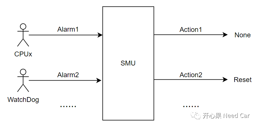
Thus, the purpose of designing Alarms is to monitor the chip’s operational status and to perform corresponding post-processing for fault states.

2. Who Manages the Alarms?

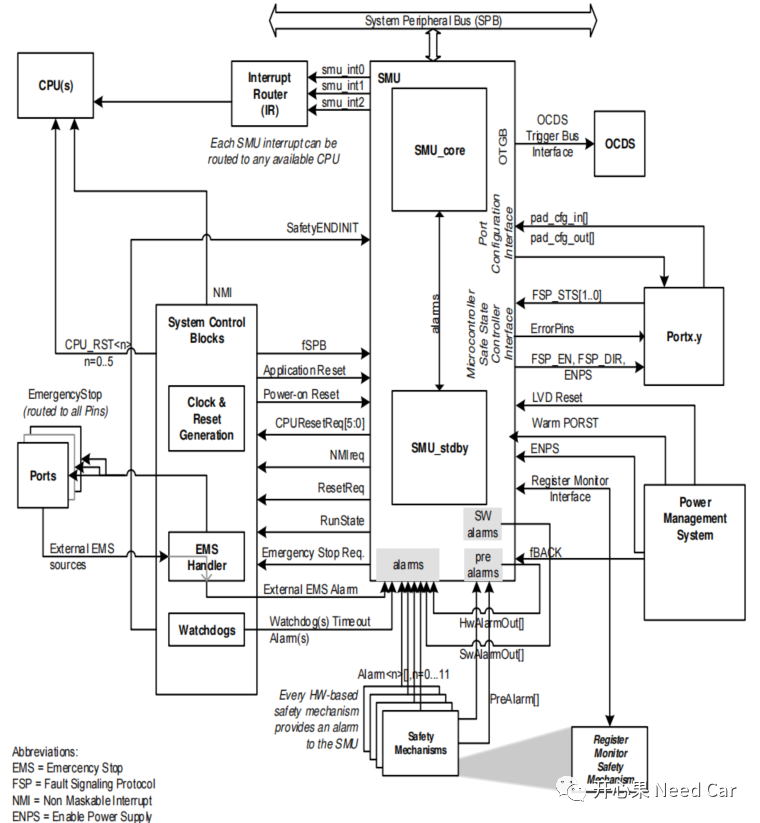
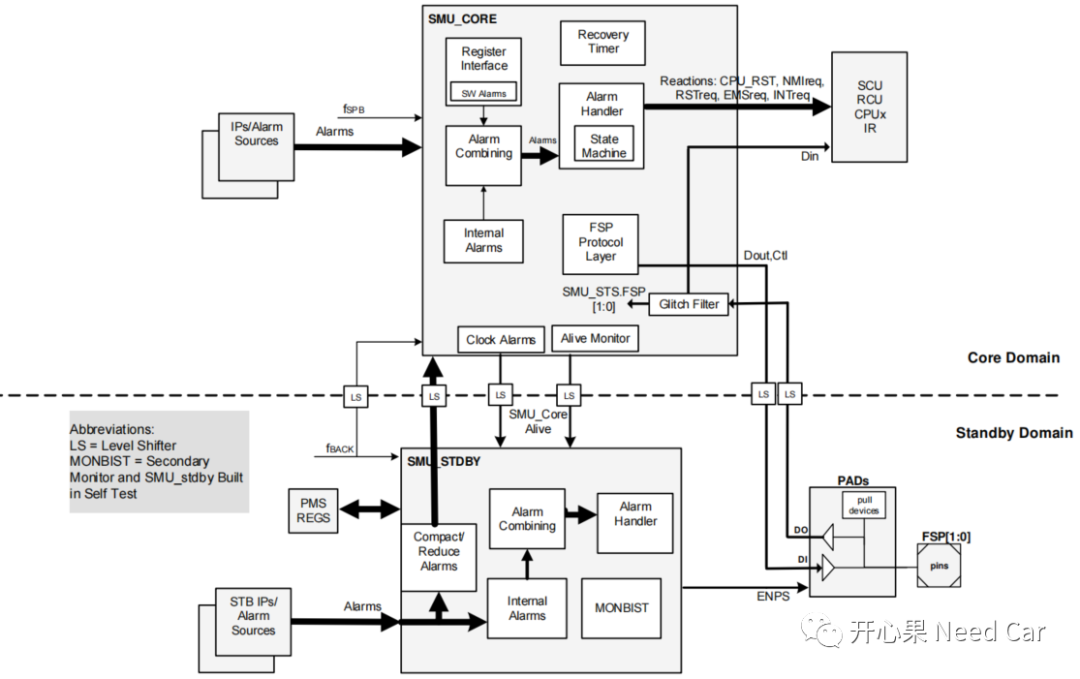
The previous section has already provided the answer: Alarms are managed by the SMU, which interacts with other module interfaces, as shown below:

Embedded Development: Core Components of Safety Architecture - SMU

The SMU mainly includes: SMU_CORE and SMU_STDBY, and the architecture of the SMU is shown below:

Embedded Development: Core Components of Safety Architecture - SMU

SMU_CORE focuses on handling hardware monitoring alarms and Safety-related Alarms, while SMU_STDBY focuses on clock alarms, power alarms, and temperature-related alarms.

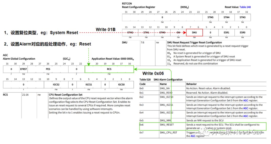
3. How to Handle Alarms When They Occur?

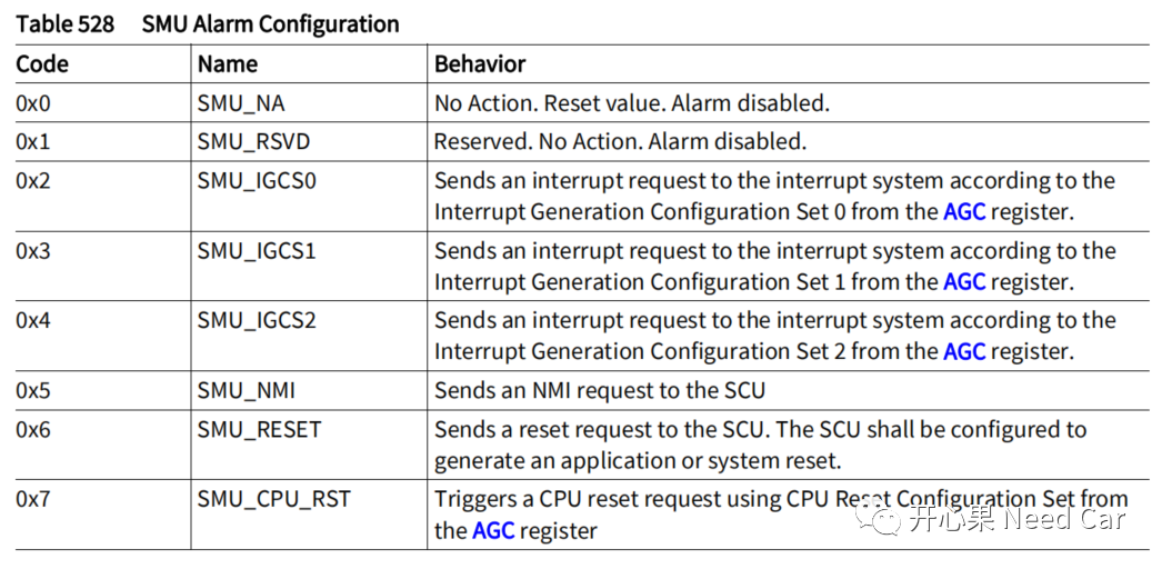
According to the reference manual, upon detecting an Alarm, various types of actions can be triggered, as described below:
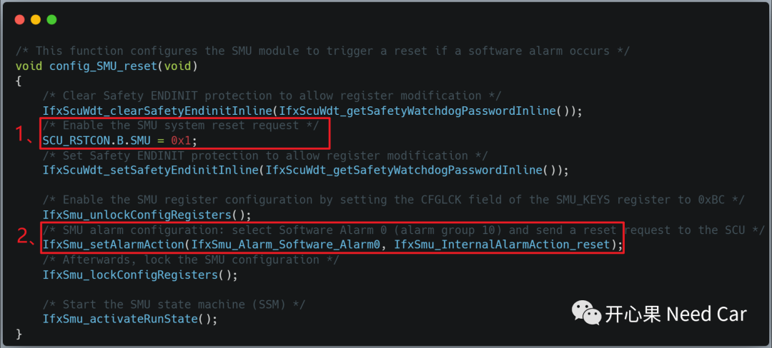
Embedded Development: Core Components of Safety Architecture - SMU

In practical engineering, triggering a Reset is the most common alarm handling behavior. Note that there are various types of system Resets, and the types of resets that an alarm can generate include Application Reset and System Reset. If SMU_RESET (System Reset) is chosen, the software must be configured in advance for the reset type, as described in the following software setup:

Embedded Development: Core Components of Safety Architecture - SMU

Note: If choosing Reset handling, it is recommended to select System Reset, as it is more thorough compared to Application Reset, making program initialization more robust.
Corresponding software processing is illustrated below:

Embedded Development: Core Components of Safety Architecture - SMU

4. Source Code

Based on the official example, the source code link is as follows:
https://github.com/Kaixinguo2021/Tasking_TC375_SMU_Reset_Alarm.git

Previous Highlights

Summary of previous exciting articles on Autosar: 1~70
Summary of previous exciting articles on Autosar: 71~100
Summary of previous exciting articles on Autosar: 101~150

Summary of previous exciting articles on Autosar: 151~200

Summary of previous exciting articles on Autosar: 201~251

Autosar EcuM: A Brief Analysis from APP Running to POST_RUN

How to Package Source Files (*.c) into Static Library Files (*.a) Based on HighTec

Diagnostic Basics: How Much Do You Know About NRC0x78 (Pending) Issues?

Overview of DDS and the DCPS Model

Engineering Issue: Functional Failure Caused by Network Status Desynchronization During ECU Sleep

Click below to follow and discuss Autosar/Embedded systems. If needed, contact the author to join the group for more professional answers.

Leave a Comment