If you don’t want to miss my updates, remember to check the public account in the upper right corner and set it as a star, take down the star and give it to me.


Compiled by: Wang Tongxue
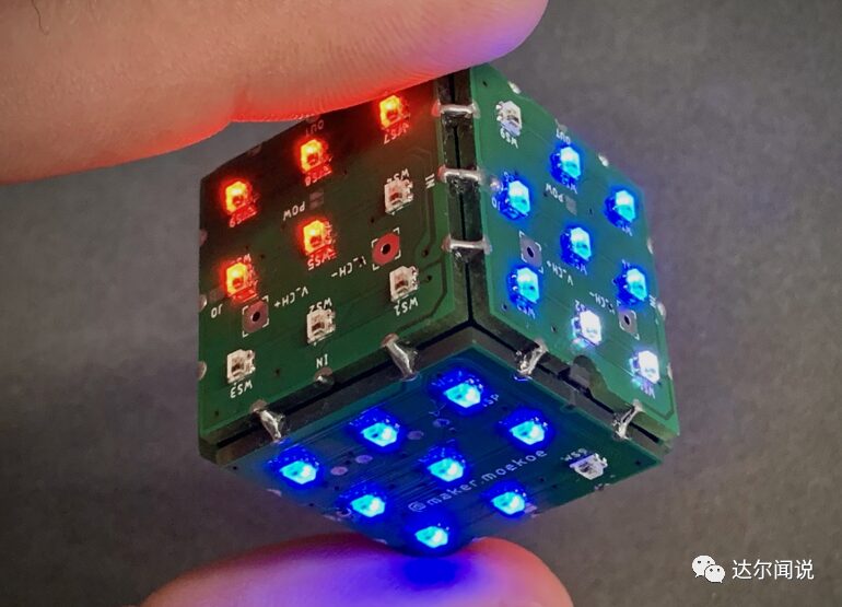
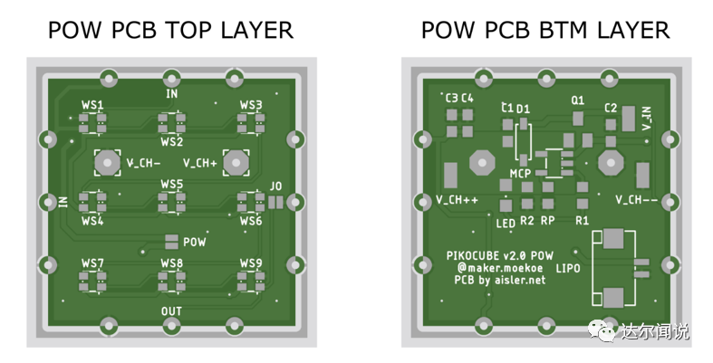
LED dice schematic and PCB were drawn using Eagle. To avoid making the cube too large, only two different PCBs were designed: the power board and the MCU control board. Both PCBs are square with a dimension of 25mm x 25mm.

The power board has a charging circuit and a lithium battery socket, while the MCU control board has the main control chip, ADXL345 gyroscope, and necessary power management circuits. All LEDs draw power directly from the lithium battery, and the MCU is powered by the LDO MCP1700, while the lithium battery charging chip is the MCP73831. There is one complete power board and MCU board (i.e., all components soldered on both sides), while the other 4 PCBs are power boards with only LEDs soldered.
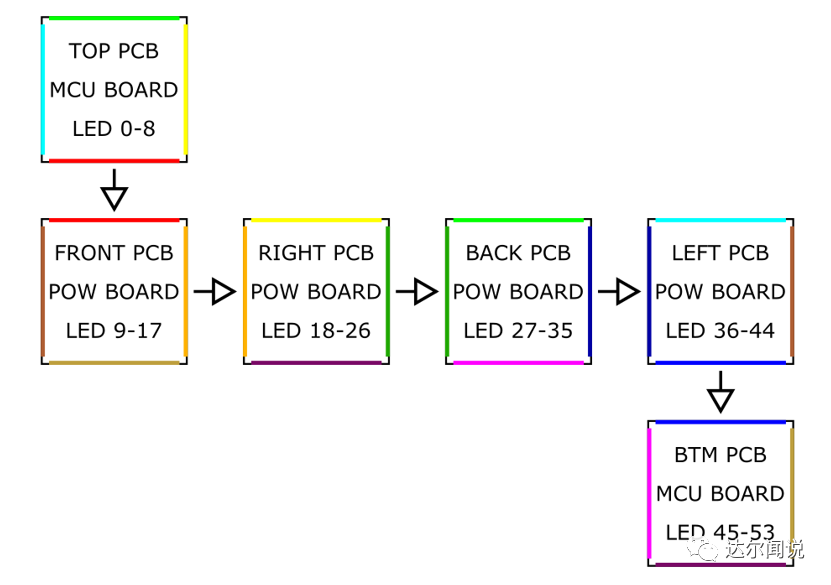
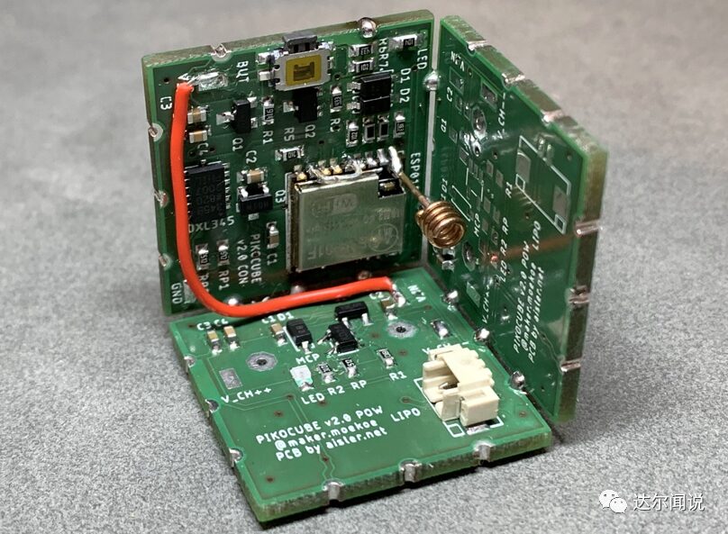
The uniqueness of these PCBs lies in the serrated holes on both sides, with three through holes on each side (cut in half for easy soldering for electrical connections, as shown in the image). On one hand, these holes make the physical object look more like a cube and keep everything in place; on the other hand, they transmit power signals and WS2812 control signals, distributing the three signals + 5V, GND, and LED control signals throughout the cube. The sequence of the PCBs is shown in the figure below. This is a flat layout of a cube, where edges of the same color indicate they are connected in the physical object. Arrows indicate the direction of WS2812 control signal transmission.
Assembling the cube is not easy, but to make it easier, a small soldering aid tool is used to solder at least three of the six PCBs together. Doing this twice will yield two PCB edges, and once everything is normal, they must be connected. Before soldering the lithium battery socket, make sure to solder the three PCBs together. Otherwise, you will have to modify the holes in the .stl file to fit the battery socket.
When the dice starts working, WiFi is not enabled to save some power, which is called modem-sleep. Checking the ESP datasheet shows that the MCU consumes only 15mA in modem-sleep mode, while it requires 70mA in normal mode, making this mode suitable for battery-powered devices. Therefore, before calling the setup function, the following code is needed:
void preinit() { ESP8266WiFiClass::preinitWiFiOff(); }
More Practical Project Recommendations:
STM32 IoT Smart Home Project
Project Sharing | Step-by-Step Face Recognition with MATLAB + Raspberry Pi
Raspberry Pi + Compute Stick 2 for Real-Time Face Recognition Project
Building a Cloud Computing Platform for Embedded Development Boards
STM32 Realizing the Simplest Air Mouse
Arduino Rubik’s Cube Robot
STM32 Version of “AI Soul Painter”
STM32 Electronic Photo Album Production
STM32 + DDS Homemade Signal Generator
Using Raspberry Pi and Web Interface to Remotely Control Appliances
STM32 “Cloud” Music Player
Raspberry Pi Remote Monitoring
Design of Neon Tube Clock Based on STM32
Homemade FPGA Minimum System Board (PCB can be directly made)
Setting Up NAS with Raspberry Pi 4 for Easy Hard Drive Networking
ESP32 Car Hardware and Software Practical Sharing
Only 79 Lines of Code to Achieve Unlimited Creative Gesture Recognition
IoT + Electronic E-Ink Screen to Create Custom Display
Build a Value Over a Thousand Pathfinding Robot for Dozens of Yuan
Glasses with No-Eye 3D Holographic Display, Visual Persistence POV Project
DIY Gesture Recognition Module
Practical Small Designs that Can Be DIYed with Zero Basics
Raspberry Pi to Create a Smart Doorbell + Smart Lock with Video Capability
Strange! My Development Board Can Automatically Play Games
Homemade Breathing Machine
ESP8266 + Zigbee Network Transformation of Wall Switch
Wireless Home Monitoring System
DIY Bionic Arm, a Tool to Free Your Hands
Handmade Air Purifier, All Design Materials Open Source
Tech Toys: Remotely Controlled Bluetooth Artillery
Using ST Sensors to Create LittleBee Monitoring System, Letting Bees “Talk”
Homemade Cat Petting Device
STM32 + Raspberry Pi to Achieve 6s Rubik’s Cube Robot
Blindly Modifying Drone Controller, DIY “Foam” Drone
Making an Intelligent Relay Without Arc Using STM32
Only 5 Components to Make a Practical New Model Necklace
The Simplest Method for Heart Rate Measurement (Suitable for Secondary Development)
Cracking the Magnetic Levitation Globe
The Amazing Light Can Transmit Video? Revealing the Production Process
STM32 Homemade Smart Watch 60FPS Animation
Paying Tribute to Classic Radios, Observing the Production Process
DIY Third Eye: “Special” Glasses with Bluetooth/OLED/Lens Functionality
Homemade Solar Charger that Tracks Maximum Power Point
No-MCU Night Vision Goggles, Just Connect Wires
The Right Way to DIY a Flow Meter, Interest Modifier
Homemade High-Difficulty Racing Timer (Lap Counting/Thermal Printing)
Recommended Reading: