MAKER:ChrisParkerTech/ Translated by:Fun Endless
We have introduced many different versions of LED display projects, such as: “Creating Colorful LED Balls with ESP32”, “Raspberry Pi + Dot Matrix Bitcoin Tracker”, and “Audio Pulse: Creating a 32-Band Audio Spectrum Dot Matrix“. LED matrix projects always provide a stunning visual experience.
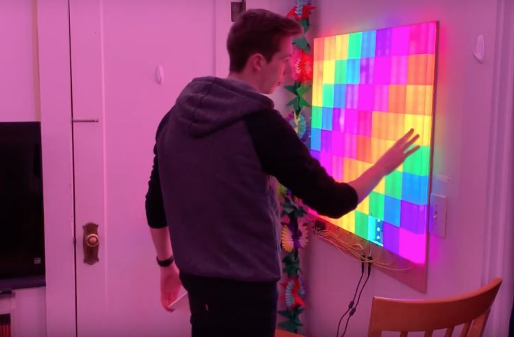
This issue’s LED project is an interactive LED display wall controlled by Arduino and assembled with a 3D printed shell.The overall project is not expensive and has strong human-computer interaction, hoping to inspire you.
Material List
Arduino Mega x 1WS2812b Addressable LED Strip x SeveralTactile Switch x 645V 10A Power Supply x Several18 Gauge Wire x SeveralWhite PLA Filament x Several4’x 4’x 1/4” MDF x SeveralSolder x SeveralHot Glue x Several
3D Printing the Wall
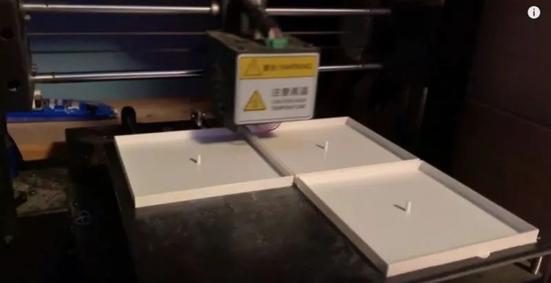
In this part, you need to 3D print 64 pieces of 8×8 grid. Each wall block is a 3.6-inch square with a thickness of 1 inch. The edges of the wall will have some notches for easy wiring of the LED strips and buttons. Printing three blocks at a time takes about 5.5 hours. Completing all will take about 120 hours. So you can work on other parts simultaneously.
All 3D printed STL files can be downloaded from the project file library:https://make.quwj.com/project/192
Wiring the LED Strip
The WS2812b LED strip is used because it can be individually addressed, and each LED on the strip can be programmed with different colors and brightness. They can also pass data from one pixel to the next. These functions can be achieved with just one data pin from the Arduino. The pixel density of the strip is thirty LEDs per meter.

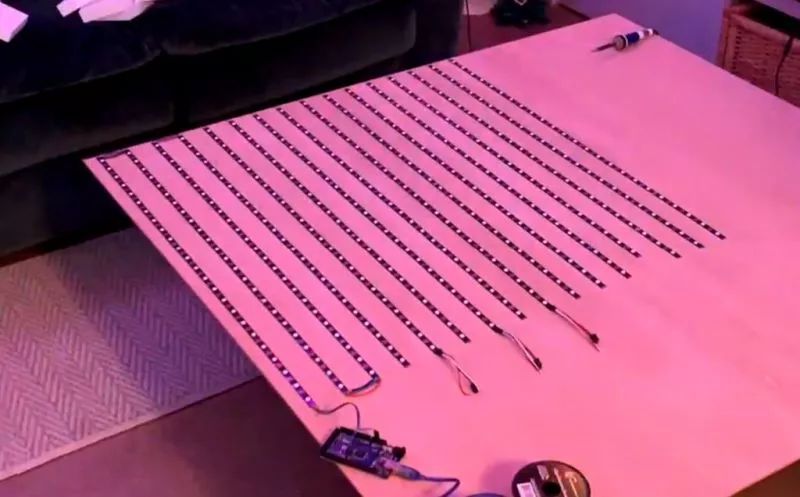
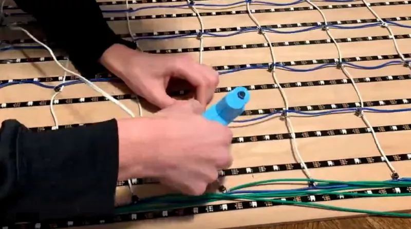
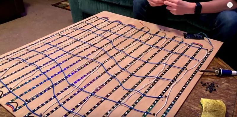
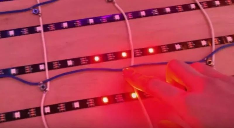
Each wall block installs six LEDs, three in a row, for two rows.Therefore, I cut these strips into sixteen segments, each with twenty-four LEDs.Then glue these strips onto the wooden board.Make sure to clean the board before securing the strips.
Also, pay attention to the direction of the strip installation.As shown in the image, start from the bottom left corner of the board, and after completing one side’s wiring, change direction.Solder the output end of each strip to the input end of the next strip.
Adjusting the Size of the Circuit Board (Optional)
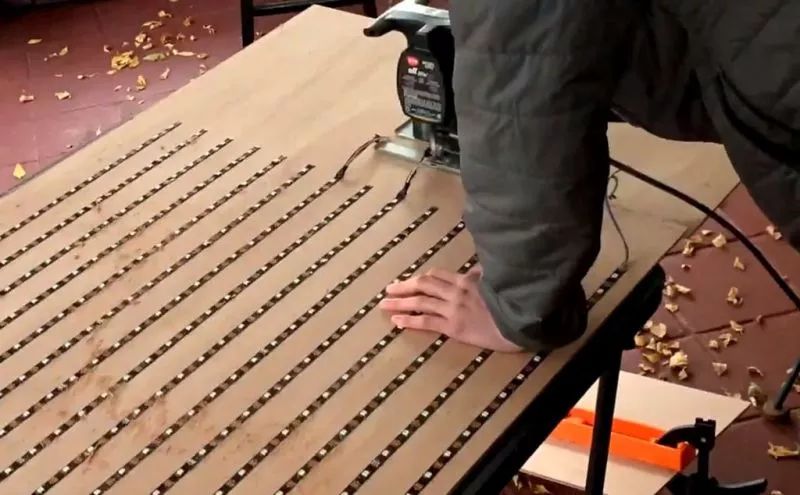
Since the wooden board I bought is four inches, but I found out that only three inches are needed, so I need to saw off the excess material.However, if you want to make a larger display wall, just add more 3.6-inch wall blocks.
Making the Button Matrix
This part is not only time-consuming but also requires patience.In this part, we will use the keyboard library included in the Arduino IDE to connect 64 buttons in rows and columns.The example shown is a 4×4 grid, and you can increase it to an 8×8 grid or choose your own matrix size.
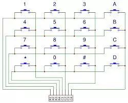
1. Prepare sixteen wires, each 3.6 inches long and stripped at the ends, for button installation in the center of each wall block.
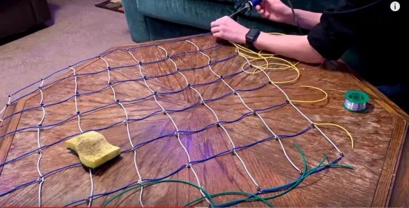
2. Solder one leg of each tactile switch to the row (horizontal) wire.Solder the column (vertical) wire to the diagonal of the row wire.When the tactile switch is pressed, it will connect the horizontal and vertical wires together.
3. Each row and each column needs a wire connected to the digital pins of the Arduino.Color code each wire for easier troubleshooting; during the check, I also changed several pins.
4. Glue all buttons to the wooden board.Ensure that each button is securely fixed.
Testing the Circuit
Once all the LED strips and buttons are installed, you can start testing.In the code, there are functions to test the LED strips and buttons.If there are any issues, you can detect and resolve them promptly.Note to troubleshoot as much as possible before adding the wall blocks.
Installing the 3D Wall
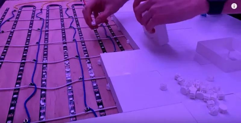
1. To connect the blocks to the wooden board, a 3D printed bracket is designed to secure the four adjacent blocks at each corner together.Glue one block at a time, and slowly connect them together, keeping them tightly packed without leaving extra space.
2. Additionally, print 64 spacers and glue them onto the plunger of each block.These spacers can compensate for the height added by the bracket and provide space for the plunger click, compensating for the slight gaps between buttons.
The STL files for the bracket and spacers can be downloaded from the project file library:https://make.quwj.com/project/192
Programming
So far, the hardware part is complete, and it’s time to start programming!Currently, programmed patterns include rainbow patterns and click painting modes.You can see the specific effects in the video.
Download the code from the project file library:https://make.quwj.com/project/192Additionally, you can dynamically display custom visual effects by modifying the code.
Future Possible Features
1. Audio visualizer using a microphone and FFT Arduino library.2. Designable games (checkers, tic-tac-toe, battleship, go).3. Memory function.4. More playable games on the grid.
Project file library address:
http://make.quwj.com/project/192
via instructables.com/id/Interactive-LED-Tile-Wall-Easier-Than-It-Looks/
Click the link at the end of the article to read the original text
Creating Colorful LED Balls with ESP32
3D Printed OLED Screen Indoor Thermometer
BrachioGraph: Raspberry Pi Drawing Machine
Fun Endless 2019 Annual Popular Project Review
Modifying NumWorks Calculator with Raspberry Pi
Deep Learning:Owl “Zombie” Detector
Creating Electric Wheelchair Rearview Mirror with Raspberry Pi Zero
Raspberry Pi DIY Real-Life CS Gear:Infrared Laser Gun


