Abstract: We come across many operating systems in our daily lives, such as Windows, Android, iOS, and Linux. Microcontrollers also have their own operating system, called Real-Time Operating System (RTOS). So, what are the differences between these real-time operating systems and the ones we commonly use?
The operating systems we frequently use are actually non-real-time operating systems. The reason they are called non-real-time is that their kernel uses a time-slicing scheduling method for tasks. For example, if there are three tasks: Task A, Task B, and Task C, the time-slicing mechanism will let Task A run for a while, then switch to Task B, then to Task C, and continue this cycle.
What is the downside of this? If in an autonomous vehicle, Task C is responsible for detecting and avoiding obstacles, and if Task C does not get executed in time, it could lead to the vehicle colliding with an obstacle, which is very dangerous. Therefore, real-time operating systems support preemptive scheduling mechanisms. This means we can increase the priority of Task C. When Task C is ready, it will run first, ensuring its real-time performance. The fundamental function of an operating system is to implement task scheduling.
Next, let’s understand FreeRTOS, the task scheduling of real-time operating systems. Before understanding real-time operating systems, we need to understand the kernel, using the ARM Cortex-M3 kernel as a template. First, let’s look at the CPU registers, which is a table of the CM3 CPU registers. CM3 has general-purpose registers R0-R15 and some special function registers. R0-R12 are the most “general-purpose”, but the vast majority of 16-bit instructions can only use R0-R7 (low group registers), while 32-bit Thumb-2 instructions can access all general-purpose registers. Special function registers have predefined functions and must be accessed through specific instructions.
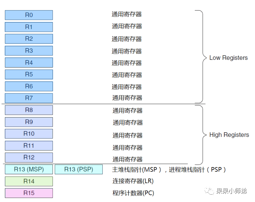
As we can see, the previous registers are all general-purpose. They are divided into low registers (which all instructions can access) and high registers (which can only be accessed by a few 16-bit Thumb instructions). Why are they divided this way? In fact, in earlier versions of the ARM core, the ARM instructions and Thumb instructions could access different registers, hence the division into low and high registers. Additionally, R13, R14, and R15 are the stack pointer, link register, and program counter register, respectively.
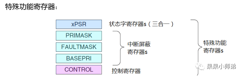
Moreover, CM3 has some special registers.
Have you ever thought about how the CPU enters an interrupt? It essentially interrupts the previous task. How does the CPU return to the original task after executing the interrupt and ensure that the original task does not lose data?
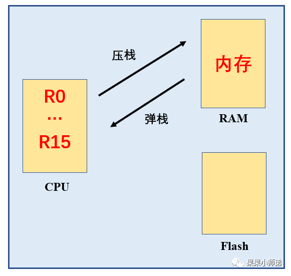
Before entering the interrupt, which is on the left side, we first store the values in the CPU registers into memory, also known as pushing onto the stack. Then we run the interrupt service function, during which the CPU registers will be modified. However, this does not matter because after the interrupt ends, when returning to the original task, the previous values of the CPU registers will be retrieved from memory, also known as popping from the stack. This mechanism ensures that the original process’s data is not lost.
Next, let’s understand the stack-push order of CM3.
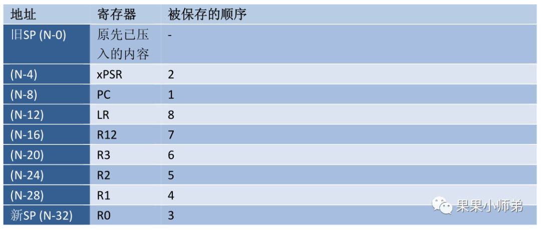
The above diagram shows the hardware stack-push order when Cortex-M3 enters an interrupt. This means that when it enters an interrupt, the hardware automatically pushes these several registers onto the stack: the PC pointer, the xPSR special register, general-purpose registers R0 to R3, general-purpose register R12, and the LR link register (which saves the return address of the function) will be pushed onto the stack in the order shown in the third column.

After successfully pushing onto the stack, when the interrupt completes and returns to the original process, the contents of the stack will be popped into the CPU registers; the popping order is exactly the reverse of the pushing order. That is, LR is popped first, and then popped in order downwards, because the stack is last in, first out, so this is the popping order.
Previously, we learned that the CPU has R0-R15 and several special registers. When the interrupt function arrives, the above registers are automatically pushed onto the stack by hardware, but there are also a few that are pushed onto the stack by software. How should we understand this?
For example:
When the program is executing:
if(a<=b)
 a=b;
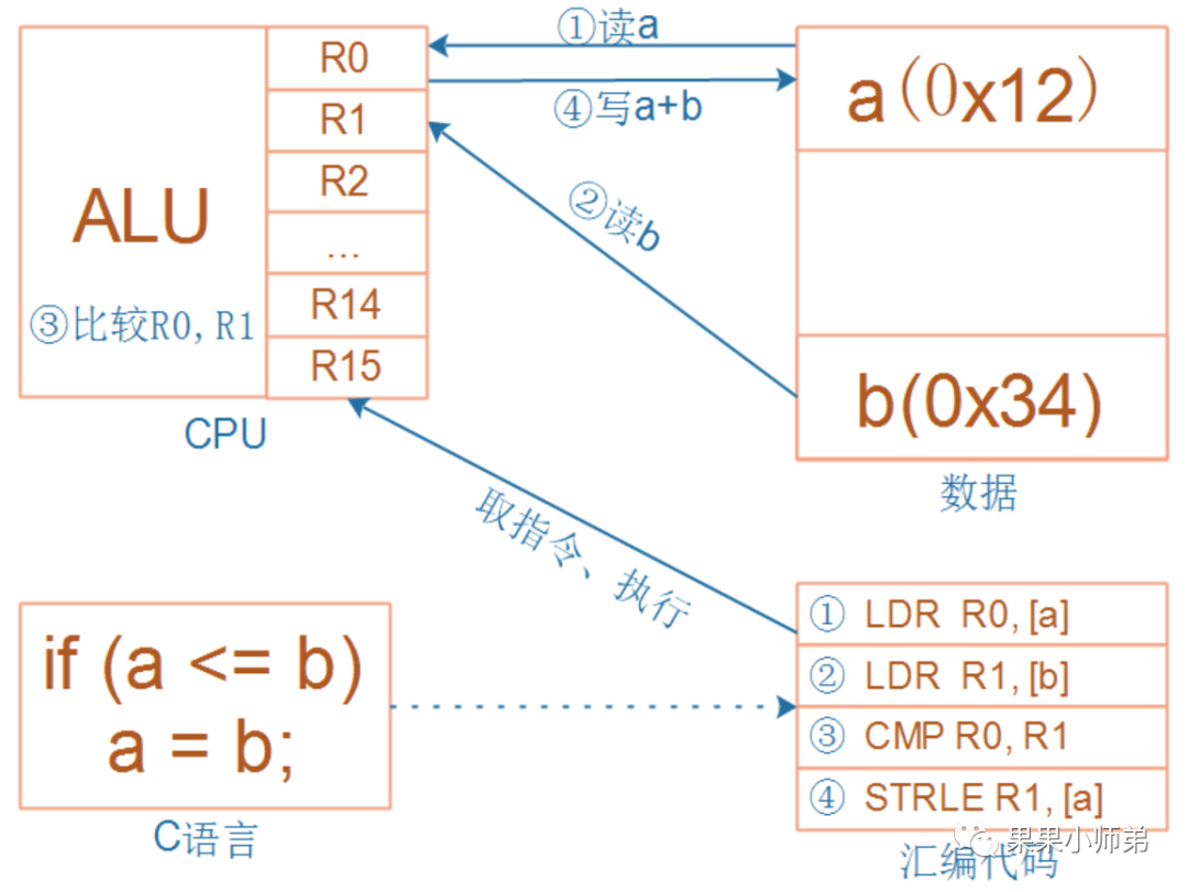
At this moment, an interrupt suddenly occurs. Any program will eventually be converted into machine code, and the above C code can be converted into the assembly instructions on the right.
For these four instructions, they can be interrupted at any time; how can we ensure that the program can run correctly after the exception is handled?
These four instructions involve registers R0 and R1; when the program is interrupted and resumes execution, R0 and R1 must remain unchanged. When the third instruction is executed, the comparison result is saved in the program status register PSR; when the program is interrupted and resumes execution, the program status register must remain unchanged. These four instructions read memory a and b; when the program is interrupted and resumes execution, memory a and b must remain unchanged. It is easy to maintain memory unchanged as long as the program does not go out of bounds. Therefore, the key is to ensure that R0, R1, and the program status register remain unchanged (of course, not just these registers):
-
Before handling the exception, save these registers onto the stack, which is called saving the context, or pushing onto the stack. -
After handling the exception, restore these registers from the stack, which is called restoring the context, or popping from the stack.
Let’s take another example:
void A()
{
    B();
}
For instance, when function A calls function B, function A should know: R0-R3 are used to pass parameters to function B; function B can modify R0-R3 at will; function A should not expect function B to save R0-R3; saving R0-R3 is the responsibility of function A; the same goes for LR and PSR, saving them is the responsibility of function A. This is done by hardware.
For function B: if I use any of R4-R11, I will save them at the entry of the function and restore them from the stack before returning to ensure that R4-R11 remain unchanged from the perspective of function A before and after calling function B.
Assuming function B is the exception/interrupt handler, if function B can guarantee that R4-R11 remain unchanged, then during the context saving, the hardware only needs to save registers R0-R3, R12, LR, PSR, and PC, which are these eight registers.
Next, let’s understand the two special interrupt mechanisms of CM3. When CM3 starts responding to an interrupt, three hidden streams surge within it:
-
Pushing onto the stack: pushing the values of eight registers onto the stack. -
Fetching the vector: finding the corresponding service program entry address from the vector table. -
Selecting the stack pointer MSP/PSP: updating the stack pointer SP, updating the link register LR, and updating the program counter PC.
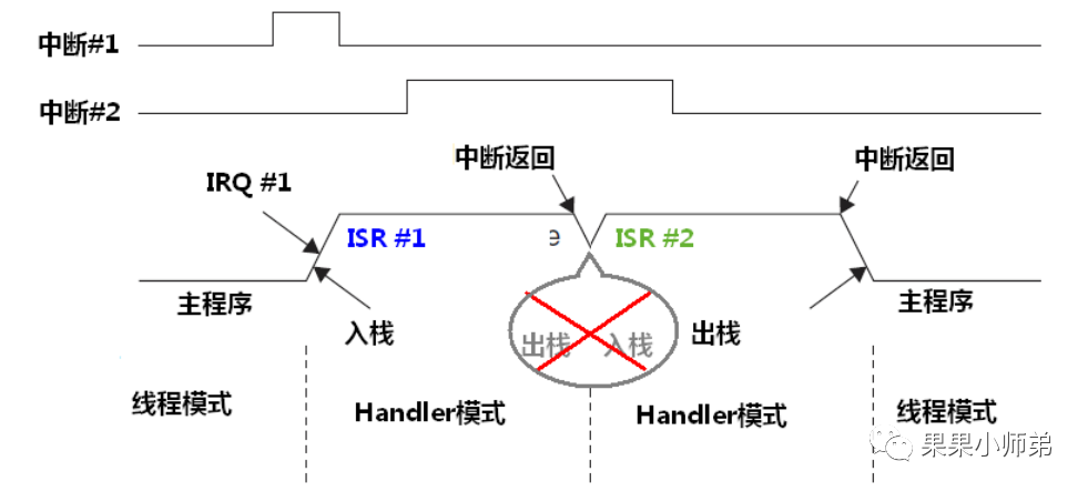
The first is called tail-chaining interrupt
We know that when entering an interrupt, it needs to execute the stack-push operation, and when exiting the interrupt, it needs to execute the stack-pop operation. When two interrupts occur, after the first interrupt completes, the second interrupt needs to be executed. In the CM3 processor core, it will not execute the stack-pop and stack-push operations again. This means that the time for stack-pop and stack-push is saved, essentially allowing the second interrupt to ‘bite off’ the tail of the first interrupt. It does not allow it to pop the stack again, hence it is called a tail-chaining interrupt.
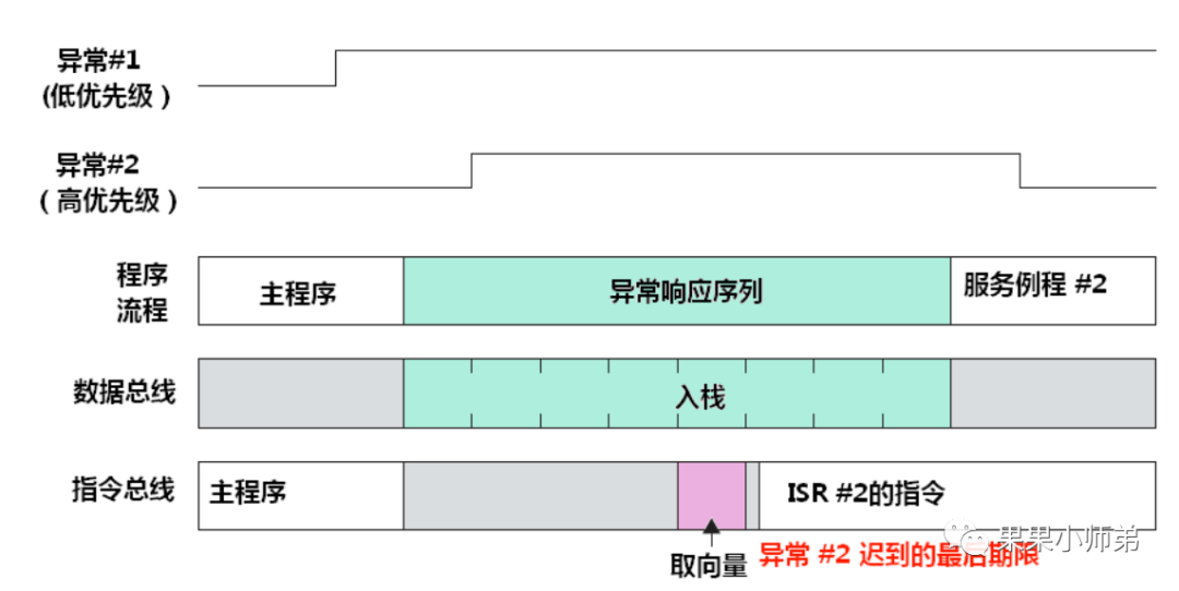
The second interrupt mechanism is called late interrupt
Late interrupt means that when a high-priority task arrives, if the previous low-priority task’s fetching the vector has not been completed (the previous low-priority task has not yet found the corresponding service program entry address from the vector table), then this stack-push operation is done for the high-priority task. This means that even if the high-priority interrupt arrives late, it can still use the stack pushed by the low-priority interrupt.
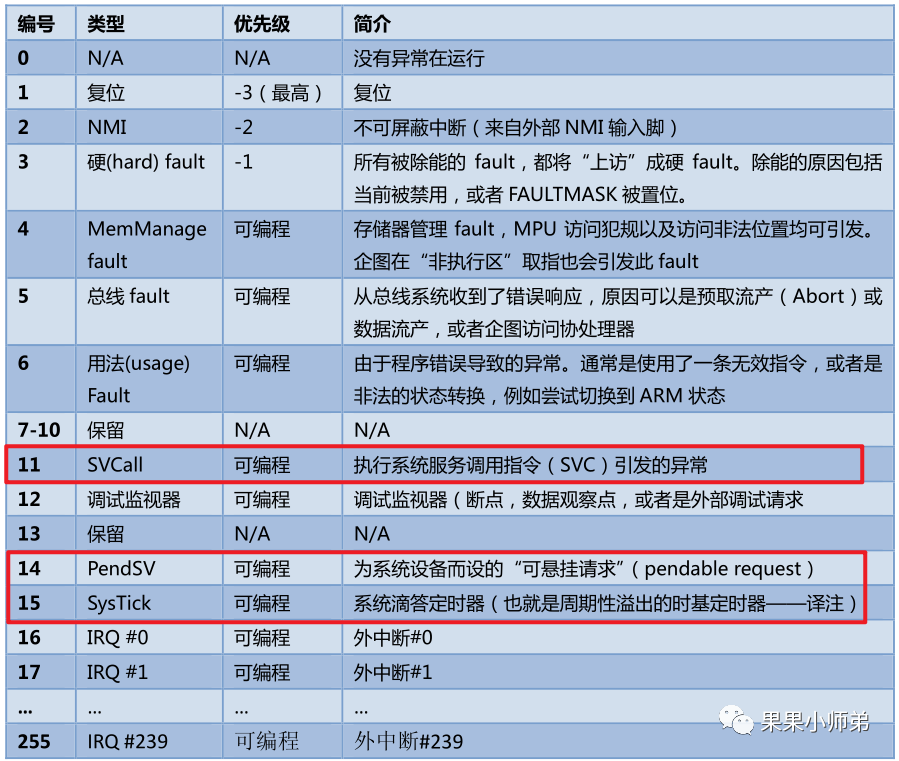
The interrupt table of CM3 processor core
In real-time operating systems, the three interrupts frequently used are PendSV, Systick, and SVC.

In FreeRTOS, the Systick interrupt is used to provide the clock cycles for the real-time operating system. The PendSV is a pending interrupt used for switching processes. The SVC in FreeRTOS is only used once, which is when the first process is started.
__asm void vPortSVCHandler( void )
{
/* *INDENT-OFF* */
    PRESERVE8

    ldr r3, = pxCurrentTCB   // Get the current task control block
    ldr r1, [ r3 ] // Use pxCurrentTCBConst to get the pxCurrentTCB address
    ldr r0, [ r1 ] // The first item in pxCurrentTCB is the stack top task
    ldmia r0 !, { r4 - r11 } // Manually push R4-R11, R14 registers onto the stack
    msr psp, r0    // Restore the task stack pointer
    isb
    mov r0, # 0
    msr basepri, r0 // Enable all interrupts
    orr r14, # 0xd
    bx r14
/* *INDENT-ON* */
}
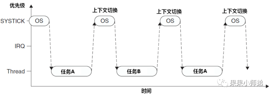
At this point, some may ask, why not switch tasks directly in the Systick interrupt instead of in PendSV? We can look at the following:
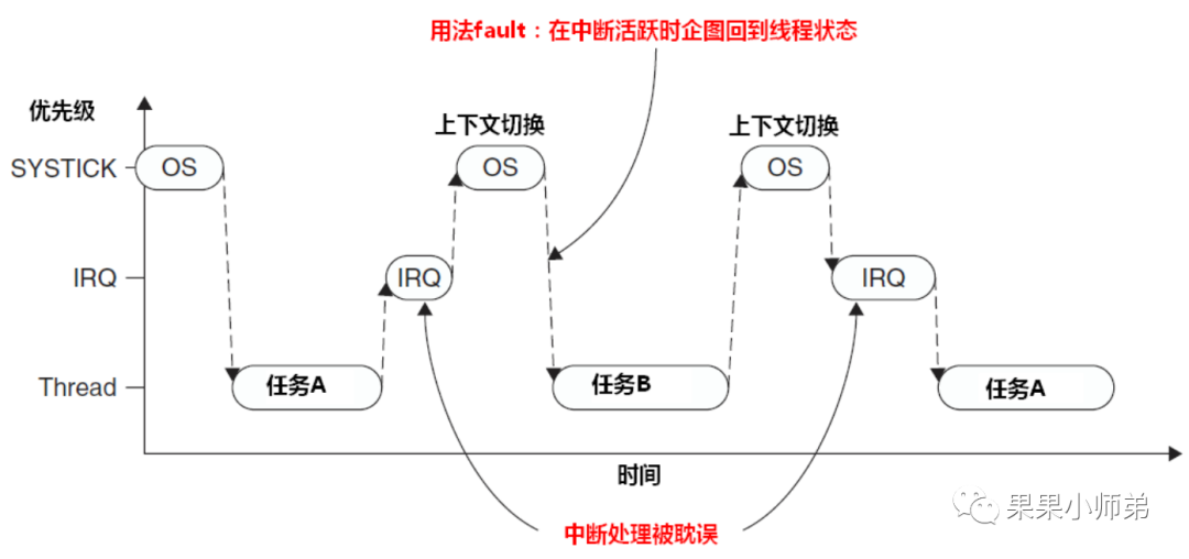
If the Systick interrupt occurs while a previous interrupt is being executed, that is, if an IRQ is being executed, it will be interrupted, and the Systick will execute the context switch. At this point, it switches to task B, which must wait for a while until the next context switch to return to the original IRQ that is executing. This way, the interrupt cannot be completed, and it can be seen that the interrupt is severely delayed. Therefore, this is not convenient and prone to errors.
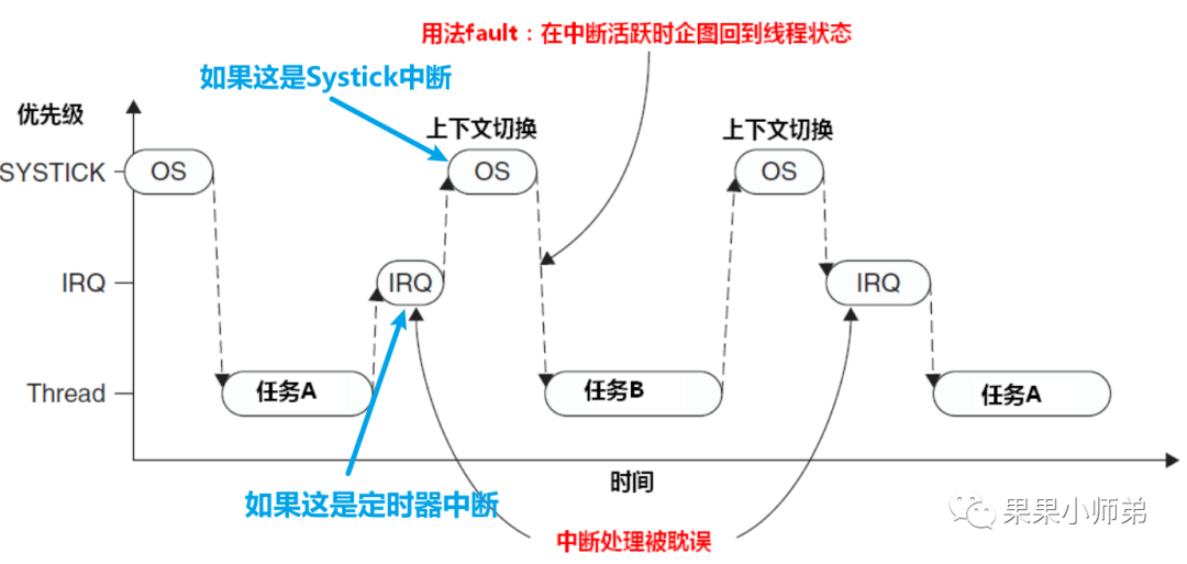
They came up with a solution: I will check in the Systick if there is an interrupt currently executing; if there is, we will not switch; if there is not, we will switch. However, this can also cause a problem: if the interrupt time of this interrupt function is similar to that of Systick, for example, if this is a timer interrupt, this is the Systick system clock interrupt. Their interrupt cycles are both 1 millisecond; they often face the situation where both arrive simultaneously. This can lead to delays in process switching, so this is not ideal either.
Thus, the PendSV pending interrupt was introduced
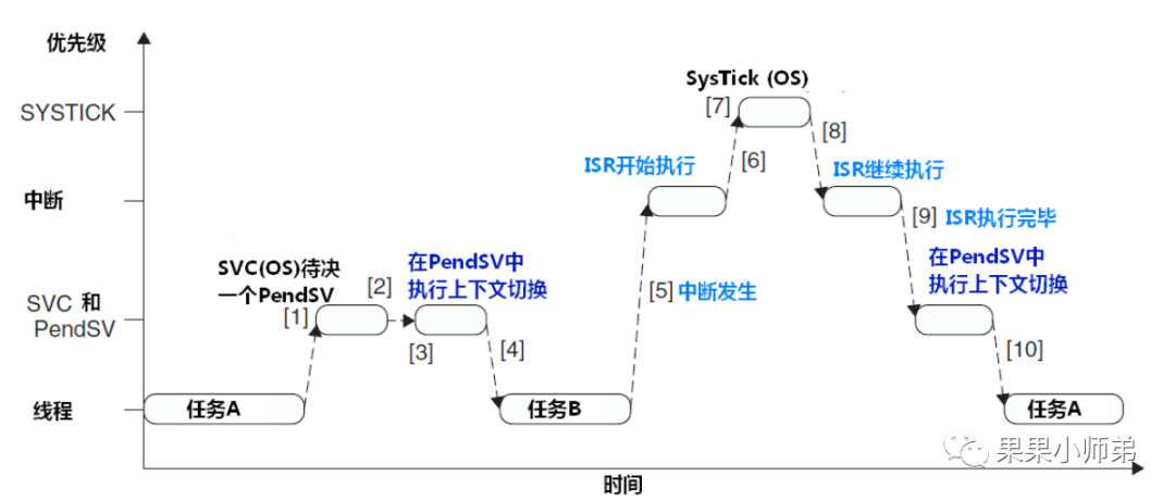
What are the benefits of this interrupt? We can see that in Systick, it only sets the PendSV interrupt bit pending, meaning it does not execute the frequently switching operation. Instead, it waits until all interrupts have been processed, then executes the context switch in PendSV. This ensures timely task switching and timely execution of interrupts. The PendSV exception will automatically delay the request for context switching until all other ISR have completed processing before releasing it. To implement this mechanism, PendSV needs to be programmed as the lowest priority exception. If the OS detects that some IRQ is active and has been preempted by Systick, it will suspend a PendSV exception to delay the execution of the context switch.
So, how is the process switch performed in PendSV? Here, it is written in assembly language.
__asm void xPortPendSVHandler( void )
{
    extern uxCriticalNesting;
    extern pxCurrentTCB;
    extern vTaskSwitchContext;

    PRESERVE8

    mrs r0, psp// Save the current process stack pointer in R0
    isb

    ldr r3, =pxCurrentTCB // Get the current task control block
    ldr r2, [ r3 ] // Save the task control block address in R2

    stmdb r0 !, { r4 - r11 } // Manually push R4-R11, R14 registers onto the stack
    str r0, [ r2 ] // Write the current stack top address into the control block

    stmdb sp !, { r3, r14 }
    mov r0, #configMAX_SYSCALL_INTERRUPT_PRIORITY// Write the immediate value represented by this macro into R0, which is the highest priority interrupt the user wants to mask
    msr basepri, r0 // Write the value of R0 register into the special basepriority register, which can finely control interrupts, masking interrupts below this priority while allowing interrupts above this priority
    dsb
    isb
    bl vTaskSwitchContext
    mov r0, #0
    msr basepri, r0 // Cancel interrupt masking
    ldmia sp !, { r3, r14 } // Restore the current stack pointer from R3 register, where R3 stores the value just fetched from the next task control block

    ldr r1, [ r3 ]
    ldr r0, [ r1 ] // Save the new task's stack top into R0 register
    ldmia r0 !, { r4 - r11 } // Manually pop R4-R11 and R14 registers from the stack
    msr psp, r0
    isb
    bx r14  // Return from the exception, after which hardware will automatically restore the other registers and use the process stack pointer.
    nop
/* *INDENT-ON* */
}
Now we have learned about the basic function of task switching in the FreeRTOS real-time operating system. However, to create a complete real-time operating system, many other elements are required, such as lists and list items, task notifications, low-power mode task control blocks, memory management for stack handling, idle tasks, semaphores, software timers, event flag groups, and so on.
Reference materials:
"Detailed Explanation of FreeRTOS Source Code and Application Development"
"Authoritative Guide to ARM Cortex-M3"
Let’s see how interrupts are implemented in the program
The following table is from “Authoritative Guide to ARM Cortex-M3”:
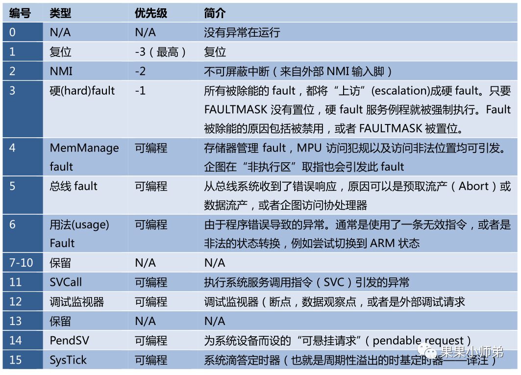
In Cortex-M3, there are 15 exception interrupts, corresponding to the following diagram in STM32:
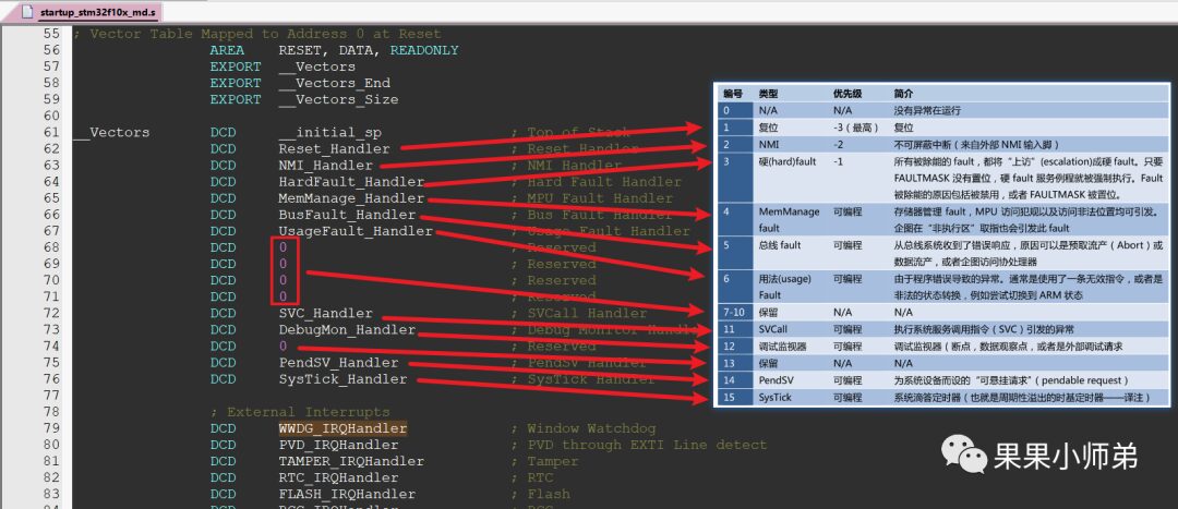
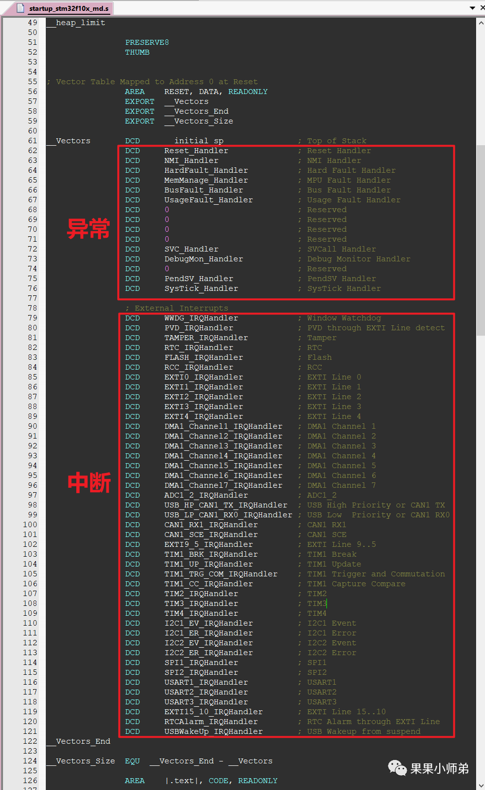
In the startup file, there are not only exceptions but also interrupts; in fact, interrupts are a type of exception. When we talk about interrupts, we often refer to signals sent by certain devices, such as the GPIO module sending a signal to the CPU when the I2C controller finishes sending data, or the UART generating an interrupt after receiving data. Note that interrupts are a type of exception. Other exceptions generally include: reset is also an exception, various errors also belong to exceptions.
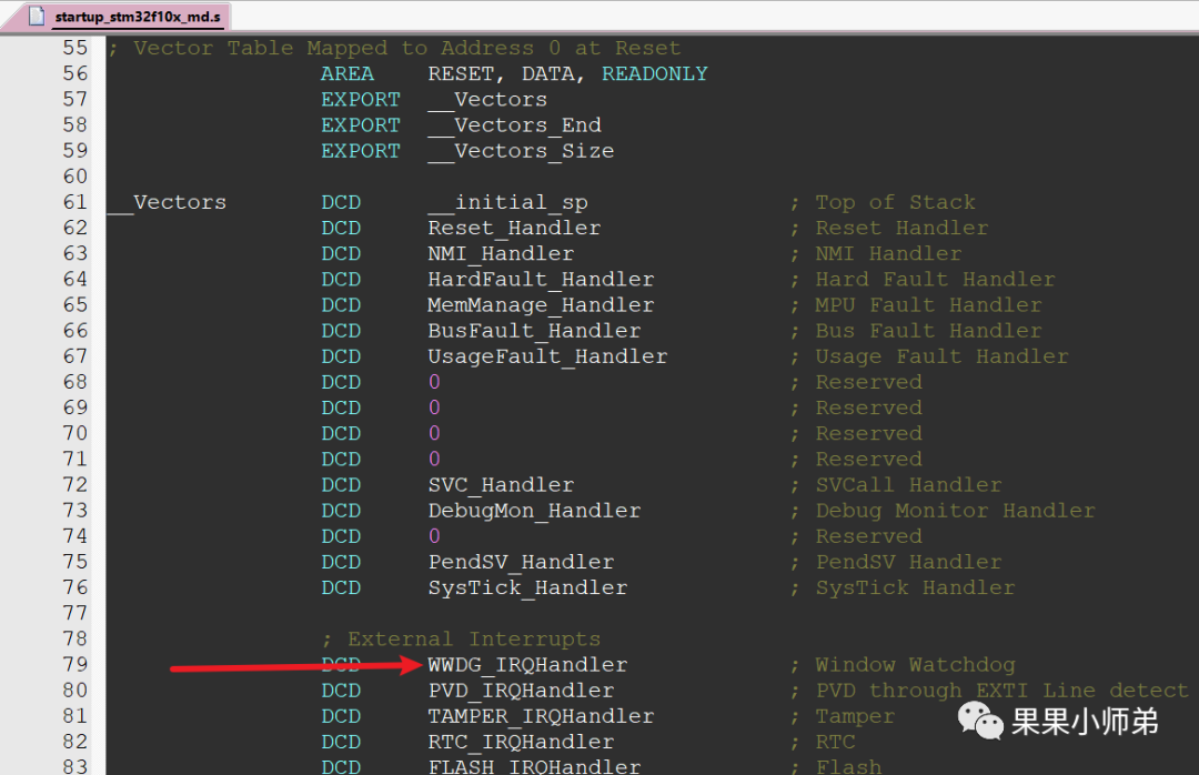
When our board is reset, the CPU executes the Reset_Handler function in the interrupt vector table.
When our board’s watchdog interrupt occurs, the CPU executes the WWDG_IRQHandler function in the interrupt vector table.
You might have a question: How does the CPU know which function to jump to in the interrupt vector table?
This is determined by hardware because software has not started executing at this point; hardware determines which exception or interrupt has occurred, and when recovering, it is triggered by software and restored by hardware.
/**
  * @brief  This function handles NMI exception.
  * @param  None
  * @retval None
  */
void NMI_Handler(void)
{
}

/**
  * @brief  This function handles Hard Fault exception.
  * @param  None
  * @retval None
  */
void HardFault_Handler(void)
{
  /* Go to infinite loop when Hard Fault exception occurs */
  while (1)
  {
  }
}

/**
  * @brief  This function handles Memory Manage exception.
  * @param  None
  * @retval None
  */
void MemManage_Handler(void)
{
  /* Go to infinite loop when Memory Manage exception occurs */
  while (1)
  {
  }
}

/**
  * @brief  This function handles Bus Fault exception.
  * @param  None
  * @retval None
  */
void BusFault_Handler(void)
{
  /* Go to infinite loop when Bus Fault exception occurs */
  while (1)
  {
  }
}

/**
  * @brief  This function handles Usage Fault exception.
  * @param  None
  * @retval None
  */
void UsageFault_Handler(void)
{
  /* Go to infinite loop when Usage Fault exception occurs */
  while (1)
  {
  }
}

/**
  * @brief  This function handles SVCall exception.
  * @param  None
  * @retval None
  */
void SVC_Handler(void)
{
}

/**
  * @brief  This function handles Debug Monitor exception.
  * @param  None
  * @retval None
  */
void DebugMon_Handler(void)
{
}

/**
  * @brief  This function handles PendSVC exception.
  * @param  None
  * @retval None
  */
void PendSV_Handler(void)
{
}

/**
  * @brief  This function handles SysTick Handler.
  * @param  None
  * @retval None
  */
void SysTick_Handler(void)
{
}
Alright, now you understand the interrupt flow of the MCU and the basic principles of RTOS, right?
Source: Guoguo Xiaoshidi
Due to recent changes in the WeChat public platform push rules, many readers have reported not being able to see updated articles in time. According to the latest rules, it is recommended to click on “Recommended Reading, Share, Collect, etc.” more often to become a regular reader.
Recommended Reading:
-
“Chip Olympics” paper included, China ranks first in the world
-
All employees dismissed! Another electronic giant in Shenzhen announces shutdown
-
A Tesla suspected of spontaneous combustion in Shanghai, causing 12 luxury cars including Rolls Royce to be burned, with losses up to 50 million yuan!
Please click 【View】 to give the editor a thumbs up
