1. Required Materials
-
Two old CD drives
-
One Arduino UNO development board
-
Two A4988 stepper motor driver modules
-
One 12V2A power supply module
-
One 250mW laser head
-
One acrylic board
-
Several wires
-
Several screws
-
AB glue
2. Disassemble the CD Drive
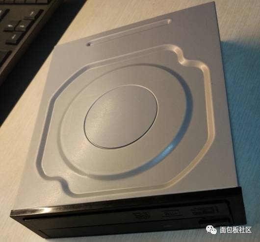
Since I finished the mini laser engraver almost half a month ago, some pictures were not taken at that time, so some images here are sourced from the internet.
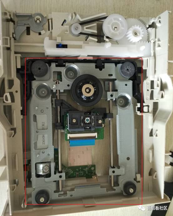
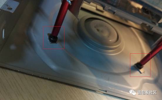
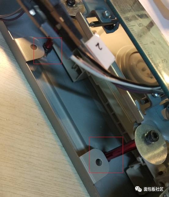
Note: Do not throw away the remaining materials after disassembly. For example, the strong magnets on both sides of the laser head, the CD drive casing, and plastic screws, etc.
The red box in the image shows the position of the strong magnets.
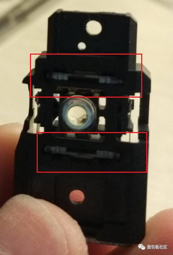
3. Connect the Motor Pins
Note: The order of the motor pins is random.
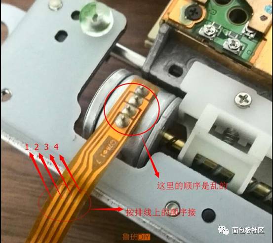
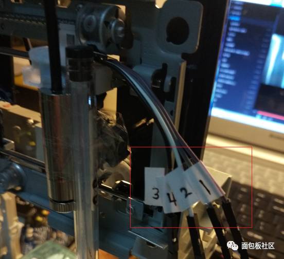
It’s best to mark the pin order (as indicated by the red box in the image).
4. Secure the Acrylic Board and Add Supports to the X-Axis CD Drive
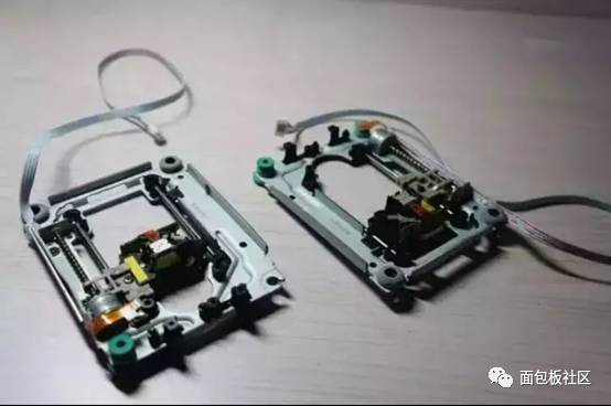
The lower CD drive I define as the x axis, while the upper one is the y axis.
Here, I cut the plastic in the x axis CD drive to make it flat and use AB glue to stick the acrylic board on.
Add four support pillars to the x axis, with each pillar secured with a screw.
At this point, the x axis CD drive can be set aside.
5. Secure the Y-Axis CD Drive and Bracket
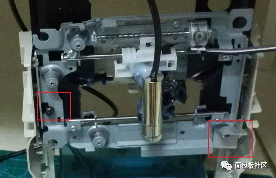
First, fix the laser head onto the y axis CD drive, and once the glue is dry, fix the CD drive onto the black plastic. When adding screws here (the space is very limited, so I only added two screws; if you have spacers, try to add them. I have limited materials and could only take a small piece of spacer from the corner), some areas of the white plastic may block the vertical movement of the CD drive, so you may need to use force to remove the obstacles. The reason for fixing it on the black plastic is that it utilizes materials from the old CD drive; also, the black plastic has a motor behind it that allows the y axis CD drive to move up and down freely, making it easier to adjust the focus. This also allows for future modifications (for example, turning the motor behind into a z axis for 3D engraving or printing ^_^). Additionally, the materials from the CD drive are already structured vertically and horizontally, making it more stable than a self-made frame.
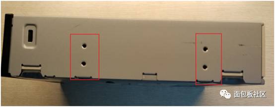
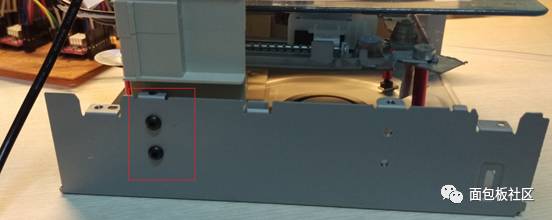
At this point, the y axis CD drive, black plastic, and white plastic are integrated. Drill two holes below both sides of the white plastic, roughly the same size as the holes on the CD drive’s metal casing, and then secure with screws. At this point, the entire assembly is very stable.
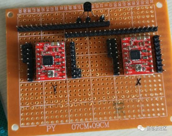
6. Assemble the XY Axis CD Drives

Twist the screws under the x axis CD drive to adjust the acrylic board to a level position.
Then place the x axis CD drive under the y axis CD drive, adjust the position, and place the strong magnets under the four pillars. Do not underestimate these four strong magnets; their attraction is enough that you cannot pull out the x axis CD drive with one hand. So it’s best to fix the position correctly the first time.
At this point, you may realize that old CD drives are full of treasures.^_^
7. Connect According to the Circuit Diagram
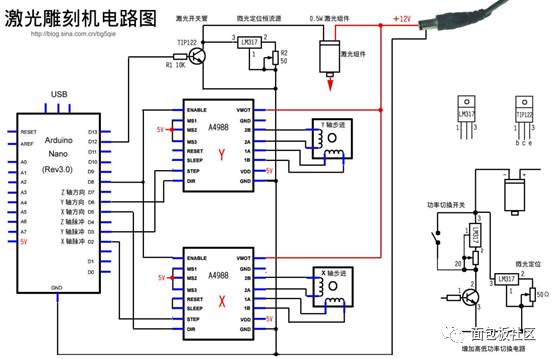
This diagram was sourced from the internet.
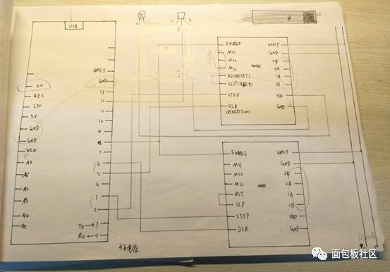
This one I drew myself. Since I am not an electronics major, it’s purely amateur, so the circuit diagrams are all hand-drawn.
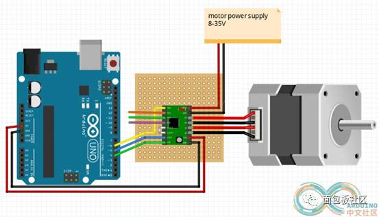
This is the connection method for the A4988, and there are also diagrams for using the A3967.
8. Power Supply Issues
Some experts may think power supply is not an issue, but as an amateur, I encountered some problems with the power supply, and I want to share this with everyone.
First, the motor requires a 12V2A power supply, while the Arduino UNO development board and A4988 require 5V for operation.
5V power is easy to find; for example, a mobile phone charger can output 5V.
I borrowed a 12V power supply from a friend who plays with flying devices, which happens to output 12V2A.
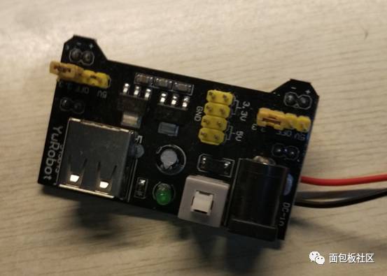
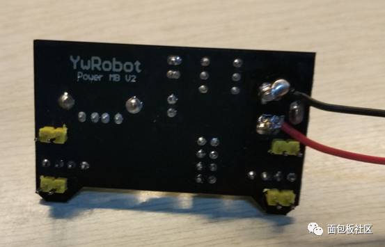
Modify the power supply module by inserting the 12V charger into the power supply module, measure the positive and negative, and lead the wires out for use! It’s very convenient; this way, both 5V and 12V power are in one module.
This is what it looks like after connecting.
9. Software Installation
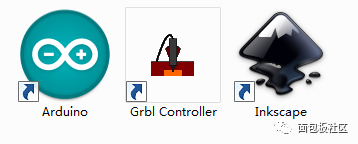
① Download GRBL Controller , which is the control software for the laser engraver.
② Download INKSCAPE , a vector graphics software that can convert to Gcode files.
③ Download GRBL firmware and upload it to the Arduino .
The first software icon is for Arduino programming.
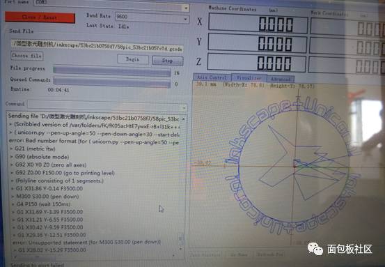
This is a G code I found online.
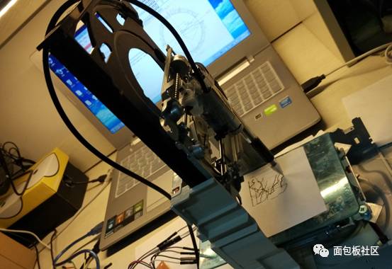
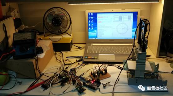
10. Debugging
First connect the Arduino , and after downloading the code, turn on the power.
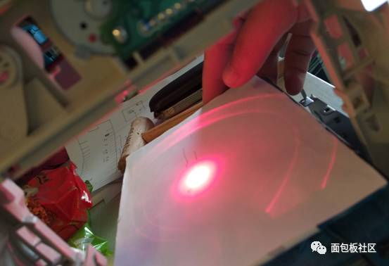
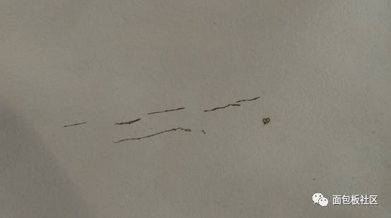
Here, I didn’t adjust the focus well, so I could only drag the cardboard to burn a few thin lines and a small hole. Later, I directly used a pen instead of the laser.
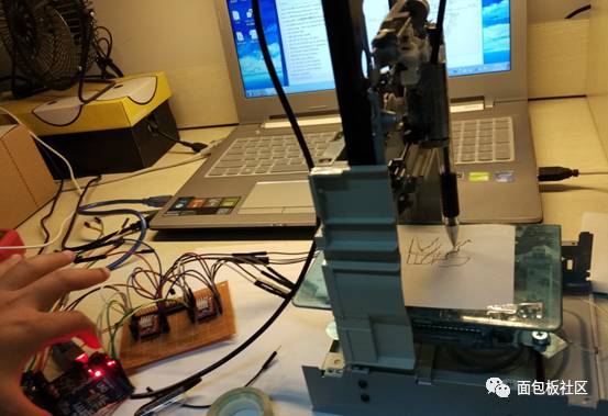
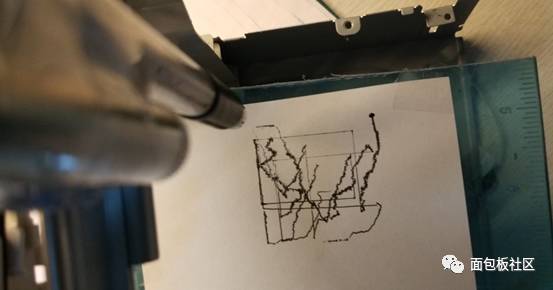
Since the G code found online had a drawing range larger than what the mini laser could handle, I had to drag it back when it reached the boundary, and the final drawing was also quite poor. This project still has a lot of room for improvement; I share it hoping to help those who want to try it.
Finally, I hope everyone uses tools with caution.