
With the rapid development of modern ship technology, the operation of ME electronic fuel injection engines has become increasingly stable, and new ships are increasingly adopting ME electronic fuel injection engines. Compared to the traditional MC engines, the ME electronic fuel injection engines have made significant changes in pneumatic remote control. The pneumatic control system of the MC traditional engine has more than 30 pneumatic and solenoid valves, while the pneumatic control system of the ME electronic fuel injection engine has fewer than 10 (as shown in Figure 1). This design reduces the likelihood of failure of pneumatic and solenoid valves, significantly simplifies the large and complex pneumatic control system, and allows for quicker and easier fault diagnosis and maintenance when the pneumatic control system fails.
MAN B&W ME Electronic Fuel Injection Engine Pneumatic Control System Diagram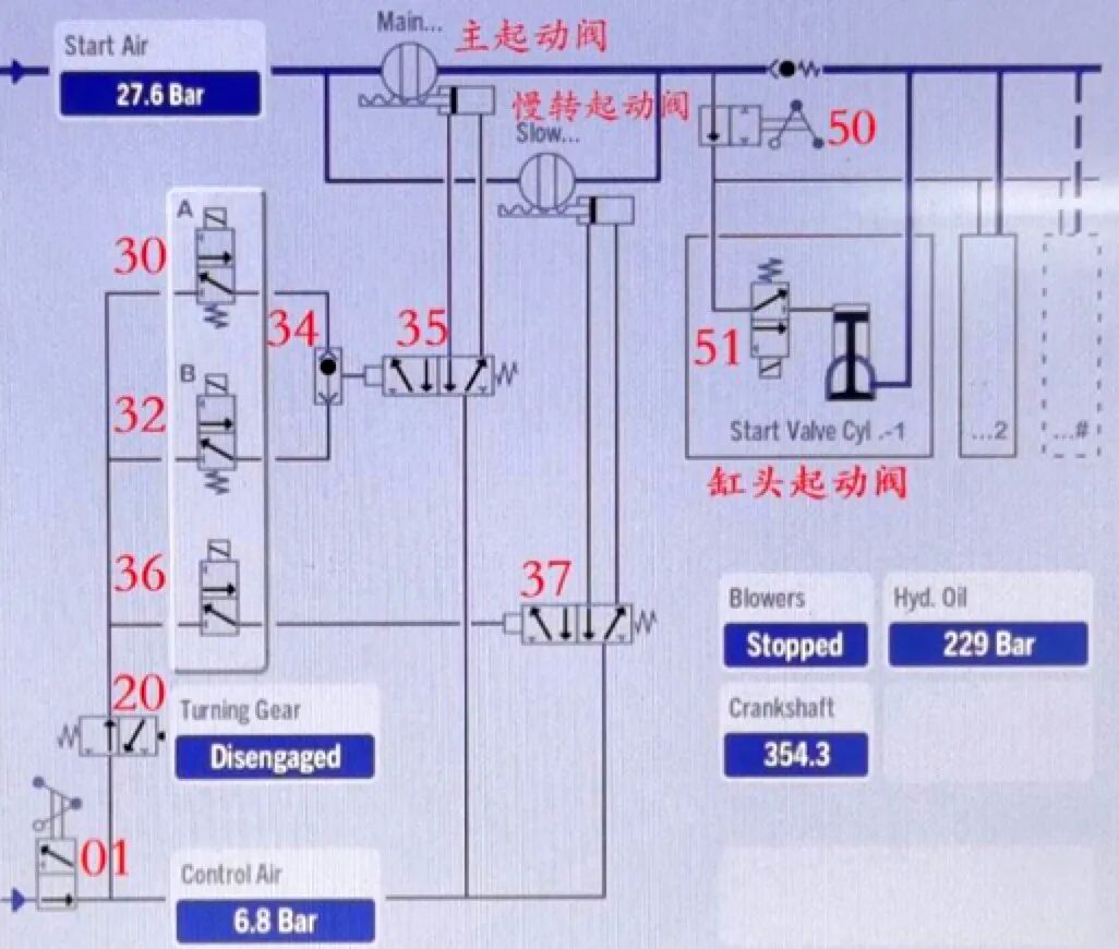
Figure 1 MAN B&W ME Electronic Fuel Injection Engine Pneumatic Control System Diagram
1. Valve Component Description
Valve 01: Ball valve, manual cut-off for 7bar control air.
Valve 20: Two-position three-way valve, starting interlock when the turning machine engages.
Valve 30: Two-position three-way solenoid valve, sends 7bar pilot air to valve 35, enabling the opening or closing of the main starting valve.
Valve 32: Functions identically to valve 30.
Valve 34: Bidirectional shut-off valve.
Valve 35: Two-position five-way pneumatic valve, controls the opening or closing of the main starting valve.
Valve 36: Two-position three-way solenoid valve, sends 7bar pilot air to valve 37, enabling the opening or closing of the slow-turn starting valve.
Valve 37: Two-position five-way pneumatic valve, controls the opening or closing of the slow-turn starting valve.
Valve 50: Ball valve, manual cut-off for 30bar compressed air to valve 51.
Valve 51: Two-position three-way solenoid valve, prevents 30bar compressed air from entering the cylinder head starting valve when the main starting valve is leaking. When the main engine needs to start, it allows 30bar starting air to pass through and opens the cylinder head starting valve. Each cylinder has one solenoid valve 51.
2. Solenoid Valve Control Description
(1) Control unit description: MOP-A, MOP-B, Main Operating Panel. EICU-A, EICU-B, Engine Interface Control Unit. ECU-A, ECU-B: Engine Control Unit. CCU: Cylinder Control Unit, each cylinder has one CCU.
(2) Solenoid valve 30 is controlled by ECU-A, and solenoid valve 32 is controlled by ECU-B. When the main engine has forward or reverse commands, both will be powered simultaneously to ensure a successful engine start; they lose power after starting and parking.
(3) Solenoid valve 36 for slow turning is controlled by ECU-A; it is powered when the main engine has a slow-turn signal; it loses power when there is no slow-turn signal and during parking.
(4) Each cylinder’s solenoid valve 51 is controlled separately by each cylinder’s CCU. Based on the forward or reverse command, the CCU outputs a signal to power the corresponding cylinder’s solenoid valve 51, allowing the cylinder head starting valve to open and enabling the main engine to rotate.
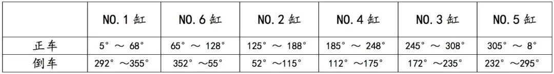
3. Crankshaft Angle Description for Powering Solenoid Valve 51 of Each Cylinder
Taking a six-cylinder ME engine as an example, the firing order is 162435, and the crankshaft angle between two adjacent firing cylinders in a two-stroke engine is 360°/number of cylinders, which is 60°. The crankshaft angle detected by the crankshaft encoder of the ME engine, with the crankshaft angle at 0° when cylinder NO.1 is at the top dead center, is the starting point. The crankshaft angles for the other cylinders at their top dead centers are NO.6 cylinder at 60°, NO.2 cylinder at 120°, NO.4 cylinder at 180°, NO.3 cylinder at 240°, and NO.5 cylinder at 300°. During the starting of the main engine in the forward and reverse directions, the crankshaft angles at which solenoid valve 51 is powered and the cylinder head starting valve is opened are 5° to 68° after top dead center and 5° to 68° before top dead center, as detailed in Table 1.
Table 1 Crankshaft Angles When Solenoid Valve 51 of Each Cylinder is Powered
4. Main Engine Starting Control Description
The control command for forward or reverse is issued from the bridge or central control room, processed by the EICU, and sent to the ECU. The ECU powers solenoid valves 30 and 32 simultaneously, working in the upper position. The 7bar control air passes through solenoid valves 30 and 32 to valve 34, providing pilot air to valve 35, which works in the left position. At this point, the 7bar control air enters the left side of the main starting valve cylinder through valve 35, opening the main starting valve. Simultaneously, the air on the right side of the main starting valve cylinder is released through valve 35’s left position. This allows the 30bar starting air to enter in front of each cylinder’s solenoid valve 51 and the cylinder head starting valve, waiting to be activated. According to the forward or reverse command, the corresponding cylinder’s CCU outputs a signal to power the corresponding cylinder’s solenoid valve 51, allowing the 30bar starting air to first open the cylinder head starting valve, and then enter the cylinder to push the main engine to rotate.
Once the main engine reaches the firing speed and fuel is supplied, solenoid valves 30 and 32 lose power, working in the lower position, cutting off the 7bar control air, and the pilot air from valve 35 is released through valve 34 and solenoid valves 30 and 32 in the lower position. At this point, valve 35 works in the right position, and the 7bar control air enters the right side of the main starting valve cylinder through valve 35, closing the main starting valve. The entire starting process is completed.
If there is a slow-turn signal before the main engine starts, solenoid valve 36 for slow turning will be prioritized to be powered before solenoid valves 30 and 32, causing valve 37 to work in the left position, opening the slow-turn starting valve. Its operation is similar to that of opening the main starting valve; after the main engine turns slowly for one revolution, solenoid valves 30 and 32 will then be powered to start the main engine.
During local emergency operation of the main engine, the control command is sent directly from the ECU to the CCU without going through the EICU. The starting procedure is the same as the normal starting procedure.
MAN B&W ME Electronic Fuel Injection Engine Starting Failures
1. Failure Phenomenon: The main engine cannot be started in the forward or reverse direction from the bridge, central control room, or locally.
(1) Failure Cause: During the main engine start, solenoid valves 30 and 32 are not powered.
Check the indicator lights on the solenoid valves; the light is on when powered and off when not powered. If both indicators are off, it may indicate a failure of both ECUs controlling solenoid valves 30 and 32, or a fault in the cable between the ECU and the two solenoid valves. The fault can be resolved by replacing the ECU’s MPC (Multi-Function Control Board) and checking the connection cables.
(2) Failure Cause: The valve cores of solenoid valves 30 and 32 are stuck.
Remove the pilot air intake pipe from valve 35; if there is no air coming out when the main engine starts, it indicates that the valve cores of both solenoid valves are stuck. The fault can be resolved by disassembling and freeing the solenoid valves.
(3) Failure Cause: The valve core of valve 35 is stuck.
Remove the air pipe from valve 35 to the opening end of the main starting valve cylinder; if there is no air coming out when the main engine starts, it indicates that the valve core is stuck. The fault can be resolved by disassembling and freeing the valve core.
(4) Failure Cause: The main starting valve is internally stuck.
Remove the air pipe from valve 35 to the opening end of the main starting valve cylinder; if air comes out when the main engine starts, and there is air leaking from the vent hole of valve 35, but the main starting valve does not move, it indicates that the main starting valve is stuck. The fault can be resolved by disassembling and freeing it.
2. Failure Phenomenon: The main engine occasionally fails to start in the forward direction from the bridge, central control room, or locally, but can start immediately in reverse, and can start again in the forward direction. The same phenomenon occurs when the reverse occasionally fails to start.
Failure Cause: This intermittent failure to start the main engine is mostly due to a fault in the solenoid valve 51 of a certain cylinder or the cylinder head starting valve (provided that the main starting valve opens and closes normally).
Taking a six-cylinder ME engine as an example, when the main engine encounters this starting failure, first record the current crankshaft angle (viewed through the flywheel scale or MOP). If the crankshaft angle during the failed forward start is 30°, analyze the crankshaft angle at which solenoid valve 51 is powered during the main engine start. At a crankshaft angle of 30°, solenoid valve 51 of cylinder NO.1 should be powered and in the state of opening the cylinder head starting valve. At this point, we can prioritize checking solenoid valve 51 of cylinder NO.1 and the cylinder head starting valve.
① First, determine whether solenoid valve 51 of cylinder NO.1 is functioning normally.
With the main engine in a stopped state, close the main starting air valve. Remove the inlet and outlet air pipes of solenoid valve 51, and connect a compressed air pipe to the inlet pipe. Enter the Maintenance System View I/O Test on the MOP, then go to the control page of CCU1, change its control mode from Normal to Test, and click to start the air pilot valve on channel No.50. This will manually output a signal to solenoid valve 51 of that cylinder, powering it. Check whether there is air coming out of the outlet pipe of solenoid valve 51. If there is no air, it indicates that the solenoid valve is faulty, possibly due to a coil failure or a stuck valve core.
Other cylinders’ solenoid valves 51 can also be tested using this method.
② Determine whether the cylinder head starting valve of cylinder NO.1 is functioning normally.
After confirming that solenoid valve 51 is normal, reset it. Open the main engine’s indicator and engage the turning machine to position cylinder NO.1 at the top dead center, then disengage the turning machine. Use the method described above to manually power solenoid valve 51, then manually open solenoid valve 36 for slow turning for 1-2 seconds (the solenoid valve has a manual knob), and check whether there is a large amount of air blowing out from the indicator of cylinder NO.1. If not, it indicates that the cylinder head starting valve of that cylinder is stuck and cannot open. Disassemble and inspect the cylinder head starting valve, freeing or replacing relevant components.
Other cylinders’ cylinder head starting valves can also be tested using this method. This method may cause the main engine to rotate, so it is necessary to communicate with the bridge in advance and ensure safety measures are in place.
The pneumatic remote control system of the ME electronic fuel injection engine has been greatly simplified. Once familiar with its starting logic, one can quickly identify the cause of starting failures based on the failure phenomena and resolve issues promptly to ensure the engine operates smoothly.

 ENDExclusive article from China Classification Society, please indicate the source “China Classification Society or International Ship Media” when forwarding, otherwise legal action will be taken!


 Your every like and view is appreciated!