 1.Create a simulation robot workstation (with simulation controller) or have a real controller for the robot.
2.For versions above rw 6.10, the robot needs to have the 616-pc interface option and the “1582-1 OPC UA Server” option.
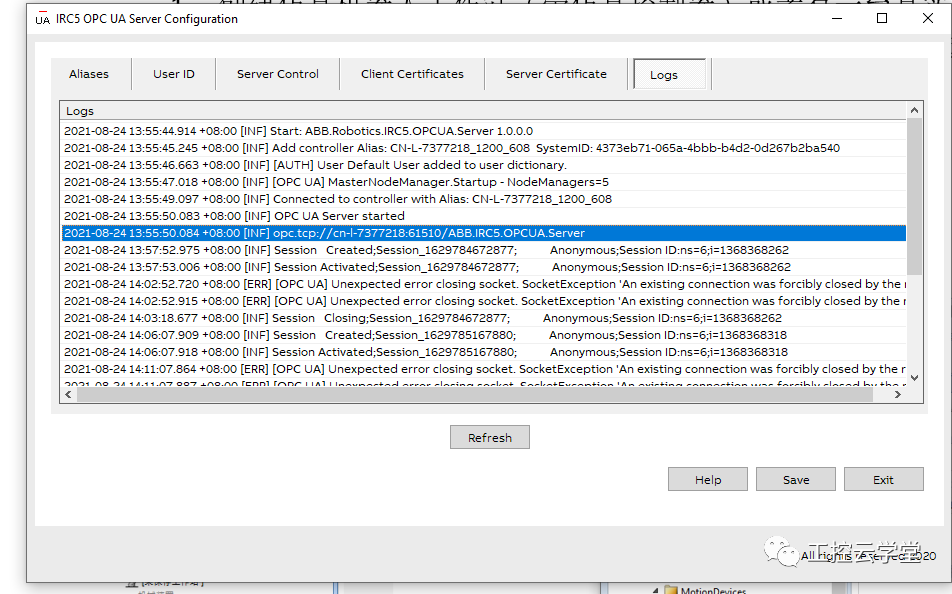
3.Configure the OPC UA SERVER on the PC side according to xxxx, and copy the URL of the OPC UA Server.
4.Create a new empty RobotStudio workstation, and import the same robot model as the real (or another simulation system) including peripheral devices (fences, grippers, welding guns, etc.).
5.Go to RobotStudio – Simulation – Workstation Logic – right-click to create a new OpcUaClient component, enter the URL obtained in step 3 in the server address, and right-click the smart component to connect.
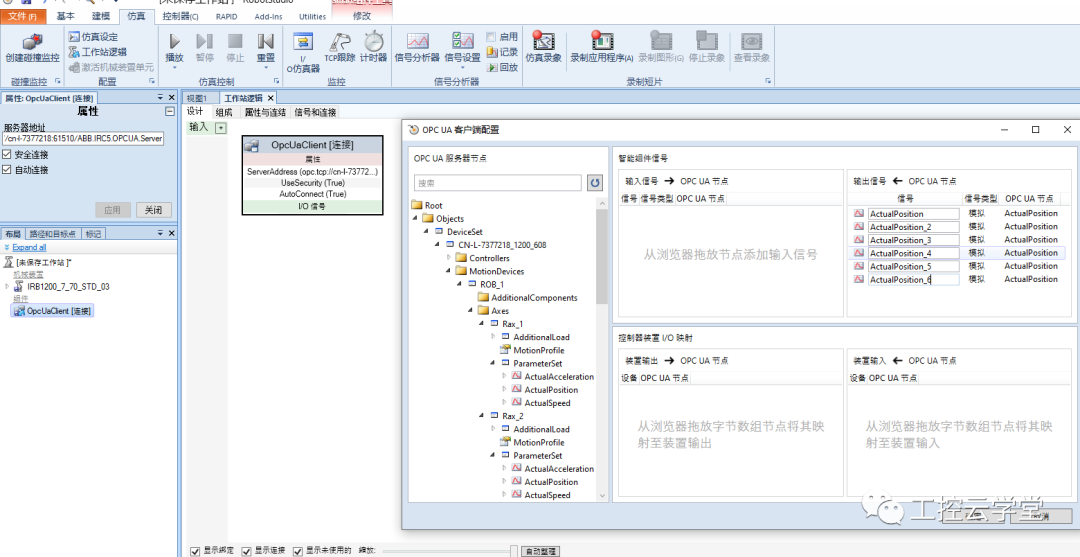
6.The first connection will report an error because the OPC UA server has not authenticated the RobotStudio OPC UA CLIENT. Enter the OPC UA Server configuration software, click refresh in the client Certificates, and click “trust” for the corresponding RobotStudio OPC UA Certificate, then return to RobotStudio and click connect again.
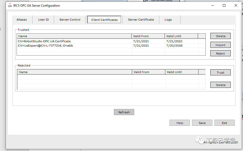
7.Right-click the component, click “Configure”, and find the ActualPosition under the ParameterSet of Rax_1 in the Axes folder from step 5, drag it to the right as the output of this smart component.
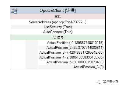
8.Similarly configure other robot axis data, and after configuration, the current axis data of the robot will be displayed (deg).
9.In the workstation logic, insert a JointMover component, and select the corresponding mechanical device as the robot model in the simulation station.
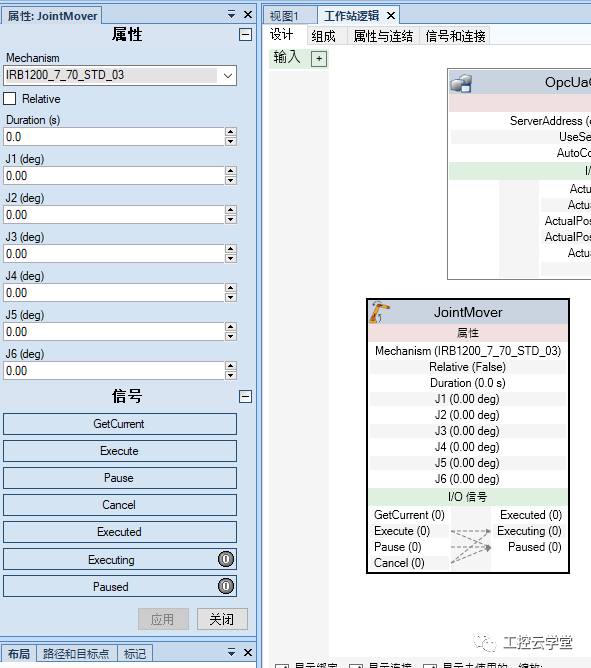
10.Connect the axis data from step 8 with the data from step 9. The JointMover component has a bug, displaying in deg but requires input in radians, so conversion is needed, i.e., convert the output from step 8 to radians before connecting to the input in step 9.
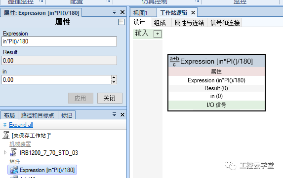
11.Create a new expression component, and enter the following expression in the expression field:in*PI()/180, and click apply. This component will convert deg to rad.
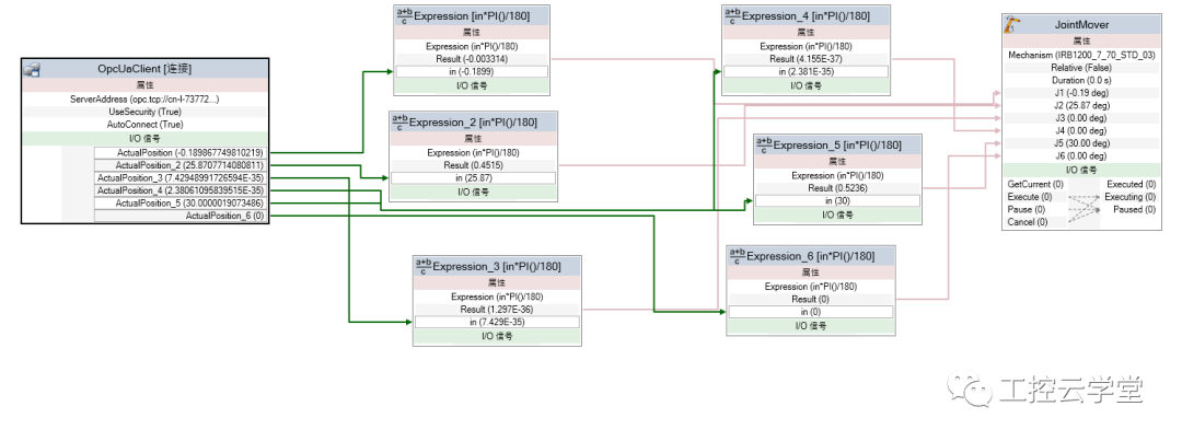
12.Copy several step 11 components, and connect the opcua data with the jointmover data. If the conversion is correct, the axis data in opcua should match the axis data in JointMover.
13.The JointMover needs to be triggered periodically to Execute (rising edge) to move the robot. Insert a timer component, define internal as 0.1s, and connect the output to the Execute of JointMover.
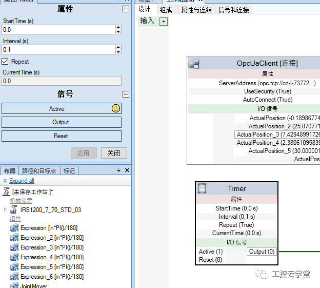
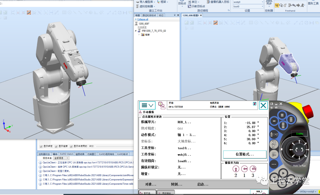
14.At this point, click to start the simulation (because the timer only activates when the simulation is started), and you will see that the robot in this simulation workstation (without a controller) is in real-time digital twin with the real robot.
How to Become an Excellent Industrial Robot Engineer?
Scan for Consultation
▼
Teacher Zuo: 18073180632 (same as WeChat)