In embedded system development, “Firmware” and “Software” are two concepts that are closely related yet fundamentally different. They together constitute the operational logic of a device, but they have clear boundaries in terms of hardware dependency, functional positioning, and development models — firmware is the “soul of the hardware,” responsible for bringing the hardware “to life”; software is the “brain of the system,” responsible for making the hardware “do useful things.” This article uses three typical scenarios: smart wristbands, home routers, and traditional microwave ovens, along with code examples and structural analysis, to clearly demonstrate the core differences between the two.
01
—
Differences Between Firmware and Software
Understanding the basic positioning of the two is the prerequisite for grasping their differences:
Firmware:
Low-level code tightly bound to hardware, directly manipulating hardware registers, initializing peripherals, and driving sensors to work, serves as the “bridge” between hardware and upper-level logic. Its core goal is to “make hardware usable,” and the code is usually embedded in non-volatile storage (such as Flash, ROM), strongly associated with specific hardware models.
Software:
Upper-level business code running on top of firmware, does not directly interact with hardware, and meets user needs (such as data processing, interaction control) by calling firmware interfaces. Its core goal is to “make hardware useful,” and the code can be flexibly iterated and even ported between different hardware (as long as the firmware provides compatible interfaces).
In short: without firmware, hardware is just a pile of electronic components; without software, hardware cannot generate actual value.
02
—
Typical Scenario Case Analysis
Case 1: Smart Wristband (Small Embedded Device without Operating System)
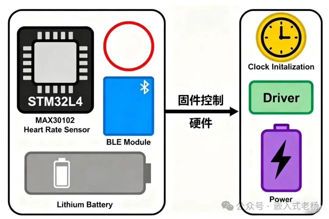
The smart wristband is based on a low-power MCU (such as the STM32L4 series), with limited hardware resources (RAM typically <1MB). The firmware and software layers are clear but have a high degree of coupling, making it a typical sample for understanding “lightweight system division of labor.”
1. Firmware: The “Driver” of Hardware
The firmware directly interacts with the hardware, taking on the responsibility of “making the hardware move,” mainly including:
Hardware Initialization: Configuring the MCU clock and GPIO pin functions (e.g., setting PB0/PB1 as I2C interface to connect to the heart rate sensor) after power-up;
Peripheral Drivers: Operating sensor registers through interfaces like I2C/SPI/UART (e.g., configuring the sampling rate of the MAX30102 heart rate sensor, reading raw data);
Power Management: Monitoring battery voltage, triggering low-power mode when battery level < 10%, shutting down non-essential peripherals.
2. Software: The “Implementer” of Business
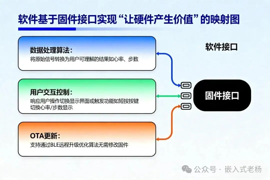
The software is based on firmware interfaces, focusing on “making the hardware generate value,” mainly including:
Data Processing Algorithms: Converting raw signals into user-understandable results (e.g., heart rate, step count);
User Interaction Control: Responding to user actions, switching display interfaces or triggering functions (e.g., short pressing a button to switch between heart rate/step count display);
OTA Updates: Supporting remote upgrades via BLE, optimizing algorithms without modifying firmware.
3. Code Example: Firmware Driver vs Software Algorithm
Taking “Heart Rate Data Processing” as an example, comparing the differences between the two:
Firmware Code (MAX30102 Driver)
Directly operating hardware registers, strongly bound to the sensor model:
// Firmware: MAX30102 sensor driver (hardware related)#include "stm32l4xx_hal.h"#define MAX30102_ADDR 0xAE // Sensor I2C address (hardware fixed)// Initialize sensor (configure registers as defined in hardware manual)void MAX30102_Init(I2C_HandleTypeDef *hi2c) { uint8_t cmd[2] = {0x02, 0x07}; // Register address + configuration value (100Hz sampling rate) HAL_I2C_Master_Transmit(hi2c, MAX30102_ADDR, cmd, 2, 100);} // Read raw PPG signal (directly read registers)void MAX30102_ReadRawData(I2C_HandleTypeDef *hi2c, uint32_t *red_data) { uint8_t buf[3]; cmd[0] = 0x07; // Data register address HAL_I2C_Master_Transmit(hi2c, MAX30102_ADDR, cmd, 1, 100); HAL_I2C_Master_Receive(hi2c, MAX30102_ADDR, buf, 3, 100); *red_data = (buf[0] << 16) | (buf[1] << 8) | buf[2]; // Combine raw data }
Software Code (Heart Rate Calculation Algorithm)
Calling firmware interfaces to process data (simplified example, actual implementation requires more complex algorithms):
// Software: Heart rate calculation (hardware independent, only calls firmware interfaces)#include "max30102_driver.h"float g_prev_heartrate = 70.0;// Note: This is a simplified algorithm for principle demonstration, actual implementation requires autocorrelation analysis, filtering to handle motion artifactsfloat HeartRate_Calculate(uint32_t raw_data) { // 1. Basic filtering (removing high-frequency noise) static float filtered = 0; filtered = 0.8 * filtered + 0.2 * (float)raw_data; // 2. Peak detection (identifying heartbeat cycles) static uint32_t peak_count = 0; static uint32_t last_peak_time = 0; if (filtered > 500 && filtered > (g_prev_heartrate * 1.2)) { // Simple threshold uint32_t current_time = HAL_GetTick(); if (current_time - last_peak_time > 300) { // Exclude interference peak_count++; last_peak_time = current_time; } } // 3. Calculate BPM (beats per minute) static uint32_t start_time = 0; if (HAL_GetTick() - start_time > 1000) { float heartrate = peak_count * 60.0; g_prev_heartrate = 0.7 * g_prev_heartrate + 0.3 * heartrate; // Smoothing peak_count = 0; start_time = HAL_GetTick(); } return g_prev_heartrate;}// Main business logicvoid HeartRate_MainTask(I2C_HandleTypeDef *hi2c) { uint32_t raw; MAX30102_ReadRawData(hi2c, &raw); // Call firmware interface to read data float bpm = HeartRate_Calculate(raw); // Software algorithm processing // Call firmware-provided display API (software does not directly operate OLED registers) OLED_DrawString(20, 20, "HR: %.0f BPM", bpm); }Note: The above algorithm is for principle demonstration only; actual products require complex algorithms such as autocorrelation analysis, digital filter banks, etc., to cope with motion interference and signal noise.
Case 2: Home Router (Complex Device with Linux System)
The router is based on a high-performance SOC (such as Qualcomm IPQ5018), running a Linux system, with clear layers of firmware and software, making it a typical sample for understanding “complex system division of labor.”
1. Firmware: The “Underlying Supporter” of the System
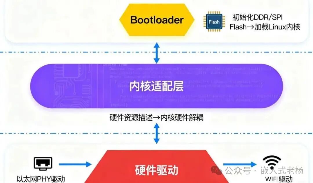
The firmware is deeply customized by the manufacturer, taking on the responsibility of “making hardware compatible with the system,” mainly including:
Bootloader: Initializing DDR memory, SPI Flash, and loading the Linux kernel after power-up;
Hardware Drivers: Providing hardware operation interfaces for the kernel (e.g., Ethernet PHY driver, WiFi RF driver);
Kernel Adaptation Layer: Describing hardware resources through a device tree, decoupling the kernel from hardware.
2. Software: The “Implementer” of User Needs
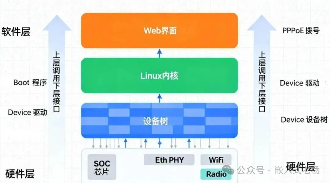
The software runs in the Linux user space, implementing network services through kernel interfaces, mainly including:
PPPoE Dial-up Program: Establishing a connection with the operator by calling kernel interfaces;
Firewall Software (e.g., iptables): Filtering data packets based on rules;
Web Management Interface: Providing a visual configuration entry (e.g., setting WiFi name).
Case 3: Traditional Microwave Oven (Simplistic Device with 8-bit MCU)
The microwave oven is based on an 8-bit MCU (such as PIC16F877A), without an operating system, where firmware and software are physically mixed but logically separable, making it a typical sample for understanding “minimal system division of labor.”
1. Firmware: The “Direct Controller” of Hardware
The firmware directly operates the hardware, with main functions including:
Peripheral Control: Driving heating tube relays, digital tubes, and buzzers through GPIO;
Safety Logic: Detecting door switches, prohibiting heating when the door is not closed properly;
Timer Driver: Achieving precise timing through the MCU timer.
2. Software: The “Logical Executor” of Business
Although the software logic is mixed with firmware, it is essentially “business rules independent of hardware,” such as:
Cooking Mode Control: Automatically setting 70% power and 10 minutes duration when the user selects “Roast Mode”;
Button Response: Recognizing “+/ -” keys to adjust time (increasing or decreasing by 30 seconds each time).
3. Code Example
// Microwave firmware + software mixed code (logical layering example)#include <pic16f877a.h>// Firmware: Hardware abstraction layer (HAL) — isolating hardware operations#define HEAT_RELAY_PIN RB0void HAL_HeatControl(uint8_t power_percent) { // Hardware-level power control (duty cycle adjustment) static uint32_t tick = 0; HEAT_RELAY_PIN = (tick % 1000 < power_percent * 10) ? 1 : 0; tick++;}void HAL_DisplayTime(uint16_t seconds) { // Digital tube display logic (directly operating pins) // ...}// Software: Business logic (does not directly operate hardware)typedef enum { MODE_NORMAL, MODE_ROAST, MODE_DEFROST } CookMode;CookMode g_mode = MODE_NORMAL;uint16_t g_time = 0;void Software_ModeSelect() { if (KEY_MODE_PIN == 0) { // Detect button (through HAL interface) g_mode = (g_mode + 1) % 3; // Business rule: different modes default time g_time = (g_mode == MODE_ROAST) ? 600 : 180; HAL_DisplayTime(g_time); // Call HAL display }}void main() { // Firmware: Initialize hardware TRISB = 0b00000010; // Configure pin direction // ... while(1) { Software_ModeSelect(); // Software logic if (KEY_START_PIN == 0) { while(g_time-- > 0) { // Software: Control power based on mode (not concerned with hardware implementation) uint8_t power = (g_mode == MODE_ROAST) ? 70 : 100; HAL_HeatControl(power); // Call HAL to operate hardware HAL_DisplayTime(g_time); __delay_ms(1000); } } }}Design Suggestion: Even in bare-metal systems, a hardware abstraction layer (HAL) should be used to separate business logic from hardware operations (like the HAL_HeatControl function above), reducing coupling and facilitating maintenance and functional expansion (e.g., adding new modes without modifying hardware code).
03
—
Core Differences Summary
|
Comparison Dimension |
Firmware |
Software |
|
Hardware Dependency |
Strongly bound to specific hardware (e.g., STM32 drivers cannot be used on PIC) |
Low dependency, adapts hardware through firmware interfaces |
|
Functional Positioning |
Low-level control: initializing hardware, driving peripherals, ensuring safety |
Upper-level business: data processing, user interaction, meeting requirements |
|
Code Characteristics |
Small code size, includes register operations, high execution efficiency |
Larger code size, includes business algorithms, complex logic |
|
Storage and Execution |
Embedded in Flash/ROM (non-volatile), runs directly on hardware |
Code stored in Flash, loaded into RAM at runtime, depends on firmware/system operation |
|
Update Method |
Requires specialized tools (JTAG/ISP), high risk (failure may brick the device) |
Can be updated via OTA/USB, low risk (does not affect basic hardware functionality) |
|
Development Roles |
Hardware engineers / driver engineers (need to understand hardware architecture) |
Application engineers / algorithm engineers (no need for hardware details) |
Firmware is the “foundation” of embedded systems, determining the capability boundaries of hardware; software is the “superstructure,” determining the upper limit of hardware value. The significance of clarifying the division of labor between the two lies in:
Improving Efficiency: Hardware engineers focus on firmware stability, while application engineers focus on software iteration;
Reducing Costs: Software updates do not require firmware modifications, and firmware adjustments do not affect software logic;
Enhancing Reliability: Layered isolation reduces fault propagation, hardware issues do not affect business logic.
Previous Articles:
AI Smart Ring: Small Size, Big Technological Energy
Detailed Explanation of Motor Principles and Classifications
Introduction to Peripheral Component Selection and Layout for Switching Power Supplies (DCDC)
Bare-Metal Programming vs RTOS Programming
Development Board “Battle Royale”: Which of the 5 Hot Development Boards (e.g., FiiO, FriendlyARM, Tianmai) is Your “Dish”?
Calculating FreeRTOS Task Stack Size
5 Major State Machine Design Patterns in Embedded Systems
Differences Between MCU and MPU
In-Depth Analysis of AMD Ryzen Embedded 8000 Series Processors
Usage of the “volatile” Keyword in Embedded C Language