In modern automotive electronic systems, dozens or even hundreds of ECUs (Electronic Control Units) communicate and coordinate through bus networks such as CAN, LIN, and FlexRay. To effectively manage the operational states of these ECUs and conserve vehicle battery power, AUTOSAR (Automotive Open System Architecture) has established a comprehensive network management protocol. Among these, the transition mechanism for an ECU from bus sleep mode or prepare bus sleep mode to repeat message state is a core component of the entire network management system.
What is the ECU Network Management State Machine
The ECU network management state machine is a meticulously designed state control system that coordinates the sleep and wake behaviors of all ECUs in the vehicle network. According to AUTOSAR standards, network management includes three main operational modes:
-
Bus Sleep Mode: The ECU is in the lowest power consumption state
-
Prepare Bus Sleep Mode: A transitional state preparing to enter sleep
- Network Mode: Normal communication state, which includes three sub-states
The three sub-states under network mode are:
-
Repeat Message State: Ensures state transitions are visible to other nodes
-
Normal Operation State: Stable working state
-
Ready Sleep State: A buffer state waiting to enter sleep
Characteristics and Functions of Bus Sleep Mode
Bus sleep mode is the lowest power operation state of the ECU. In this mode, the behavioral characteristics of the ECU include:
Communication Characteristics:
-
Does not send any network management messages
-
Does not send any application layer messages
-
Maintains the ability to listen for specific wake-up signals
-
The communication controller enters sleep mode to reduce power consumption
Power Management:
In this state, the ECU reduces power consumption to the minimum level necessary to maintain basic listening functions. This is crucial for vehicles that are parked for extended periods, effectively preventing battery drain.
Wake-Up Mechanism:
Despite being in sleep mode, the ECU remains sensitive to the following wake-up sources:
-
Local wake-up sources (e.g., KL15 power-on signal)
-
Remote wake-up sources (network management messages sent by other ECUs)
-
Special messages such as diagnostic requests
The Key Role of Prepare Bus Sleep Mode
Prepare bus sleep mode plays an important buffering role in CAN and Ethernet networks. The design of this state is intended to ensure that all ECUs have sufficient time to complete their current communication tasks before collectively entering sleep mode.
State Characteristics:
-
The ECU stops sending network management messages
-
Stops sending application layer messages
-
Continues to listen for activity on the bus
-
Prepares for entering full sleep mode
Time Control:
The time the ECU stays in prepare bus sleep mode is controlled by the “Wait Bus-Sleep Time” parameter. This time window ensures:
-
Remaining messages in the send buffer can be transmitted
-
All ECUs can perceive that the network is about to enter sleep mode
- Avoid confusion in network states due to timing inconsistencies
The Core Mechanism of Repeat Message State
The repeat message state is one of the most distinctive designs in ECU network management. Its main function is to ensure that the state transitions of the ECU are fully visible to other nodes in the network.
State Functions:
When an ECU is awakened from sleep or prepare sleep state, it must first enter the repeat message state. In this state:
-
The ECU periodically sends network management messages
-
Simultaneously receives and processes application layer messages
-
Declares its “online” status to other nodes in the network
Message Sending Mechanism:
Depending on the wake-up method, the behavior of the ECU in repeat message state also varies:
-
Remote Wake-Up Situation:
-
The ECU sends network management messages at the standard NM cycle time
-
The sending period is usually several hundred milliseconds
Local Wake-Up Situation:
-
The ECU first enters “fast sending” mode
-
Sends several frames of messages at a shorter period (e.g., tens of milliseconds)
-
Then switches to the standard cycle time
Time Parameter Control:
The duration the ECU stays in repeat message state is determined by the “Repeat Message Time” parameter. The setting of this parameter needs to balance the following factors:
-
Ensuring all ECUs in the network can perceive state changes
-
Avoiding unnecessary power consumption waste
-
Ensuring the reliability of network synchronization
Detailed Process of State Transitions
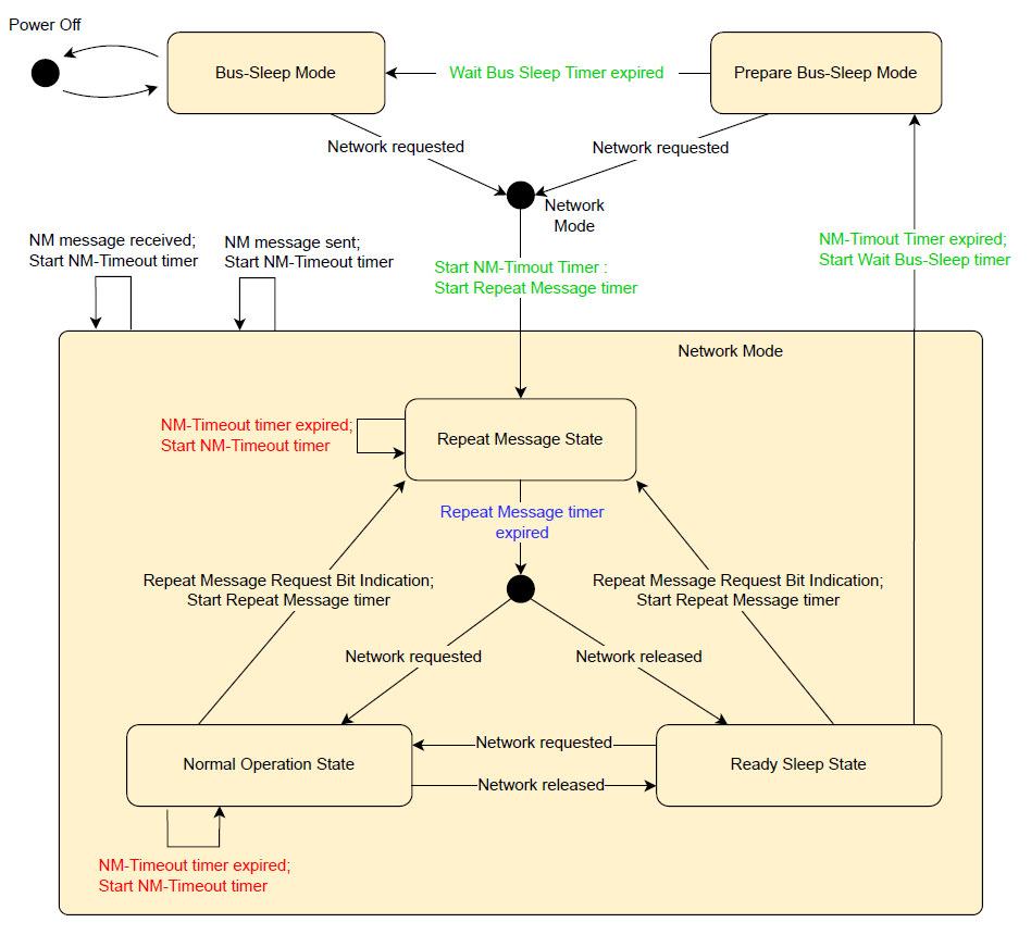
From Bus Sleep Mode to Repeat Message State
Trigger Conditions:
-
Local Wake-Up Source Activation: KL15 power-on, user actions (e.g., pressing the start button), timed wake-up, etc.
-
Remote Wake-Up: Receiving network management messages sent by other ECUs
- Diagnostic Request: Receiving wake-up requests from diagnostic tools
Transition Process:
-
The ECU detects the wake-up signal
-
The communication controller recovers from sleep mode
-
The system initializes necessary network management functions
-
Directly enters repeat message state
- Starts periodically sending network management messages
From Prepare Bus Sleep Mode to Repeat Message State
This transition typically occurs when the ECU suddenly receives a new communication request just before entering sleep.
Trigger Conditions:
-
Network Request Generated: The application layer suddenly needs to communicate
-
Receiving Repeat Message Request: Network management messages sent by other ECUs containing repeat message request bits
- Receiving Network Management Message: Indicates that other ECUs need to keep the network active
Transition Mechanism:
-
The ECU immediately aborts the preparation process to enter sleep
-
Reactivates the sending function of network management messages
-
Enters repeat message state to re-declare network active status
-
Resets related timeout timers
The Role Mechanism of Control Bit Vector
In network management messages, the Control Bit Vector (CBV) plays a key coordinating role. Several important bits are defined as follows:
Repeat Message Request Bit (Bit 0):
-
0: Does not request to enter repeat message state
-
1: Requests other ECUs to enter repeat message state
Active Wake-Up Bit (Bit 4):
-
0: The ECU is passively awakened
-
1: The ECU actively wakes up the network
Partial Network Information Bit (Bit 6):
-
0: The message does not contain partial network request information
-
1: The message contains partial network request information
The combination of these control bits enables precise coordination of network states.
Special Characteristics of Different Bus Protocols
Characteristics of CAN and Ethernet Networks
CAN and UDP network management introduce prepare bus sleep mode in the path from network mode to bus sleep mode. This design ensures that all nodes have time to stop network activity.
The calculation formula for prepare sleep time is:
Total Prepare Sleep Time = Network Timeout Time + Wait Bus-Sleep Time
Considerations in Practical Applications
The Importance of Parameter Configuration
The reliability of the network management system largely depends on the reasonable configuration of parameters:
-
Repeat Message Time: Needs to ensure that the slowest ECU in the network can also perceive state changes
-
Network Timeout Time: Should be greater than the maximum message sending period in the network
- Wait Bus-Sleep Time: Needs to consider network load and ECU response time
Fault Handling Mechanism
When state transitions encounter anomalies, the system needs to have corresponding fault tolerance capabilities:
-
Timeout protection mechanisms to prevent system deadlock
-
State consistency checks to ensure network synchronization
-
Error recovery strategies to handle communication failures
Energy Saving Effects and System Optimization
The ultimate goal of the ECU network management state transition mechanism is to achieve low power operation of the vehicle. By precisely controlling the sleep and wake of ECUs, modern vehicles can:
-
Significantly reduce parking power consumption: From hundreds of milliamps to tens of milliamps
-
Extend battery life: Reduce occurrences of deep discharge
- Improve system reliability: Coordinated state management reduces communication conflicts
The transition mechanism for an ECU from bus sleep mode or prepare bus sleep mode to repeat message state reflects the precision and scientific nature of modern automotive electronic system design. This state mechanism not only addresses the power management issues of multi-ECU systems but also ensures the reliability and consistency of network communication.
As the degree of electronicization in vehicles continues to increase, network management technology is also evolving. Future development directions include smarter partial network management, high-speed network management based on Ethernet, and deep integration with vehicle networking technologies. Understanding these fundamental state transition mechanisms is essential professional knowledge for automotive electronic engineers and serves as an important foundation for building more efficient and reliable in-vehicle network systems.
Reference Source:AUTOSAR Network Management Protocol Specification