This article is reprinted from the Jishu Community
Author: Once a Job’s Tears
Introduction
Recently, I had the privilege of experiencing the Lingdong Micro MM32F5265 development board. The MM32F5260 is equipped with the Arm China “Star-MC1 core” processor, which offers high performance and is aimed at high-reliability application fields such as home appliances and industrial applications.To summarize, here are some highlights:
- Developed by a local team, fully autonomous and controllable, utilizing a completely domestic supply chain;
- Based on the Armv8-M architecture, featuring L1 I-Cache & D-Cache, providing a 20% performance improvement compared to mainstream M3/M4 on the market;
- Achieves zero-latency access to flash memory through I-Cache, with a zero-latency AHB bus matrix supporting multiple concurrent buses;
-
Features a signal interconnection matrix that allows for logical combinations of multiple events, enabling more complex functionalities;
Porting
This porting of RT-Thread references the blog post by “Rice I Call for Extra Rice?”: https://aijishu.com/a/1060000000347637Reference code:https://gitee.com/RiceChen0/mm32f5270_rtt (Thanks to the original author for their contributions)Here, I will focus on the unique aspects:
1. Redirecting Print Output to Virtual Serial Port
Although the Mini-F5265-OB development board does not have an onboard CH340, this does not affect the interaction functionality. The official provides a new method: using the onboard MM32-LINK-OB’s virtual serial port for serial communication.Here is a brief overview of the implementation process:
- The PC connects to the onboard MM32-LINK-OB via USB;
- The onboard MM32-LINK-OB forwards USB data into SWD interface signals and serial tx/rx signals;
- The final signals reach the Mini-F5265-OB development board, enabling serial communication and program flashing;
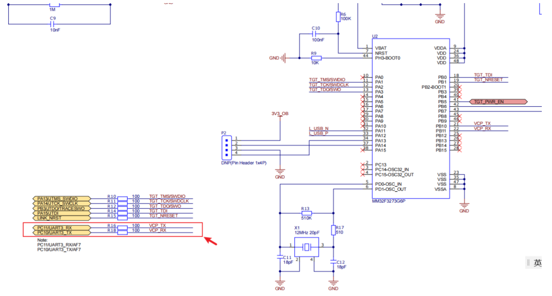
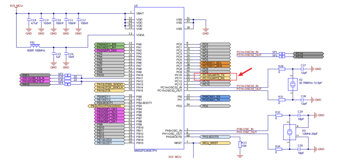
The onboard MM32-LINK-OB is connected as shown in the following diagram: The Mini-F5265-OB development board is connected as shown in the following diagram:
Therefore, the first step in porting is to utilize the virtual serial port.
By examining the schematic diagram above, it can be seen that the virtual serial port uses uart3.
Modify drv_uart.h to add support for uart3:
#if defined(BSP_USING_UART3)#ifndef UART3_CONFIG#define UART3_CONFIG \ { \ .name = "uart3", \ .rx_gpiox = GPIOC, \ .rx_rcc_clock = RCC_AHBPeriph_GPIOC, \ .rx_pin = GPIO_Pin_11, \ .rx_gpio_af = GPIO_AF_7, \ .tx_gpiox = GPIOB, \ .tx_rcc_clock = RCC_AHBPeriph_GPIOC, \ .tx_pin = GPIO_Pin_10, \ .tx_gpio_af = GPIO_AF_7, \ .uart_rcc_clock = RCC_APB1Periph_UART3, \ .uartx = UART3, \ .irq_type = UART3_IRQn, \ }#endif /* UART3_CONFIG */#endif /* BSP_USING_UART3 */Modify drv_uart.c, uart3 uses PC10 and PC11 which need to be initialized:
static int rt_hw_uart_gpio_init(struct mm32_uart_config *cfg){ GPIO_InitTypeDef GPIO_InitStruct; RCC_APB1PeriphClockCmd(RCC_APB1Periph_UART3, ENABLE); RCC_AHBPeriphClockCmd(RCC_AHBPeriph_GPIOC, ENABLE); GPIO_PinAFConfig(GPIOC, GPIO_PinSource10, GPIO_AF_7); GPIO_PinAFConfig(GPIOC, GPIO_PinSource11, GPIO_AF_7); GPIO_StructInit(&GPIO_InitStruct); GPIO_InitStruct.GPIO_Pin = GPIO_Pin_10; GPIO_InitStruct.GPIO_Speed = GPIO_Speed_High; GPIO_InitStruct.GPIO_Mode = GPIO_Mode_AF_PP; GPIO_Init(GPIOC, &GPIO_InitStruct); GPIO_StructInit(&GPIO_InitStruct); GPIO_InitStruct.GPIO_Pin = GPIO_Pin_11; GPIO_InitStruct.GPIO_Mode = GPIO_Mode_IPU; GPIO_Init(GPIOC, &GPIO_InitStruct); return RT_EOK;}Modify drv_uart.c to implement mm32_uart_ops (only key parts are shown here due to space constraints)
static rt_err_t mm32_control(struct rt_serial_device *serial, int cmd, void *arg){ struct mm32_uart *uart; rt_ubase_t ctrl_arg = (rt_ubase_t)arg; RT_ASSERT(serial != RT_NULL); uart = rt_container_of(serial, struct mm32_uart, serial); switch (cmd) { case RT_DEVICE_CTRL_SET_INT: { UART_ITConfig(uart->config->uartx, UART_IT_RX, ENABLE); NVIC_EnableIRQ(uart->config->irq_type); break; } case RT_DEVICE_CTRL_CLR_INT: { UART_ITConfig(uart->config->uartx, UART_IT_RX, DISABLE); NVIC_DisableIRQ(uart->config->irq_type); break; } } return 0;}static int mm32_putc(struct rt_serial_device *serial, char c){ struct mm32_uart *uart; RT_ASSERT(serial != RT_NULL); uart = rt_container_of(serial, struct mm32_uart, serial); UART_SendData(uart->config->uartx, (uint8_t)(c)); while (RESET == UART_GetFlagStatus(uart->config->uartx, UART_FLAG_TXC)) {}; return 1;}static int mm32_getc(struct rt_serial_device *serial){ struct mm32_uart *uart; int ch = -1; RT_ASSERT(serial != RT_NULL); uart = rt_container_of(serial, struct mm32_uart, serial); if(UART_GetFlagStatus(uart->config->uartx, UART_FLAG_RXAVL)) { ch = UART_ReceiveData(uart->config->uartx); return ch; } return -1;}static void uart_isr(struct rt_serial_device *serial){ struct mm32_uart *uart; RT_ASSERT(serial != RT_NULL); uart = rt_container_of(serial, struct mm32_uart, serial); if(SET == UART_GetFlagStatus(uart->config->uartx, UART_IT_RX)) { rt_hw_serial_isr(serial, RT_SERIAL_EVENT_RX_IND); }}void UART3_IRQHandler(void){ rt_interrupt_enter(); uart_isr(&(uart_obj[UART3_INDEX].serial)); rt_interrupt_leave();}2. Adding HAL Library and Other Files
- Find the HAL_Lib folder from the official example materials and copy the header and source files into the project’s libraries/drivers directory.
- Modify libraries/drivers mm32f5260.h to define the macro “USE_STDPERIPH_DRIVER”. (Note that the default provided by the official does not define this macro, it needs to be defined for the standard peripheral driver library to compile.)
- Create hal_common.h in the libraries/drivers directory and include “hal_conf.h” in it, so that the HAL layer function interfaces can be called externally.
- Copy the official core_starmc1.h to the project’s libraries/libraries/CMSIS/Include directory, replacing the original core_star.h.
- Organize the files from the official source folder into the libraries and mdk directories.
Note: The above only lists key parts; for more details, see the code repository.
3. Implementing SysTick
Unlike before, the SDK used this time has already implemented the system clock initialization (system_mm32f5260.c), so we only need to implement SysTick, as shown in the code below:
void SysTick_Init(void){ uint32_t reload = 0; SysTick->CTRL &= (uint32_t)0xFFFFFFFB; reload = CLOCK_SYSTICK_FREQ/RT_TICK_PER_SECOND; reload--; SysTick->CTRL |= SysTick_CTRL_TICKINT_Msk; SysTick->LOAD = reload; SysTick->CTRL |= SysTick_CTRL_ENABLE_Msk;}void SysTick_Handler(void){ /* enter interrupt */ rt_interrupt_enter(); rt_tick_increase(); /* leave interrupt */ rt_interrupt_leave();}void rt_hw_board_init(){ SysTick_Init(); SystemClock_Config();#if defined(RT_USING_HEAP) rt_system_heap_init(HEAP_BEGIN, (void *)HEAP_END);#endif#ifdef RT_USING_SERIAL extern int rt_hw_uart_init(void); rt_hw_uart_init();#endif#if defined(RT_USING_CONSOLE) && defined(RT_USING_DEVICE) rt_console_set_device(RT_CONSOLE_DEVICE_NAME);#endif#ifdef RT_USING_COMPONENTS_INIT rt_components_board_init();#endif}Porting Results
At this point, the porting work is basically complete.
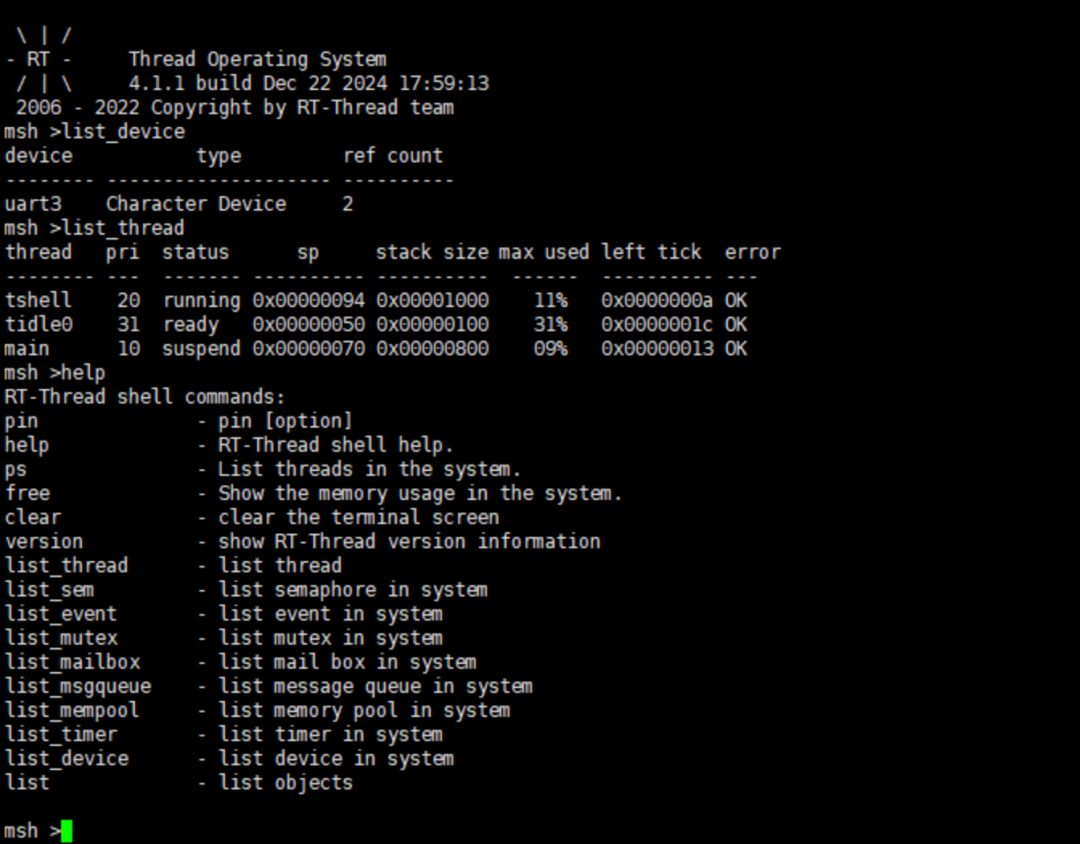
Compile and flash, and you can see the output from RT-Thread:

On the development board, you can see LED2 blinking once every 500ms.
Conclusion
The modifications made during this porting process were minimal, mainly due to changes in the SDK. Here, we can see Lingdong Micro’s efforts in maintaining the HAL library. After all, the stronger the HAL layer compatibility, the more potential users it can attract, saving users time in familiarizing themselves with the SDK, which is also an essential path for domestic chip replacement.
Finally, thanks to Lingdong Micro and the Jishu Community for providing the platform, and I wish domestic chips continued success.
Repository code:https://gitee.com/sakura96888/mm32f5260_rttRecommended Reading:
-
Development Board Review | Unboxing Experience from the Maker Summit
-
Development Board Review | Beginner’s Unboxing & Hands-on Experience
-
Development Board Review | SiRider S1 Unboxing Experience
Reprinted from | Jishu Community
Copyright belongs to the original author. If there is any infringement, please contact for deletion.