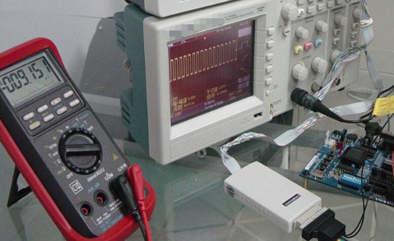
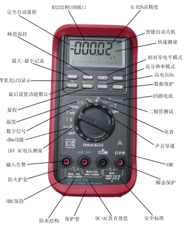
A digital multimeter is a commonly used electronic instrument in electrical measurements. It has many special functions, but its main functions are to measure voltage, resistance, and current.
How to measure voltage, resistance, and current with a digital multimeter?
The most basic function of a digital multimeter is measuring voltage. A typical direct current voltage source is a battery, such as an automotive battery. Alternating current voltage is usually generated by a generator, and the most common source of alternating current voltage is the outlets on the walls of our homes. Some devices convert alternating current to direct current, such as TVs, audio systems, VCRs, and computers, using rectifiers plugged into wall outlets to convert AC to DC; the direct current voltage is the power required by these electronic devices.

Testing voltage is usually the first step in solving circuit problems. If there is no voltage or the voltage is too low or too high, the power issue must be resolved before further checks. The waveform of alternating current voltage can be sinusoidal (sine wave) or non-sinusoidal (sawtooth, square wave, etc.). Many digital multimeters (such as OI857Ⅱ and OI859CFⅡ) can display the “rms” (root mean square) value of alternating current voltage. The effective value is equivalent to the value of direct current voltage. However, most digital multimeters (such as BM805) only have the “average responding” function, which can provide the effective value when inputting a pure sine wave. This type of digital multimeter cannot accurately measure the effective value of non-sinusoidal waves. Digital multimeters with true RMS function can accurately measure the true effective value of non-sinusoidal waves.
The crest factor is the ratio of the peak value of a signal to its effective value. The ability of a digital multimeter to measure alternating current voltage is limited by the frequency of the signal being measured. Most digital multimeters can accurately measure alternating current voltage in the range of 50Hz to 500Hz, but some digital multimeters can measure AC at bandwidths of several hundred kilohertz (for example, the OI859CFⅡ can measure up to 100KHz).
Steps to measure voltage with a digital multimeter:
1. Select the desired range and setting;
2. Insert the black probe into the COM port and the red probe into the voltage input port;
3. Connect the probe tips across the load or power supply (and in the circuit);
4. Observe the reading and confirm the unit.
When measuring voltage, to correctly read the polarity (±) of the direct current voltage, connect the red probe to the positive side of the circuit and the black probe to the negative side or circuit ground. If the connections are reversed, a digital multimeter with automatic polarity switching function will display a negative sign to indicate negative polarity. In this case, if it is an analog multimeter, there is a risk of damaging the multimeter. When measuring high voltage, high voltage probes, such as those used in TV and VCR repairs, which can withstand 40kV high voltage, must be used. However, these high voltage probes (for example, OIHVP40) cannot be used in high voltage situations accompanied by high energy; they can only be applied in low energy situations.
The resistance value generally varies widely, from a few milliohms (mΩ) of contact resistance to several billion ohms of insulation resistance. Many digital multimeters can measure resistance as low as 0.1 ohms and as high as 300 megaohms. For extremely high resistance, a digital multimeter will usually display “OL,” indicating that the measured resistance exceeds the range. When measuring open circuits, it will also display “OL.” Resistance must be measured with the circuit power turned off; otherwise, it may damage the meter or the circuit board. Some digital multimeters provide protection functions when voltage signals are mistakenly applied in resistance mode. Different models of digital multimeters have different protective capabilities.
When performing precise measurements of low resistance, the resistance of the measuring leads must be subtracted from the measurement value. The typical resistance of test leads is between 0.2Ω and 0.5Ω. If the resistance of the test leads exceeds 1Ω, the test leads should be replaced. If a digital multimeter provides less than 0.6V of direct current voltage for measuring resistance, it can measure the resistance values of components isolated by diodes or semiconductors on circuit boards without having to remove the resistors.
Steps to measure resistance with a digital multimeter (make sure to turn off the power when testing resistance):
1. Turn off the circuit power;
2. Select the resistance range;
3. Insert the black probe into the COM socket and the red probe into the resistance testing socket;
4. Connect the probe tips to both ends of the component or circuit being measured;
5. Observe the reading and note the unit: ohms (Ω), kilo-ohms (kΩ), or mega-ohms (MΩ).
Continuity testing distinguishes open circuits from short circuits through quick resistance measurements. Digital multimeters equipped with continuity beeping features make continuity testing simpler and quicker. When a short circuit is detected, the digital multimeter emits a beep, so there is no need to look at the display. Different models of digital multimeters have different triggering resistance values.
Diodes act like electronic switches; they conduct when the voltage exceeds a certain value. The typical conduction voltage for silicon diodes is 0.6V, and diodes only allow current to flow in one direction. When checking a diode or a junction, the digital multimeter will not only provide a wide range of readings but also supply a driving current greater than 50mA. When measuring the resistance of circuits containing diodes, the testing voltage of the digital multimeter will be less than 0.6V to prevent the junction from conducting. When selecting diode testing, the testing voltage increases to check the function of the diode or semiconductor junction. Some digital multimeters have diode testing functions, which measure and display the actual voltage drop across the diode; the voltage drop across the silicon junction during forward testing should be less than 0.7V, and during reverse testing, the circuit should be open.
Measuring current with a digital multimeter is a very important function that differs from measuring other quantities. The direct current measurement method involves connecting the digital multimeter directly in series with the circuit being measured, allowing the current to flow directly through the internal circuit of the digital multimeter. The indirect measurement method does not require opening the circuit and connecting the digital multimeter in series with the circuit; it requires the use of current clamps or current probes.
Steps for direct current measurement with a digital multimeter:
1. Turn off the circuit power;
2. Disconnect or unsolder the circuit to insert the digital multimeter in series;
3. Select the appropriate AC (A~) or DC (A–) range;
4. Insert the black probe into the COM port and the red probe into the 10 amp socket (or 300 milliamp socket). The choice of socket mainly depends on the expected measurement value;
5. Connect the probes in series to the disconnected part of the circuit;
6. Turn on the circuit power;
7. Observe the reading and note the unit.
Measuring current with a digital multimeter is most prone to damage; a common mistake is placing the test leads in the current socket while attempting to measure voltage, which is a frequent error in probe connections. At this point, the small internal resistance of the digital multimeter can cause a short circuit of the voltage source, leading to a large current flowing through the digital multimeter. If the digital multimeter does not have sufficient protection, it may damage both the meter and the circuit and also pose a risk to the operator. If it is a high-voltage circuit (480 volts or higher), it poses even greater danger. Therefore, the digital multimeter should have a sufficiently large current input protection fuse; a digital multimeter without a current input fuse cannot be used in high-energy circuits (>240Vac). For digital multimeters with fuses, the fuse should have a large enough capacity to handle high-energy failures. The fuse’s rated voltage should be greater than the maximum voltage you expect; for example, a 20A/250V fuse in a digital multimeter cannot provide protection when measuring a 480V circuit; a 20A/600V fuse can provide protection when measuring a 480V circuit. Some digital multimeters have a probe connection error beeping alarm function; for instance, OI857Ⅱ and OI859CFⅡ require careful attention during current measurement: when disconnecting or unsoldering the circuit to test, the power to the circuit must be turned off; even small currents can be dangerous; do not attempt to measure voltage with the test leads plugged into the current socket, as this can damage the digital multimeter or endanger personal safety.

Enhancing the Range and Capability of Current Testing with Digital Multimeters:
If you need to measure current values exceeding the range of the digital multimeter or if site conditions do not allow for circuit disconnection for current measurement, current clamps or current probes are very convenient for high current testing (usually greater than 2A) when high precision is not required. Current clamps measure the current by encircling the wire and convert it to a value that the digital multimeter can process.
There are two basic types of current probes: 1. Current transformers, which are used only for AC measurements. 2. Hall effect probes, which can measure both AC and DC currents.
Current transformers typically use 1 milliamp to represent 1 ampere; a current value of 100 amperes will be converted to 100 milliamps, allowing safe measurement with a digital multimeter. Connect the wire to the “mA” and “Com” sockets, and turn the function selection knob to the AC milliamp range. Hall effect probes use 1 millivolt to represent 1 ampere of AC or DC value. For example, 100 amperes of AC current will be converted to 100 millivolts of AC voltage. Connect the test leads to the “V” and “Com” sockets, and turn the function selection knob to the “V” or “mV” range. At this point, the multimeter uses 1 millivolt of voltage to represent 1 ampere of current. A typical current transformer probe, such as K2, displays 1mA to represent an actual 1A signal. A typical Hall effect probe, such as K1, can test very high AC or DC currents, converting current into a voltage signal; a display of 1mV of voltage represents 1A of actual current.
For more product details, please contact us through the following:
Email: [email protected]
Phone: 010-62176775/62176785
Consultation WeChat: 13699295117


Marine Instruments
Dedicated to the field of electronic testing and maintenance!


