In modern electronic systems, communication between devices is a key aspect of achieving complex functionalities. SPI (Serial Peripheral Interface) is an efficient and flexible synchronous serial communication protocol widely used for data exchange between microcontrollers (MCUs) and various peripheral devices. This article will provide a detailed introduction to the working principles of the SPI protocol, its signal composition, communication process, advantages and disadvantages, along with illustrative diagrams.
1. Overview of the SPI Protocol
The SPI protocol is a full-duplex synchronous serial communication protocol proposed by Motorola in the 1980s. It is primarily used for communication between a master device and slave devices, supporting high-speed data transmission and is widely applied in embedded systems, sensor networks, memory interfaces, and other fields.

2. Composition of SPI Signals
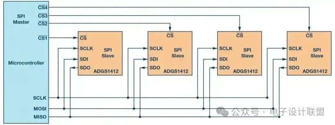
SPI communication is achieved through four signal lines, each with a specific function:
-
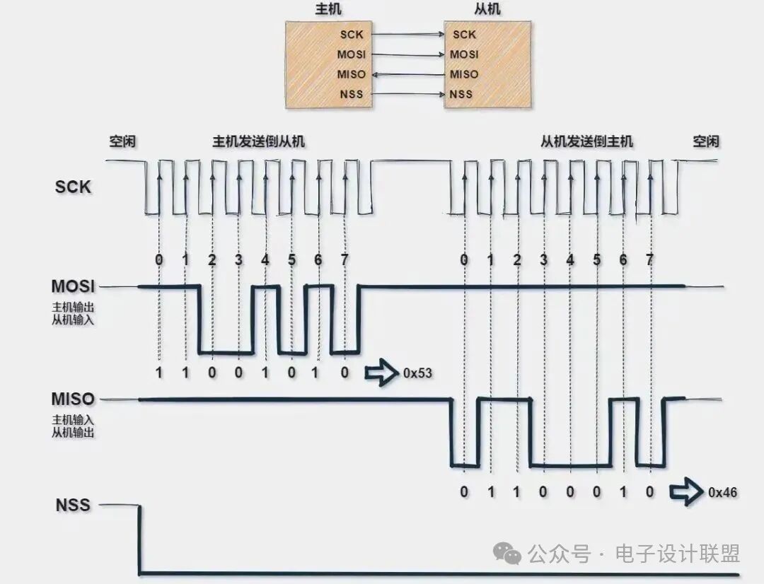
SCLK (Serial Clock Line) is the clock signal line provided by the master device, used to synchronize data transmission. The frequency and phase of the clock signal determine the timing of data sampling and transmission.
-
MOSI (Master Out Slave In) is the master device’s data output line, used to send data from the master device to the slave device. Data is transmitted bit by bit under the control of the clock signal.
-
MISO (Master In Slave Out) is the master device’s data input line, used to send data from the slave device to the master device. Data transmission also occurs under the control of the clock signal.
-
CS (Chip Select) is the chip select signal line, used to select a specific slave device. The master device activates the corresponding slave device by pulling down a CS line, allowing it to participate in communication.
3. SPI Communication Process
The SPI communication process strictly follows timing control to ensure accurate data transmission. The following are the detailed steps of the communication process:
(1) Selecting the Slave Device
The master device selects the target slave device by pulling down a CS line. Only the selected slave device will respond to communication requests. For example, if there are multiple slave devices in the system, the master device can communicate with them separately through different CS lines.
(2) Clock Signal Synchronization
The master device begins sending the clock signal (SCLK), providing a synchronization reference for data transmission. The frequency and phase of the clock signal determine the timing of data sampling and transmission.
(3) Data Transmission
Under the control of the clock signal, the master device sends data to the slave device via the MOSI line, while the slave device can send data back to the master device via the MISO line. The SPI protocol supports full-duplex communication, allowing both the master and slave devices to transmit data simultaneously.
(4) Ending Communication
The master device pulls the CS line high, ending the current communication. The slave device stops responding once the CS line is pulled high, waiting for the next communication request.

4. SPI Operating Modes
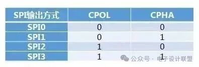
The SPI protocol defines four operating modes, determined by the clock polarity (CPOL) and clock phase (CPHA) parameters. The master and slave devices must operate in the same mode to ensure correct communication.
(1) Mode 0 (CPOL=0, CPHA=0)
-
Clock Polarity (CPOL)=0: The clock signal is low when idle.
-
Clock Phase (CPHA)=0: Data is sampled on the rising edge of the clock signal and sent on the falling edge.
(2) Mode 1 (CPOL=0, CPHA=1)
-
Clock Polarity (CPOL)=0: The clock signal is low when idle.
-
Clock Phase (CPHA)=1: Data is sampled on the falling edge of the clock signal and sent on the rising edge.
(3) Mode 2 (CPOL=1, CPHA=0)
-
Clock Polarity (CPOL)=1: The clock signal is high when idle.
-
Clock Phase (CPHA)=0: Data is sampled on the falling edge of the clock signal and sent on the rising edge.
(4) Mode 3 (CPOL=1, CPHA=1)
-
Clock Polarity (CPOL)=1: The clock signal is high when idle.
-
Clock Phase (CPHA)=1: Data is sampled on the rising edge of the clock signal and sent on the falling edge.
5. Advantages of the SPI Protocol
Due to its efficient and flexible characteristics, the SPI protocol is widely used in embedded systems. Its main advantages include:
-
High-Speed Data TransmissionThe SPI protocol supports high clock frequencies, with data transmission rates reaching several tens of Mbps, suitable for applications requiring high real-time performance.
-
Full-Duplex CommunicationThe master and slave devices can send and receive data simultaneously, improving communication efficiency.
-
Flexible Data LengthThe SPI protocol supports data transmission of arbitrary lengths, not limited to 8 bits, allowing flexible configuration based on actual needs.
-
Simple Hardware InterfaceThe SPI protocol requires only four signal lines for communication, making hardware connections simple and easy to implement.
6. Disadvantages of the SPI Protocol
Despite its many advantages, the SPI protocol also has some limitations:
-
Only Supports Single Master DeviceThe SPI protocol does not support multi-master communication; there can only be one master device in the system, limiting system scalability.
-
More Signal Lines RequiredCompared to the I2C protocol, the SPI protocol requires four signal lines, increasing the complexity of hardware wiring.
-
Lacks Error Detection MechanismThe SPI protocol does not have a built-in error detection and acknowledgment mechanism, making it impossible to confirm whether data has been correctly received, resulting in relatively low reliability.
-
Limited Transmission DistanceThe SPI protocol is mainly used for short-distance communication within a board, with limited transmission distances, making it unsuitable for long-distance communication scenarios.
7. Quality Requirements for SPI Signals
To ensure reliable communication, the quality of SPI signals must meet the following requirements:
-
Level StandardsThe high and low levels of the signals must comply with the standards specified by the protocol to ensure accurate data sampling.
-
Clock FrequencyThe frequency of the clock signal must be stable and accurate to avoid data transmission errors.
-
Timing RequirementsThe setup and hold times of the signals must meet the protocol requirements to ensure data is sampled at the correct moments.
-
Rise and Fall TimesThe rise and fall times of the signals must comply with specifications to avoid signal distortion and misjudgment.
8. Conclusion
The SPI protocol, as an efficient synchronous serial communication protocol, has been widely used in embedded systems. It achieves high-speed data transmission through a simple hardware interface and flexible communication mechanisms. However, the SPI protocol also has some limitations, such as only supporting a single master device and lacking error detection mechanisms. In practical applications, designers need to choose communication protocols wisely based on specific requirements and strictly control signal quality to ensure system reliability and stability.
Disclaimer:This content is sourced from the internet. If there are any issues regarding the content, copyright, or other matters, please contact the staff via WeChat (13237418207), and we will promptly address the deletion!Submissions/Recruitment/Advertising/Course Cooperation/Resource Exchange, please add WeChat: 13237418207
[Recommended Materials] Switching Power Supply Case and Learning Material Package
2025-07-31
Step-by-step guide to selecting capacitors: Full analysis of key parameters
2025-07-31
EDA toolkit for hardware engineers: List of specialized tools
2025-07-31

Scan to add customer service WeChat, note “Join Group” to pull you into the official exclusive technical WeChat group of Fanyi Education, to discuss technical issues and insights with many electronic technology experts~
Share, Like, and Support ❤️ with a “three-click”!