(Click the public account above to quickly follow)
Source: Wang Dongyu
Link: http://wangdy.blog.51cto.com/3845563/1588379
OSI Reference Model
OSI RM: Open System Interconnection Reference Model
The OSI reference model has the following advantages:
-
Simplifies related network operations;
-
Provides compatibility and standard interfaces between devices;
-
Promotes standardization efforts;
-
Structurally separable;
-
Easy to implement and maintain.
Since the 1960s, computer networks have grown rapidly. Major manufacturers have introduced their own network architecture systems and standards, such as IBM’s SNA, Novell’s IPX/SPX protocol, Apple’s AppleTalk protocol, DEC’s DECnet, and the widely popular TCP/IP protocol. At the same time, manufacturers have produced different hardware and software for their protocols. The joint efforts of various manufacturers have promoted the rapid development of network technology and the rapid increase in the variety of network devices. However, the coexistence of multiple protocols has made networks increasingly complex; moreover, most network devices from different manufacturers are not compatible, making communication difficult.
To solve the compatibility issue between networks and help manufacturers produce compatible network devices, the International Organization for Standardization (ISO) proposed the OSI RM (Open System Interconnection Reference Model) in 1984. The OSI reference model quickly became the foundational model for computer network communication. The design of the OSI reference model follows these principles: there are clear boundaries between layers, each layer implements specific functions; the division of layers facilitates the formulation of international standard protocols; the number of layers should be sufficient to avoid functional duplication among layers.
OSI Layering
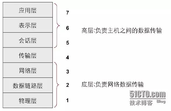
Typically, the first to third layers of the OSI reference model are referred to as the lower layers, also known as the media layers, which are responsible for data transmission across the network. Network interconnection devices are often located in these lower three layers, implemented through hardware and software. The fifth to seventh layers of the OSI reference model are referred to as the upper layers, also known as the host layers, which ensure the correct transmission of data, implemented through software.
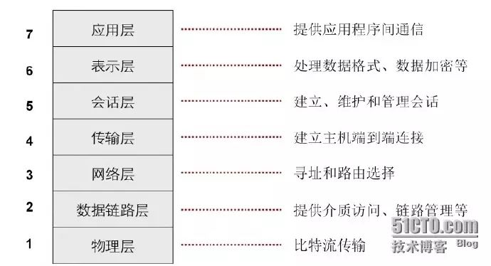
Functions of the seven layers of OSI:
TCP/IP Protocol Stack
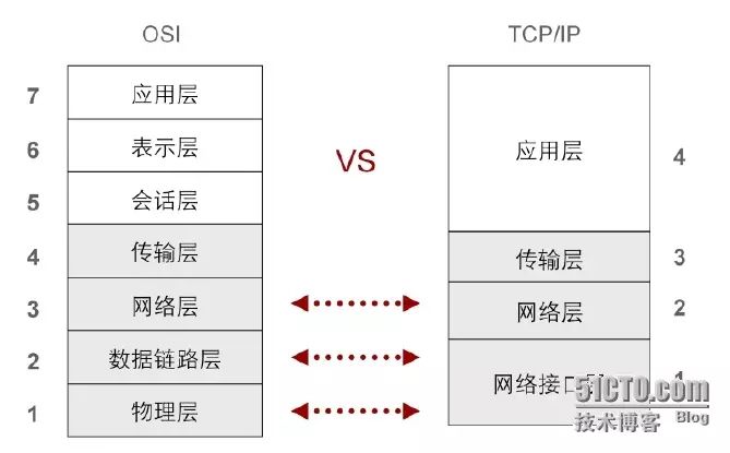
Due to the complexity of the OSI model and protocols, it has not been widely adopted.
In contrast, the TCP/IP (Transfer Control Protocol/Internet Protocol) model has been widely used in practice due to its openness and ease of use, and the TCP/IP protocol stack has become the mainstream protocol of the Internet.

The various layers of the TCP/IP model correspond to different protocols. The TCP/IP protocol stack is a collection of data communication protocols that includes many protocols. The name of the protocol stack comes from its two main protocols, TCP (Transmission Control Protocol) and IP (Internet Protocol). The TCP/IP protocol stack is responsible for ensuring communication between network devices. It is a set of rules that specify how information is transmitted across the network.
Inter-layer Communication and Data Encapsulation in TCP/IP
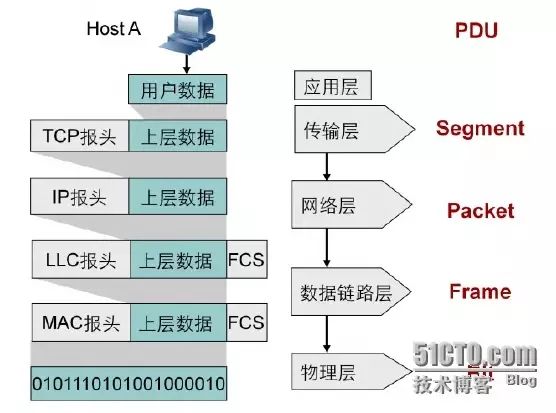
Each layer of TCP/IP allows data to be transmitted across the network. These layers exchange information using PDU (Protocol Data Units) to ensure communication between network devices.
A. Data added to the transport layer with the TCP header is called a segment;
B. The segment is passed to the network layer, which adds the IP header, resulting in a PDU called a packet;
C. The packet is passed to the data link layer, which encapsulates it with the data link layer header, resulting in a PDU called a frame;
D. The frame is converted to bits and transmitted through the network medium.
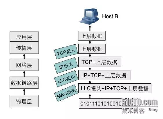
This process of passing data down the protocol stack while adding headers and trailers is called encapsulation. After the data has been encapsulated and transmitted over the network, the receiving device will remove the added information and determine how to pass the data up the protocol stack to the appropriate application based on the information in the headers. This process is called decapsulation. Communication between peer layers of different devices relies on encapsulation and decapsulation.
Physical Layer
Functions of the physical layer:
-
Specifies the type of medium, interface type, signaling type;
-
Defines the electrical, mechanical, procedural, and functional requirements for activating, maintaining, and deactivating physical links between terminal systems;
-
Specifies characteristics such as levels, data rates, maximum transmission distances, and physical connectors.
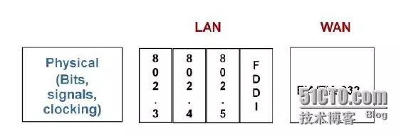
The physical layer standards specify the physical media and connectors used to connect devices to the physical media.
As shown in the figure, commonly used physical layer standards for local area networks include the IEEE specified Ethernet standard 802.3, Token Bus standard 802.4, Token Ring standard 802.5, and the fiber distributed data interface (FDDI) standard developed by the ANSI X3T9.5 committee. Commonly used physical layer standards for wide area networks include the EIA/TIA public physical layer interface standard EIA/TIA-232 (i.e., RS-232), serial line interface standards V.24 and V.35 developed by the ITU, and standards G.703 related to various digital interfaces’ physical and electrical characteristics.
Physical layer media and devices:
Physical layer media:
-
Coaxial cable
-
Twisted pair
-
Fiber optic
-
Radio waves
Coaxial cable:
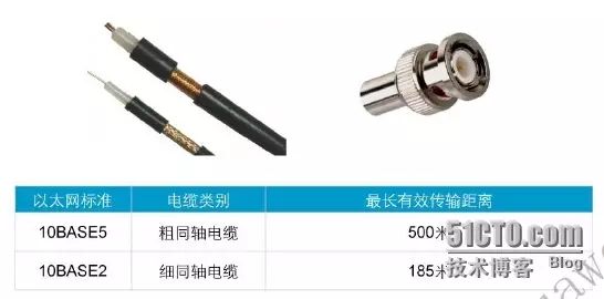
Coaxial cable is an early used transmission medium, with two standards: 10BASE2 and 10BASE5. Both standards support a transmission rate of 10Mbps, with maximum transmission distances of 185 meters and 500 meters, respectively. The coaxial cables used in 10BASE5 and 10BASE2 have diameters of 9.5mm and 5mm, respectively, so the former is called thick cable and the latter thin cable. Generally, 10BASE2 coaxial cables use BNC connectors, while 10BASE5 coaxial cables use N-type connectors. Currently, the 10Mbps transmission rate is no longer sufficient for enterprise network needs, so coaxial cables are rarely used in modern enterprise networks.
Twisted pair:
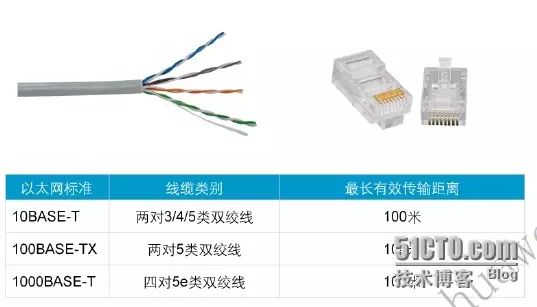
Twisted pair uses a pair of insulated metal wires twisted together to resist some external electromagnetic interference. By twisting two insulated copper wires together at a certain density, the degree of signal interference can be reduced, as the electromagnetic waves radiated by each wire are canceled out by the waves emitted from the other wire, hence the name “twisted pair”.
Compared to coaxial cables, twisted pair (twisted pair) has lower manufacturing and deployment costs, which is why it is widely used in enterprise networks. Twisted pair can be divided into shielded twisted pair (STP) and unshielded twisted pair (UTP). Shielded twisted pair has a metal shielding layer between the twisted pair and the outer insulating sheath to shield against electromagnetic interference.
There are many types of twisted pair cables, and the transmission rates supported by different types are generally different. For example, Category 3 twisted pair supports a transmission rate of 10Mbps; Category 5 twisted pair supports a transmission rate of 100Mbps, meeting the fast Ethernet standard; Category 5e and higher categories support Gigabit Ethernet transmission.
Twisted pair wiring sequences:
568A wiring: 1-Green White, 2-Green, 3-Orange White, 4-Blue, 5-Blue White, 6-Orange, 7-Brown White, 8-Brown 568B wiring: 1-Orange White, 2-Orange, 3-Green White, 4-Blue, 5-Blue White, 6-Green, 7-Brown White, 8-Brown
According to the different connections of network devices at both ends, network cables are divided into straight-through cables (parallel cables) and crossover cables.
Straight-through cables (parallel cables) are made according to the aforementioned 568A or 568B standards (i.e., the wiring at both ends of the twisted pair is the same; the 568A wiring is not commonly used, and the mainstream is now 568B wiring).
Crossover cables keep the wiring of one end unchanged while swapping pairs 1 and 3, and pairs 2 and 5 on the other end.
Applications of straight-through and crossover cables:
1. Use crossover cables to connect devices of the same type and straight-through cables to connect devices of different types; 2. Routers and PCs belong to DTE (Data Terminal Equipment) types, while switches and hubs belong to DCE (Data Circuit-terminating Equipment) types.
Fiber optic:
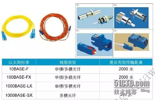
Twisted pair and coaxial cables transmit data using electrical signals, while fiber optics transmit data using light signals. Fiber optics support transmission rates including 10Mbps, 100Mbps, 1Gbps, 10Gbps, and even higher. Depending on the mode of light transmission, fiber optics can be divided into single-mode and multi-mode. Single-mode fiber transmits only one mode of light and does not suffer from modal dispersion, making it suitable for long-distance high-speed transmission. Multi-mode fiber allows different modes of light to be transmitted over one fiber, but due to significant modal dispersion, it is mainly used for short-distance transmission in local area networks. There are many types of fiber optic connectors, commonly including ST, FC, SC, and LC connectors.
Serial cables:
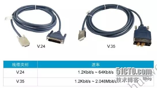
Various serial cables are often used in network communications. The commonly used serial cable standard is RS-232, which is also the recommended standard. However, RS-232 has limited transmission rates and a transmission distance of only 6 meters. Other serial cable standards can support longer transmission distances, such as RS-422 and RS-485, which can reach up to 1200 meters. RS-422 and RS-485 serial cables typically use V.35 connectors, which have been obsolete since the 1980s but are still used in traditional networks like frame relay and ATM. V.24 is the European version of the RS-232 standard. RS-232 itself does not define connector standards, with common connector types being DB-9 and DB-25. Nowadays, RS-232 has gradually been replaced by newer standards like FireWire and USB, and new products and devices commonly use the USB standard.
Collision domains:
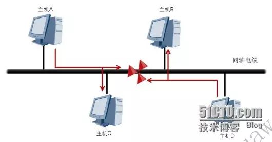
As shown in the figure, in a 10BASE5 Ethernet, each host communicates with other hosts using the same coaxial cable, which is referred to as a shared medium, and the corresponding network is called a shared medium network or simply a shared network. In a shared network, when different hosts send data simultaneously, signal collisions may occur. The method to resolve this issue is generally to use Carrier Sense Multiple Access with Collision Detection (CSMA/CD).
The basic working process of CSMA/CD is as follows:
1. The terminal continuously detects the status of the shared line. If the line is idle, it can send data; if the line is busy, it waits for a while and continues to detect (the waiting time is determined by the backoff algorithm). 2. If another device sends data simultaneously, the data from both devices will collide. 3. The terminal device detects the collision and immediately stops sending its data, sending a special blocking message to reinforce the collision signal, allowing other stations on the line to detect the collision as soon as possible. 4. After detecting the collision, the terminal device waits for a while before sending data again (the waiting time is determined by the backoff algorithm).
The working principle of CSMA/CD can be summarized as follows: listen before sending, send while listening, stop sending upon collision, and resend after a random delay.
Physical layer devices: Repeaters and hubs
Data Link Layer
The data link layer is divided into the MAC sublayer and LLC sublayer
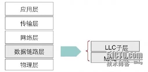
MAC Sub-layer: Media Access Control sub-layer
The MAC sub-layer specifies how data is transmitted over physical lines and communicates downwards with the physical layer. It defines functions such as physical addressing, network topology, line specifications, error notification, ordered delivery, and flow control.
LLC Sub-layer: Logic Link Control sub-layer
The LLC sub-layer is responsible for identifying protocol types and encapsulating data for transmission over the network. The LLC sub-layer mainly performs most of the data link layer functions and some functions of the network layer. For example, it handles frame transmission and reception; when sending, the frame consists of the data being sent along with addresses and CRC checks; when receiving, it disassembles the frame, performs address recognition, CRC checks, and has functions for frame order control, error control, and flow control. Additionally, it executes partial network layer functions such as datagrams, virtual circuits, and multiplexing.
Data Link Layer Protocols
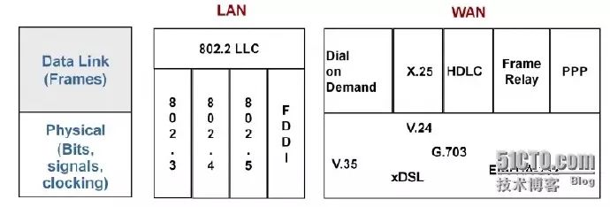
Data link layer protocols specify the encapsulation method of frames in the data link layer.
Commonly used data link layer protocols in local area networks include the IEEE802.2 LLC standard.
Commonly used data link layer protocols in wide area networks include:
-
HDLC (High-level Data Link Control)
-
PPP (Point-to-Point Protocol)
-
FR (Frame Relay)
Data Link Layer – Ethernet Address (MAC Address)
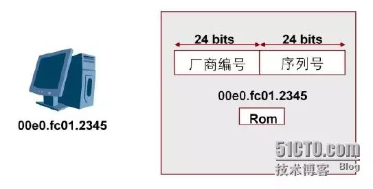
The MAC address of a network device is globally unique. A MAC address consists of 48 binary bits and is typically represented using hexadecimal digits. The first 6 hexadecimal digits are uniformly assigned to device manufacturers by IEEE, while the remaining 6 hexadecimal digits are assigned by the manufacturer itself.
Network Layer
-
Function: Forwards packets between different networks
-
Provides logical addresses; if data is transmitted across networks, logical addresses are needed for addressing.
-
Routing: Forwards data packets from one network to another.
-
Devices: Routers, Layer 3 switches
Network Layer Protocols
Commonly used network layer protocols include:
-
IP (Internet Protocol): IP is the main protocol at the network layer, serving the primary functions of the network layer: providing logical addressing, routing functionality, and encapsulation/decapsulation of messages. ICMP, ARP, and RARP protocols assist IP in its operations.
-
ICMP (Internet Control Message Protocol) is a management protocol that provides information services for IP, with ICMP messages carried within IP packets.
-
ARP (Address Resolution Protocol) achieves dynamic mapping from IP addresses to hardware addresses, i.e., obtaining the corresponding hardware address based on a known IP address.
-
RARP (Reverse Address Resolution Protocol) achieves dynamic mapping from hardware addresses to IP addresses, i.e., obtaining the corresponding IP address based on a known hardware address.
Network layer addresses uniquely identify a network device at the network layer.
A network address consists of two parts: Network ID + Host ID (the main content of the next section)
Transport Layer
Main functions:
-
Segments upper layer data;
-
Establishes end-to-end connections;
-
Transmits data from one host to another;
-
Ensures data is transmitted in order, reliably, and correctly.
Transport Layer Protocols:
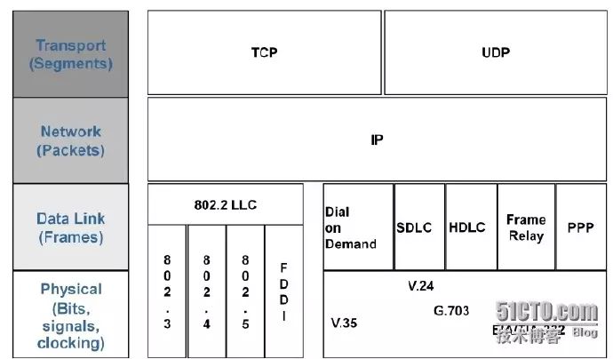
The transport layer protocols mainly include TCP (Transmission Control Protocol) and UDP (User Datagram Protocol).
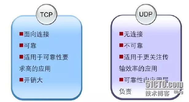
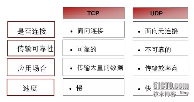
TCP provides connection-oriented, reliable byte stream services. Connection-oriented means that two applications using TCP as the transport layer protocol must establish a TCP connection before exchanging data. TCP provides reliable transmission services to upper layer applications through mechanisms like acknowledgment, checksums, and reassembly. However, establishing TCP connections and mechanisms like acknowledgment and checksumming require significant resources and can incur substantial overhead.
UDP provides simple, connectionless services. UDP does not guarantee reliability, meaning it does not ensure that messages will reach their destination. UDP is suitable for applications that prioritize transmission efficiency, such as SNMP and Radius. For instance, SNMP monitors networks and intermittently sends alerts; if a TCP connection were established for each small piece of information sent, it would undoubtedly reduce transmission efficiency. Therefore, applications like SNMP and Radius, which focus on transmission efficiency, choose UDP as their transport layer protocol. Additionally, UDP is suitable for application layer protocols that have their own reliability mechanisms.
Application Layer
-
Provides interfaces for users and processes specific applications;
-
Data encryption, decryption, compression, and decompression;
-
Defines standards for data representation.
Application Layer Protocols
There are many protocols at the application layer, and the following protocols can help you use and manage TCP/IP networks:
-
FTP (File Transfer Protocol): Used for transferring independent files, typically for interactive user sessions.
-
HTTP (Hypertext Transfer Protocol): Used for transmitting files that make up web pages on the World Wide Web.
-
TELNET: Remote terminal access. Used to transmit data with TELNET control information. It provides a standard method for interacting with terminal devices or terminal processes, supporting terminal-to-terminal connections and distributed computing communications between processes.
-
SMTP (Simple Mail Transfer Protocol) and
-
POP3 (Post Office Protocol): Used for sending and receiving emails.
-
DNS (Domain Name Server): A protocol for domain name services, providing conversion from domain names to IP addresses, allowing decentralized management of domain resources.
-
TFTP (Trivial File Transfer Protocol): Designed for general-purpose, high-throughput file transfers.
-
RIP (Routing Information Protocol): A protocol used by routers to exchange routing information over IP networks.
-
SNMP (Simple Network Management Protocol): Used to collect network management information and exchange it between network management consoles and network devices (e.g., routers, bridges, and servers).
-
Radius (Remote Authentication Dial In User Service): A protocol for authenticating, authorizing, and accounting for access users.
Encapsulation Process of TCP/IP Protocol Stack
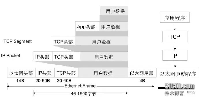
Taking the example of using TCP or UDP at the transport layer, IP at the network layer, and Ethernet at the link layer, the encapsulation process of packets in TCP/IP is illustrated in the figure above. User data is encapsulated by the application layer protocol and passed to the transport layer, where the TCP header is added, then passed to the network layer, which adds the IP header, and finally passed to the data link layer, which encapsulates it with the Ethernet frame header and trailer, sending it to the physical layer, which transmits the data as a bit stream over the physical medium.
TCP Segment
Overview of TCP Protocol:
TCP provides applications with a connection-oriented, reliable service.
Reliability of TCP:
-
Connection-oriented transmission
-
Maximum segment length
-
Transmission acknowledgment mechanism
-
Checksum for header and data
-
Flow control
TCP Header Format
TCP uses IP as the network layer protocol, and TCP segments are encapsulated within an IP packet. A TCP segment consists of a TCP Header and TCP Data.
The TCP header can be a maximum of 60 bytes long, and if no optional fields are present, the normal length is 20 bytes. The TCP header consists of several commonly used fields as identified in the figure above.
-
16-bit source port number: TCP assigns a source port number to the source application.
-
16-bit destination port number: The port number of the destination application. Each TCP segment includes the source and destination port numbers to find the originating and receiving application processes. These two values, along with the source and destination IP addresses in the IP header, uniquely identify a TCP connection.
-
32-bit sequence number: Used to identify the byte stream sent from the TCP sender to the TCP receiver.
-
32-bit acknowledgment sequence number: The acknowledgment sequence number contains the next expected sequence number for the sender. It is the last successfully received sequence number plus one.
-
4-bit header length: Indicates the number of 32-bit words in the header. Since the maximum length of the TCP header is 60 bytes.
-
16-bit window size: Indicates the number of bytes the receiving end expects to receive, with a maximum value of 65535 bytes due to this field being 16 bits.
-
16-bit checksum: The checksum covers the entire TCP segment, including the TCP header and TCP data. This value is calculated and stored by the sender and verified by the receiver.
The three-way handshake (establishing a connection) and four-way handshake (terminating a connection) of TCP
Establishing a TCP connection involves a three-way handshake process. As shown in the figure:
1. The requesting end (usually called the client) sends a SYN segment indicating that the client wishes to connect to the server port, with an initial sequence number of a.
2. The server responds with a SYN segment with a sequence number of b, while setting the acknowledgment number to the client’s sequence number plus one (a+1) as confirmation of the client’s SYN message.
3. The client sets its sequence number to the server’s sequence number plus one (b+1) as confirmation of the server’s SYN segment.
These three segments complete the establishment of the TCP connection.
Establishing a TCP connection is a three-way handshake process, while terminating a TCP connection requires a four-way handshake.
As shown in the figure:
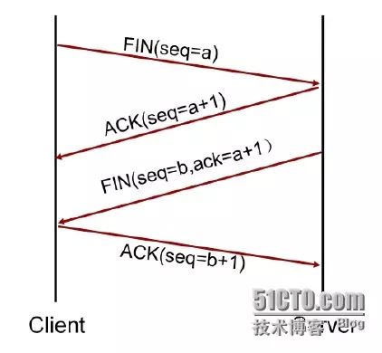
1. The requesting end (usually called the client) sends a FIN segment to terminate the connection, setting the sequence number to a.
2. The server responds with an ACK segment with the acknowledgment number set to the client’s sequence number plus one (a+1) as confirmation of the client’s FIN message.
3. The server sends a FIN termination segment to the client (setting the sequence number to b and the acknowledgment number to a+1).
4. The client returns an acknowledgment message (setting the sequence number to b+1) as a response.
These four interactions complete the closure of the connection in both directions.
TCP sliding window mechanism:
The TCP sliding window technology adjusts data transmission between two hosts by dynamically changing the window size. Each TCP/IP host supports full-duplex data transmission, so TCP has two sliding windows: one for receiving data and another for sending data. TCP uses positive acknowledgment technology, with its acknowledgment number referring to the next expected byte.
As shown in the figure, taking unidirectional data transmission as an example, the sliding window is illustrated in how it achieves flow control. The server sends four data segments, each 1024 bytes in size, to the client, with the sending end’s window size being 4096; the client responds with ACK 4097, adjusting the window size to 2048, indicating that the client (the receiving end) can only process 2048 bytes of data segments. Therefore, the sending end adjusts its sending rate to accommodate the receiving end’s capacity of 2048 bytes.
Overview of UDP Protocol
-
UDP provides applications with connectionless services. No connection needs to be established before transmitting data between the source and destination.
-
It does not need to maintain connection states, send/receive states, etc., allowing the server to simultaneously transmit the same message to multiple clients.
-
UDP is suitable for applications with high transmission efficiency requirements.
UDP Header Format
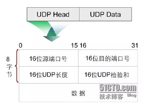
Like TCP, UDP also uses IP as its network layer protocol, and UDP datagrams are encapsulated within an IP packet. Because UDP does not provide reliable transmission like TCP, its message format is relatively simple.
The entire UDP header includes the following identifiers:
-
16-bit source port number: A source port number assigned to the source application.
-
16-bit destination port number: The port number of the destination application.
-
16-bit UDP length: Refers to the byte length of the UDP header and UDP data. The minimum value of this field is 8.
-
16-bit UDP checksum: This field provides the same function as the TCP checksum, but in the UDP protocol, this field is optional.
TCP VS UDP
IP Packet
After the transport layer receives the TCP segment, it adds the network layer IP header information. The standard IP header has a fixed length of 20 bytes (excluding the IP options field).
The main fields of the IP header include: the length of the header is the number of 32-bit words, including any options. Since this is a 4-bit field, the maximum value is 15, indicating that the header can be up to 15 * 32 bits, or 60 bytes long.
The version field indicates the version of the IP protocol, currently version 4. The next generation of the IP protocol is version 6. The 8-bit Type of Service (TOS) field includes a 3-bit priority field, 4 bits for TOS, and 1 unused bit. The 4-bit TOS represents minimum delay, maximum throughput, highest reliability, and minimum cost. The total length is the length of the entire IP datagram, including the data portion. Since this field is 16 bits long, the maximum length of the IP datagram can reach 65535 bytes. Although an IP datagram can be as long as 65535 bytes, most link layers will fragment it. Additionally, hosts are required not to receive datagrams larger than 576 bytes. UDP limits user datagram length to 512 bytes, less than 576 bytes. In fact, most current implementations (especially those supporting Network File System (NFS)) allow IP datagrams larger than 8192 bytes. The identifier field uniquely identifies each data packet sent by a host. Typically, the value increases by 1 for each sent packet. The Time to Live (TTL) field sets the number of routers a packet can pass through. Once a router processes a packet, the TTL value decreases by 1, and when this field reaches 0, the packet is discarded. The protocol field identifies the upper layer protocol to be transmitted within the packet, similar to the port number, with the protocol number distinguishing upper layer protocols. The protocol number for TCP is 6, while for UDP it is 17. The header checksum field calculates the checksum of the IP header to check the integrity of the header. The source IP address and destination IP address fields identify the source and destination devices’ IP addresses.
Ethernet Frame
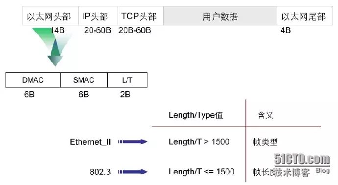
The Ethernet header consists of three fields:
DMAC: Represents the destination MAC address.
SMAC: Represents the source MAC address.
LENGTH/TYPE field: Depending on the value, it has different meanings:
When LENGTH/TYPE > 1500, it indicates the type of the data frame (e.g., upper layer protocol type). Common protocol types include:
-
0X0800 IP packet
-
0X0806 ARP request/response message
-
0X8035 RARP request/response message.
When LENGTH/TYPE < 1500, it indicates the length of the data frame.
Case Analysis
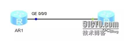
As shown in the figure above, through the example of the TELNET protocol’s packet capture instance, further deepening the understanding of packet encapsulation.
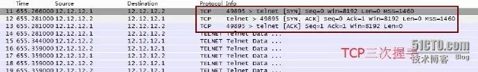
The figure above shows the TCP three-way handshake process of AR1 using the TELNET protocol to remotely log in to AR2.
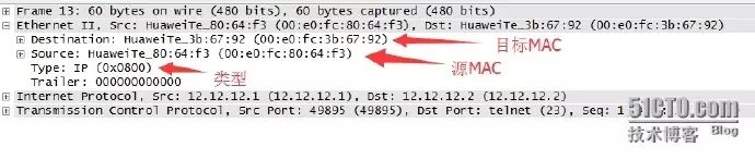
The figure above shows the encapsulation at the data link layer. It can be seen that the Ethernet II format is used for encapsulation.
DMAC: 00e0:fc3b:6792 SMAC: 00e0:fc80:64f3 type: field is 0x0800 indicating that the data field encapsulation is an IP message.
The figure above shows the encapsulation at the network layer. A network layer IP packet consists of an IP header and IP data.
The figure indicates it is an IPv4 message.
The header is 20 bytes long.
The protocol field is 0x06, indicating that the data encapsulation is a TCP message.
The source IP address of the data is 12.12.12.1, and the destination IP address is 12.12.12.2.

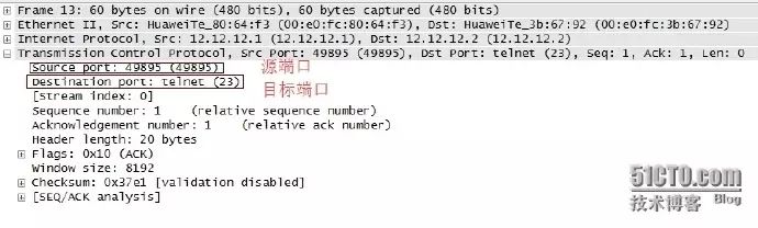
The figure above shows the encapsulation at the transport layer. As shown, the transport layer uses the TCP protocol.
The source port number is a randomly assigned port number 49895, and the destination port number is the well-known TELNET protocol port number 23.
Appendix:
Common default port numbers. The packet format at the network layer contains an important field called the protocol number. For example, if it is a TCP connection at the transport layer, the protocol number in the network layer IP packet will have a value of 6; if it is UDP, that value will be 17.
Transport Layer – Associated through interfaces (the field for ports is called port) – Application Layer.
Using netstat -an, you can view the open port numbers on the local machine.
Common proxy server ports:
-
HTTP protocol proxy server common ports: 80/8080/3128/8081/9080
-
SOCKS proxy protocol server common port: 1080
-
FTP file transfer protocol proxy server common port: 21
-
TELNET remote login protocol proxy server common port: 23
-
HTTP server’s default port is 80/tcp; the Trojan Executor opens this port.
-
HTTPS securely transferring web pages server’s default port is 443/tcp 443/udp
-
TELNET insecure text transfer default port is 23/tcp; the Trojan Tiny Telnet Server opens this port.
-
FTP default port is 21/tcp; Trojans Doly Trojan, Fore, InvisibleFTP, WebEx, WinCrash, and Blade Runner open this port.
-
TFTP Trivial File Transfer Protocol default port is 69/udp
-
SSH secure login, SCP file transfer, port redirection default port is 22/tcp
-
SMTP Simple Mail Transfer Protocol (E-mail) default port is 25/tcp; Trojans Antigen, EmailPassword Sender, Haebu Coceda, ShtrilitzStealth, WinPC, and WinSpy all open this port.
-
POP3 Post Office Protocol (E-mail) default port is 110/tcp
-
WebLogic default port is 7001
-
WebSphere application default port is 9080
-
WebSphere management tool default port is 9090
-
JBOSS default port is 8080
-
TOMCAT default port is 8080
-
WIN2003 remote login default port is 3389
-
Symantec AV/Filter for MSE, default port is 8081; Oracle database default port is 1521
-
ORACLE EMCTL default port is 1158
-
Oracle XDB XML database default port is 8080
-
Oracle XDB FTP service default port is 2100
-
MS SQL*SERVER database server default port is 1433/tcp 1433/udp
-
MS SQL*SERVER database monitor default port is 1434/tcp 1434/udp
-
QQ default port is 1080/udp
[Today’s recommended WeChat public accounts ↓

For more recommendations, see“Recommended Technical and Design Public Accounts“
Which recommends popular public accounts related to technology, design, geeks, and IT matchmaking. Technology covers: Python, Web front-end, Java, Android, iOS, PHP, C/C++, .NET, Linux, databases, operation and maintenance, big data, algorithms, IT workplace, etc. Click on “Recommended Technical and Design Public Accounts” to discover exciting content!