There are various interfaces for LCDs, with detailed classifications. The main focus is on the driving and control methods of the LCD. Currently, the connection methods for color LCDs on mobile phones generally include: MCU mode, RGB mode, SPI mode, VSYNC mode, MDDI mode, and DSI mode.
MCU mode is also referred to as MPU mode. Only TFT modules have RGB interfaces. However, the most commonly used modes are MCU mode and RGB mode, with the following differences:
1
MCU Interface: Decodes commands, generates timing signals from the timing generator, and drives COM and SEG drivers.
RGB Interface: When writing to the LCD register setting, there is no difference from the MCU interface. The difference lies only in the way images are written.
2
When using MCU mode, data can be stored in the IC’s internal GRAM before being written to the screen, allowing this mode’s LCD to be directly connected to the MEMORY bus.
In contrast, when using RGB mode, it does not have internal RAM; HSYNC, VSYNC, ENABLE, CS, RESET, and RS can be directly connected to the MEMORY’s GPIO ports, simulating waveforms using GPIO ports.
3
MPU Interface Mode: Displays data written to DDRAM, commonly used for displaying static images.
RGB Interface Mode: Displays data is not written to DDRAM, directly written to the screen, which is faster and commonly used for displaying videos or animations.
MCU Mode
It is primarily used in the field of microcontrollers, and later widely used in mid-to-low-end mobile phones, characterized by low cost.
The standard term for the MCU-LCD interface is the 8080 bus standard proposed by Intel, hence in many documents, it is referred to as I80 for MCU-LCD screens. It can further be divided into 8080 mode and 6800 mode, with the primary difference being the timing.
Data bit transmission can be 8, 9, 16, 18, or 24 bits. The connections include: CS/, RS (register select), RD/, WR/, and then the data lines.
Advantages: Simple and convenient control, no clock and synchronization signals required.
Disadvantages: Requires GRAM, making it difficult to achieve large screens (above 3.8 inches).
For MCU interface LCMs, the internal chip is called the LCD driver. Its main function is to transform the data/commands sent by the host into RGB data for each pixel, allowing it to be displayed on the screen. This process does not require point, line, or frame clocks.
The Driver ICs of MCU interface LCDs come with GRAM, and the Driver IC acts as a co-processor of the MCU, accepting Command/Data sent from the MCU and can operate relatively independently.
For MCU interface LCMs (LCD Modules), the internal chip is called the LCD driver. Its main function is to transform the data/commands sent by the host into RGB data for each pixel, allowing it to be displayed on the screen. This process does not require point, line, or frame clocks.
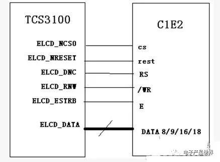
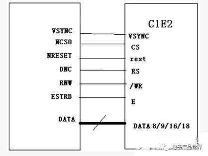
M6800 Mode
M6800 mode supports selectable bus widths of 8/9/16/18 bits (default is 8 bits). Its design concept is similar to that of I80, with the main difference being that the bus control read/write signals are combined on one pin (/WR), while an additional latch signal (E) is added. Data bit transmission can be 8, 9, 16, or 18 bits.
I8080 Mode
I80 mode connections include: CS/, RS (register select), RD/, WR/, and then the data lines.
Advantages: Simple and convenient control, no clock and synchronization signals required.
Disadvantages: Requires GRAM, making it difficult to achieve large screens (above QVGA).
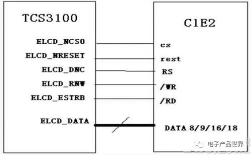
MCU interface standard name is I80, with 5 control pins: CS chip select signal; RS (set to 1 for writing data, set to 0 for writing commands); /WR (0 indicates writing data) command/data distinction signal; /RD (0 indicates reading data); RESET resets the LCD (using the fixed command series 0 1 0 to reset).
VSYNC Mode
This mode essentially adds a VSYNC signal to the MCU mode, applied for updating moving images, thus having significant differences from the previous two interfaces. It supports direct animation display functionality, providing a solution for animation display with minimal modifications to the MCU interface.
In this mode, the internal display operations are synchronized with the external VSYNC signal, allowing for animation displays at rates higher than internal operations. However, due to its different operational mode, this mode has a limitation on the rate, which is that the write rate to the internal SRAM must be greater than the read rate from the display of the internal SRAM.
RGB Mode
This mode is commonly used for larger screens, with data bit transmission varying between 6, 16, 18, and 24 bits. The connections generally include: VSYNC, HSYNC, DOTCLK, CS, RESET, and sometimes RS, with the remaining being data lines. Its advantages and disadvantages are exactly the opposite of those of the MCU mode.

Different Memory Locations
The main difference between MCU-LCD screens and RGB-LCD screens lies in the location of the video memory.
The video memory of RGB-LCD is provided by the system memory, so its size is only limited by the size of the system memory. This allows RGB-LCD to achieve larger sizes, as currently a 4.3″ is only considered entry-level, while 7″ and 10″ screens are starting to be widely used in MIDs.
In contrast, the design of MCU-LCD initially considered the small memory of microcontrollers, so the video memory is built into the LCD module. Software updates the video memory through specific display commands, which is why MCU screens often cannot be made very large. Additionally, the display update speed is slower than RGB-LCD.
Different Data Transmission Modes
There are also differences in the display data transmission modes. RGB screens only need to organize data in video memory. Once display is started, the LCD-DMA will automatically send the data from video memory to LCM via the RGB interface.
In contrast, MCU screens need to send commands to draw points to modify the RAM of the MCU (i.e., cannot directly write to the RAM of the MCU screen). Therefore, RGB display speeds are significantly faster than MCU, and for video playback, MCU-LCD is also comparatively slow.
For RGB interface LCMs, the host outputs direct RGB data for each pixel without transformation (except for GAMMA correction, etc.). For this interface, an LCD controller is required on the host side to generate RGB data and point, line, and frame synchronization signals.

Color TFT LCDs mainly have two types of interfaces: TTL interface (RGB color interface) and LVDS interface (which packages RGB color into differential signals for transmission). The TTL interface is mainly used for small TFT screens under 12.1 inches, while the LVDS interface is primarily used for large TFT screens above 8 inches.
The TTL interface has more lines and a shorter transmission distance; the LVDS interface has a longer transmission distance with fewer lines. Larger screens commonly use this mode, with control pins including VSYNC, HSYNC, VDEN, VCLK. The S3C2440 supports a maximum of 24 data pins, with data pins being VD[23-0].
The image data sent by the CPU or graphics card is TTL signals (0-5V, 0-3.3V, 0-2.5V, or 0-1.8V), and the LCD itself also receives TTL signals. Due to the poor performance of TTL signals over long distances at high speeds and their weak anti-interference capability, several transmission modes have been proposed, such as LVDS, TDMS, GVIF, P&D, DVI, and DFP.
They essentially encode the TTL signals sent by the CPU or graphics card into various signals for transmission, which are then decoded back to TTL signals upon reception by the LCD.
However, regardless of the transmission mode used, the fundamental TTL signals remain the same.
TTL/LVDS are two different signal transmission modes, where TTL is a mode where high level represents 1 and low level represents 0, while LVDS uses positive and negative corresponding waveforms to represent the current value of 1 or 0 based on the difference between the two waveforms.
Other Modes
SPI Mode
This mode is less commonly used, with 3-wire and 4-wire configurations, with connections for CS/, SLK, SDI, and SDO. While the wiring is minimal, software control is relatively complex.
MDD Mode
By reducing the number of connections, it can improve the reliability of mobile phones and reduce power consumption, which may replace SPI mode as the high-speed serial interface in mobile applications. The main connections include host_data, host_strobe, client_data, client_strobe, power, and GND.
DSI Mode
This mode is a serial bidirectional high-speed command transmission mode, with connections including D0P, D0N, D1P, D1N, CLKP, and CLKN.

Editor: Dai Qingran
Review: Chen Yan