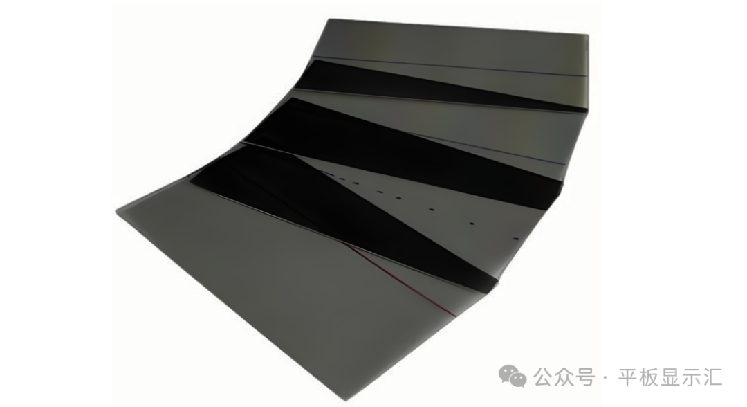
 TFT-LCD Display Module ESD Testing Diagram
In the fields of electronics and optoelectronic displays, there exists a frequently overlooked but potentially serious “invisible killer”—static electricity (ESD).
When static electricity is discharged onto a TFT-LCD display module, it can cause functional issues such as black screens, white screens, distorted screens, horizontal lines, vertical lines, flickering, and shadowing on the display.
Mild cases may result in “soft failures”, which can be recovered by restarting the display module; severe cases can damage the TFT-LCD display panel, driver IC, and components, leading to permanent loss of function and “hard failures”.
Static electricity discharges are characterized by their universality, diverse generation methods, suddenness, potentiality, and difficulty in detection. Therefore, we can only minimize the impact of static discharges on electronic devices and optoelectronic display components, but cannot eliminate them.
In previous articles, we discussed the types of coatings used in TFT-LCD display modules, conductive silver paste, and the use of polarizers with anti-static agents to release and conduct static electricity. The links to those articles are as follows:
【Technical Insights】Understanding Why TFT-LCD Panels Need Conductive Silver Paste Coating?
【Technical Insights】Understanding the Anti-Static Agents in PSA Adhesives for Polarizers and Their Matching Principles with TFT-LCD Panels
Of course, there are many more materials involved in static electricity conduction in TFT-LCD display modules beyond coatings, conductive silver paste, and polarizers.
Based on the standards summarized during project development, I will share the static control standards and specifications for key materials in TFT-LCD display modules in a “hands-on” manner with friends in the display community.
These materials mainly include primary materials and packaging materials, as detailed below:
 Details of ESD Control Materials for TFT-LCD Display Modules
Having organized the materials involved in ESD control for TFT-LCD display modules, we will now elaborate on their respective control specifications and standards.
Of course, the control standards discussed in this article are relatively general and should be tailored to the actual situation of different customers and projects.
Since the article will involve key parameters affecting static discharge, such as resistance values, sheet resistance, and friction/peel voltage, it is necessary to briefly explain the mechanisms of these core parameters on material static discharge before discussing the static control specifications and standards.
① The greater the material’s resistance and sheet resistance, the poorer its conductivity, resulting in a slower charge flow rate, which means the static discharge process will be very slow, and the impact of static electricity on the product will be greater.
According to Ohm’s law, current I = voltage U / resistance R, when resistance R is large, under the same static voltage U, the current I through the material will be very small, indicating that the flow rate of static charge is very low, and the static discharge process will be very slow.
② The greater the friction/peel voltage of the material, the more static energy it accumulates, making static discharge more difficult, and the impact of static electricity on the product will be greater.
According to the basic principles of electrostatics, static energy W = 1/2 CV2 (where C represents capacitance and V represents voltage), when the voltage V increases, the static energy W will increase quadratically.
Due to the large number of materials involved, this topic will be divided into two articles for detailed elaboration. Today’s article will mainly focus on materials such as cover protective films, cover plates, polarizers, driver ICs, TFT-LCD display panels, and backlight modules.
The protective film attached to the front of the glass cover plate has strict requirements for the sheet resistance and peel voltage values of the adhesive surface. The larger these two values are within a certain range, the more likely it is to cause peeling shadows and white spots during the peeling process when attached to the surface of the TFT-LCD display module.
Generally, the sheet resistance of the adhesive surface of the cover protective film is controlled according to 10^5~10^9Ω/□, and the peel voltage is controlled at ≤500V (peel speed >20cm/s, distance from the cover plate surface to the testing instrument is 5~20cm).
Some customers may require the peel voltage of both the cover surface and the adhesive surface of the protective film to meet ≤500V, which places relatively high demands on the protective film and needs to be confirmed through practical testing based on the material of the cover plate used.
Because the same protective film, when paired with different materials for the cover plate, will yield different peel voltage values in testing.
 Cover Protective Film on the Front of the Glass
2. Cover Plate
The material of the glass cover plate itself does not affect the static discharge capacity, but it is listed here mainly due to the ink printed on the cover plate.
The size of the ink resistance value can affect the touch sensitivity, especially in previous high-end gold and rose gold colored mobile phone cover plates with touch buttons, as the relatively small ink resistance (adding metal powder or carbon black in the ink reduces ink resistance) affects the touch effect.
Theoretically, the ink resistance value should be larger, ideally approaching an insulating state.
Generally, the ink resistance is controlled to ≥10^9Ω (1000MΩ) (testing voltage level 1000V, testing probe spacing 10mm).
 Cover Plate
3. Polarizer
Previous articles have discussed anti-static polarizers, with the core point being that the content and type of anti-static agents added to the PSA glue of the polarizer will affect the sheet resistance of the PSA glue, thereby influencing the static discharge capacity of the TFT-LCD display module.
Generally, the polarizer that has requirements for the sheet resistance of the PSA adhesive surface is the upper polarizer. According to the size of the sheet resistance of the polarizer’s PSA adhesive surface, polarizers can be divided into: low-resistance polarizers, standard-resistance polarizers, and high-resistance polarizers. Their respective sheet resistance ranges are as follows:
Low-resistance polarizer range: 10^8~10^9 Ω/□
Standard-resistance polarizer range: 10^10~10^12 Ω/□
High-resistance polarizer range: ≥10^12 Ω/□
Of course, the sheet resistance of the polarizer’s PSA adhesive surface is not necessarily better if it is lower; it needs to be chosen in conjunction with the touch type and coating conditions of the paired TFT-LCD display panel.
Polarizer
4. Driver IC
The driver IC discussed here mainly refers to the anti-static voltage values of the IC unit under different discharge modes.
Of course, software aspects will also include settings related to enhancing the anti-static capacity of the IC, such as adding ESD Check functionality, modifying Mipi timing, enhancing the stability of Mipi signal transmission, and improving the IC’s anti-interference ability in CMD mode, etc.
Generally, under human discharge mode (HBM), the anti-static voltage requirement for the IC unit is ≥2.5~3.0KV; under machine discharge mode (MM), the anti-static voltage requirement for the IC unit is ≥200~300V; under component charging mode (CDM), the anti-static voltage requirement for the IC unit is ≥800V.
5. TFT-LCD Display Panel
In the TFT-LCD display panel, there are many design solutions to improve the anti-static capacity of the panel, such as designing GND traces (GND Ring) around the LCD AA area, ESD protection circuits for GOA, ESD protection circuits for the touch layer, the position of the silver paste AG Pad on the LCD, and the coating on the LCD surface.
 TFT-LCD ESD Protection Design Diagram
This section will focus on the control standards for the sheet resistance after coating on the LCD surface. The main types of coatings for the LCD surface are: ATO film (tin oxide antimony) and ITO film (indium tin oxide).
ATO film, also known as high-resistance film, is usually used in In-cell projects, primarily to prevent touch signal interference, while also facilitating static conduction. The control requirement for the sheet resistance after coating is: 1X10 ^8~9.9X10 ^9Ω/□, specifically determined based on customer needs and vendor capabilities.
ITO film, also known as conductive film, is usually used in IPS display mode external projects, mainly serving the purpose of static conduction. The control requirement for the sheet resistance after coating is: ≤1000Ω/□, with stricter requirements being ≤200~300Ω/□.
6. Backlight Module
The materials that affect the anti-static capacity of the TFT-LCD display module or the Waving of the film material in the backlight module mainly include: LED lights, backlight iron frames, and optical films. We will elaborate on the control requirements of these materials related to static electricity.
 Cross Section of Backlight Module
① LED Lights: As the core component providing the light source, the anti-static capacity of the LED lights directly affects whether the LED lights can function normally during static discharges, determining whether the TFT-LCD display module can display correctly. Damage to the LED lights falls under functional defects.
Generally, a single LED light’s anti-static voltage requirement in human discharge mode (HBM) is ≥2.0~3.0KV, with a stricter requirement of ≥4.0KV. If there are stricter requirements, consider adding TVS tubes to the LED light strips to further enhance the anti-static capacity of the LEDs.
② Backlight Iron Frame: The material used for the backlight iron frame in small-sized backlight modules is generally SUS304 or SUS201, and the size of its resistance value also has a certain impact on static discharge.
Generally, the surface resistance value of the backlight iron frame is required to be ≤3Ω. If lower resistance values are needed, consider using nickel-plated iron frames, which can meet ≤1Ω surface resistance.
③ Optical Film Materials: The optical film materials in the backlight module mainly include brightness enhancement films, diffusion films, and reflective films.
The materials of brightness enhancement films, diffusion films, and reflective films do not significantly affect the anti-static capacity; generally, the surface sheet resistance requirement for these materials is ≥10^13Ω/□. If a single adhesive frame backlight solution is used, the type of reflective film can affect the size of the anti-static capacity, which is related to the type of reflective film used.
Another point to note is that the voltage value of the optical film materials must be strictly controlled before assembly into the backlight, specifically the voltage value on the material at the discharge platform.
Generally, at the discharge platform, the voltage value of the surface of the optical film materials is required to be ≤500~750V; the smaller this voltage value, the lower the risk of the reliability of the latter film materials experiencing Waving.
Well, that’s it for today’s sharing. This is acontent-rich public account, adhering to the principle of “saying everything without holding back”, and I hope it helps you.
I am an exceptional individual with over 10 years of experience in the display industry, having progressed from a technical novice to a technical director and product technology expert, skilled at addressing various technical issues in display products. I hope to help everyone avoid the pitfalls I’ve encountered. Follow my public account, add me as a friend, and let me help you navigate the complexities of flat panel display technology. Remember to mark it as a star to see articles as soon as they are published.
Follow the public account or add me as a WeChat friend, and reply “small tool” in the background to receive free image editing and drawing format conversion tools~
Recommended Previous Articles:
【Technical Insights】Understanding the Box Process of TFT-LCD Panels (6500-word detailed explanation)
【Technical Insights】Understanding Why TFT-LCD Panels Need Conductive Silver Paste Coating?
【Technical Insights】Understanding the Most Widely Used Backing Materials for TFT-LCD Panels – a-Si
【Technical Insights】Understanding the Narrow Bezel Implementation Solutions and Challenges for TFT-LCD Panels
【Technical Insights】Understanding the TFT-LCD Array Process (6000-word detailed explanation)
